2003 DODGE RAM air bleeding
[x] Cancel search: air bleedingPage 232 of 2895
STANDARD PROCEDURE
STANDARD PROCEDURE - MANUAL BLEEDING
Use Mopar brake fluid, or an equivalent quality
fluid meeting SAE J1703-F and DOT 3 standards
only. Use fresh, clean fluid from a sealed container at
all times.
(1) Remove reservoir filler caps and fill reservoir.
(2) If calipers, or wheel cylinders were overhauled,
open all caliper and wheel cylinder bleed screws.
Then close each bleed screw as fluid starts to drip
from it. Top off master cylinder reservoir once more
before proceeding.
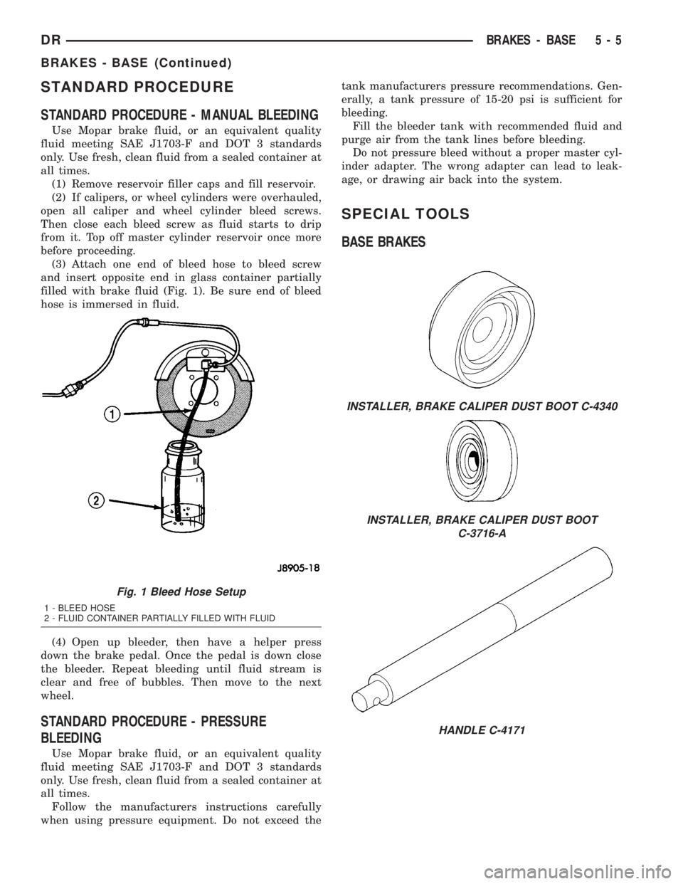
(3) Attach one end of bleed hose to bleed screw
and insert opposite end in glass container partially
filled with brake fluid (Fig. 1). Be sure end of bleed
hose is immersed in fluid.
(4) Open up bleeder, then have a helper press
down the brake pedal. Once the pedal is down close
the bleeder. Repeat bleeding until fluid stream is
clear and free of bubbles. Then move to the next
wheel.
STANDARD PROCEDURE - PRESSURE
BLEEDING
Use Mopar brake fluid, or an equivalent quality
fluid meeting SAE J1703-F and DOT 3 standards
only. Use fresh, clean fluid from a sealed container at
all times.
Follow the manufacturers instructions carefully
when using pressure equipment. Do not exceed thetank manufacturers pressure recommendations. Gen-
erally, a tank pressure of 15-20 psi is sufficient for
bleeding.
Fill the bleeder tank with recommended fluid and
purge air from the tank lines before bleeding.
Do not pressure bleed without a proper master cyl-
inder adapter. The wrong adapter can lead to leak-
age, or drawing air back into the system.
SPECIAL TOOLS
BASE BRAKES
Fig. 1 Bleed Hose Setup
1 - BLEED HOSE
2 - FLUID CONTAINER PARTIALLY FILLED WITH FLUID
INSTALLER, BRAKE CALIPER DUST BOOT C-4340
INSTALLER, BRAKE CALIPER DUST BOOT
C-3716-A
HANDLE C-4171
DRBRAKES - BASE 5 - 5
BRAKES - BASE (Continued)
Page 247 of 2895

cuit separation in the event of a front or rear brake
malfunction. The reservoir compartments will retain
enough fluid to operate the functioning hydraulic cir-
cuit.
Care must be exercised when removing/installing
the master cylinder connecting lines. The threads in
the cylinder fluid ports can be damaged if care is not
exercised. Start all brake line fittings by hand to
avoid cross threading.
The cylinder reservoir can be replaced when neces-
sary. However, the aluminum body section of the
master cylinder is not a repairable component.
NOTE: If diagnosis indicates that an internal mal-
function has occurred, the aluminum body section
must be replaced as an assembly.
OPERATION
The master cylinder bore contains a primary and
secondary piston. The primary piston supplies
hydraulic pressure to the front brakes. The secondary
piston supplies hydraulic pressure to the rear brakes.
DIAGNOSIS AND TESTING - MASTER
CYLINDER/POWER BOOSTER
(1) Start engine and check booster vacuum hose
connections. A hissing noise indicates vacuum leak.
Correct any vacuum leak before proceeding.
(2) Stop engine and shift transmission into Neu-
tral.
(3) Pump brake pedal until all vacuum reserve in
booster is depleted.
(4) Press and hold brake pedal under light foot
pressure. The pedal should hold firm, if the pedal
falls away master cylinder is faulty (internal leak-
age).
(5) Start engine and note pedal action. It should
fall away slightly under light foot pressure then hold
firm. If no pedal action is discernible, power booster,
vacuum supply, or vacuum check valve is faulty. Pro-
ceed to the POWER BOOSTER VACUUM TEST.
(6) If the POWER BOOSTER VACUUM TEST
passes, rebuild booster vacuum reserve as follows:
Release brake pedal. Increase engine speed to 1500
rpm, close the throttle and immediately turn off igni-
tion to stop engine.
(7) Wait a minimum of 90 seconds and try brake
action again. Booster should provide two or more vac-
uum assisted pedal applications. If vacuum assist is
not provided, booster is faulty.
POWER BOOSTER VACUUM TEST
(1) Connect vacuum gauge to booster check valve
with short length of hose and T-fitting (Fig. 36).(2) Start and run engine at curb idle speed for one
minute.
(3) Observe the vacuum supply. If vacuum supply
is not adequate, repair vacuum supply.
(4) Clamp hose shut between vacuum source and
check valve.
(5) Stop engine and observe vacuum gauge.
(6) If vacuum drops more than one inch HG (33
millibars) within 15 seconds, booster diaphragm or
check valve is faulty.
POWER BOOSTER CHECK VALVE TEST
(1) Disconnect vacuum hose from check valve.
(2) Remove check valve and valve seal from
booster.
(3) Use a hand operated vacuum pump for test.
(4) Apply 15-20 inches vacuum at large end of
check valve (Fig. 37).
(5) Vacuum should hold steady. If gauge on pump
indicates vacuum loss, check valve is faulty and
should be replaced.
STANDARD PROCEDURE - MASTER CYLINDER
BLEEDING
A new master cylinder should be bled before instal-
lation on the vehicle. Required bleeding tools include
bleed tubes and a wood dowel to stroke the pistons.
Bleed tubes can be fabricated from brake line.
Fig. 36 Typical Booster Vacuum Test Connections
1 - TEE FITTING
2 - SHORT CONNECTING HOSE
3 - CHECK VALVE
4 - CHECK VALVE HOSE
5 - CLAMP TOOL
6 - INTAKE MANIFOLD
7 - VACUUM GAUGE
5 - 20 BRAKES - BASEDR
MASTER CYLINDER (Continued)
Page 248 of 2895
(1) Mount master cylinder in vise.
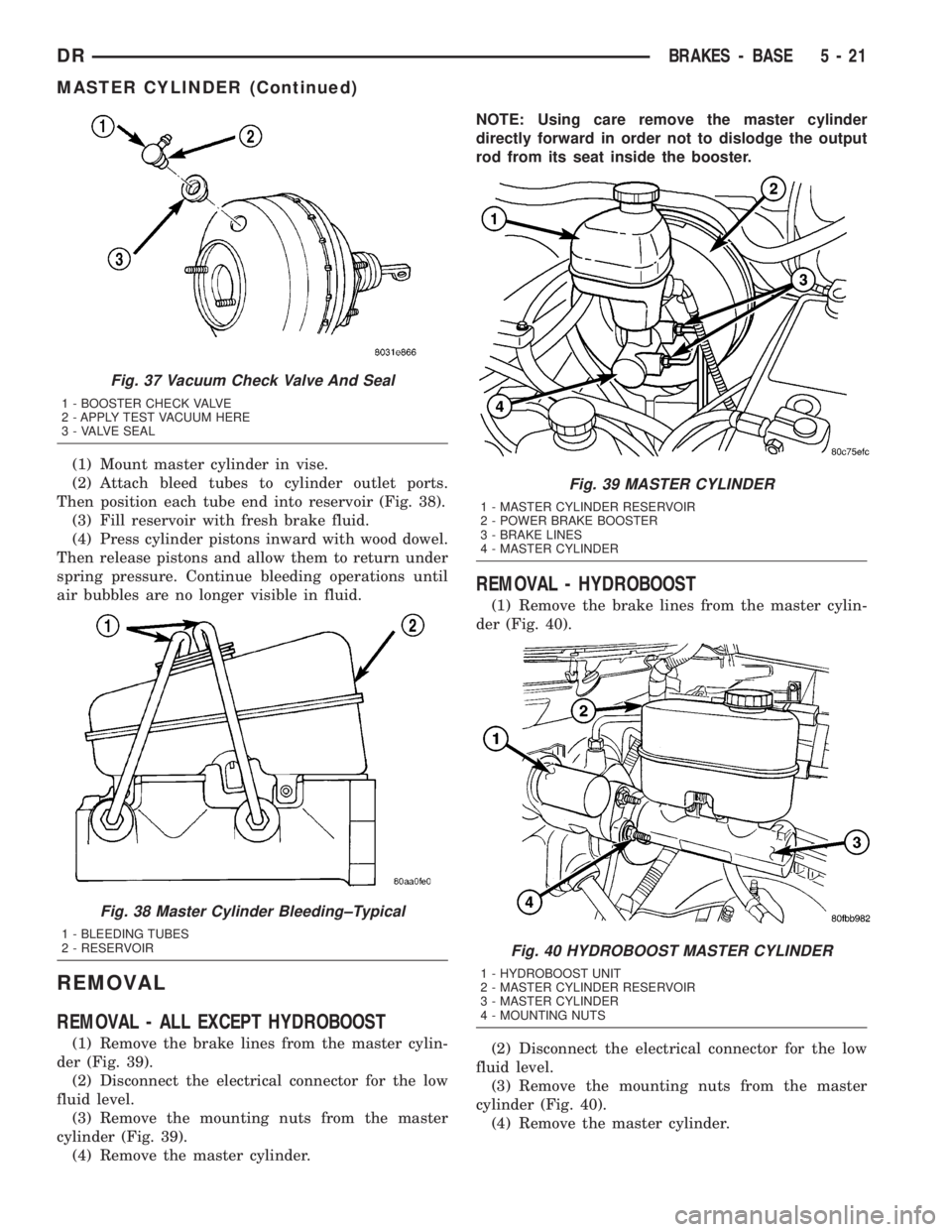
(2) Attach bleed tubes to cylinder outlet ports.
Then position each tube end into reservoir (Fig. 38).
(3) Fill reservoir with fresh brake fluid.
(4) Press cylinder pistons inward with wood dowel.
Then release pistons and allow them to return under
spring pressure. Continue bleeding operations until
air bubbles are no longer visible in fluid.
REMOVAL
REMOVAL - ALL EXCEPT HYDROBOOST
(1) Remove the brake lines from the master cylin-
der (Fig. 39).
(2) Disconnect the electrical connector for the low
fluid level.
(3) Remove the mounting nuts from the master
cylinder (Fig. 39).
(4) Remove the master cylinder.NOTE: Using care remove the master cylinder
directly forward in order not to dislodge the output
rod from its seat inside the booster.
REMOVAL - HYDROBOOST
(1) Remove the brake lines from the master cylin-
der (Fig. 40).
(2) Disconnect the electrical connector for the low
fluid level.
(3) Remove the mounting nuts from the master
cylinder (Fig. 40).
(4) Remove the master cylinder.
Fig. 37 Vacuum Check Valve And Seal
1 - BOOSTER CHECK VALVE
2 - APPLY TEST VACUUM HERE
3 - VALVE SEAL
Fig. 38 Master Cylinder Bleeding±Typical
1 - BLEEDING TUBES
2 - RESERVOIR
Fig. 39 MASTER CYLINDER
1 - MASTER CYLINDER RESERVOIR
2 - POWER BRAKE BOOSTER
3 - BRAKE LINES
4 - MASTER CYLINDER
Fig. 40 HYDROBOOST MASTER CYLINDER
1 - HYDROBOOST UNIT
2 - MASTER CYLINDER RESERVOIR
3 - MASTER CYLINDER
4 - MOUNTING NUTS
DRBRAKES - BASE 5 - 21
MASTER CYLINDER (Continued)
Page 254 of 2895
CONDITION POSSIBLE CAUSES CORRECTION
Brakes Self Apply 1. Dump valve faulty. 1. Replace booster.
2. Contamination in hydraulic
system.2. Flush hydraulic system and replace
booster.
3. Restriction in booster return hose. 3. Replace hose.
Booster Chatter, Pedal
Vibration1. Slipping pump belt. 1. Replace power steering belt.
2. Low pump fluid level. 2. Fill pump and check for leaks.
Grabbing Brakes 1. Low pump flow. 1. Test and repair/replace pump.
2. Faulty spool valve action. 2. Replace booster.
STANDARD PROCEDURE - BLEEDING
The hydraulic booster is generally self-bleeding,
this procedure will normally bleed the air from the
booster. Normal driving and operation of the unit will
remove any remaining trapped air.
(1) Fill power steering pump reservoir.
(2) Disconnect fuel shutdown relay and crank the
engine for several seconds, Refer to Fuel System for
relay location and WARNING.
(3) Check fluid level and add if necessary.
(4) Connect fuel shutdown relay and start the
engine.
(5) Turn the steering wheel slowly from lock to
lock twice.
(6) Stop the engine and discharge the accumulator
by depressing the brake pedal 5 times.
(7) Start the engine and turn the steering wheel
slowly from lock to lock twice.
(8) Turn off the engine and check fluid level and
add if necessary.
NOTE: If fluid foaming occurs, wait for foam to dis-
sipate and repeat steps 7 and 8.
REMOVAL
NOTE: If the booster is being replaced because the
power steering fluid is contaminated, flush the
power steering system before replacing the booster.
(1) With engine off depress the brake pedal 5
times to discharge the accumulator.
(2) Remove brake lines from master cylinder.
(3) Remove mounting nuts from the master cylin-
der.
(4) Remove the bracket from the hydraulic booster
lines and master cylinder mounting studs.
(5) Remove the master cylinder.
(6) Remove the return hose and the two pressure
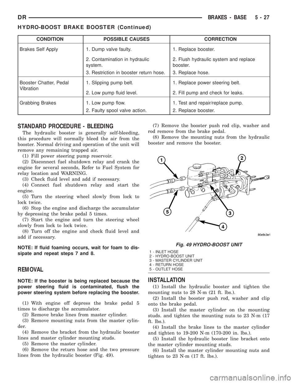
lines from the hydraulic booster (Fig. 49).(7) Remove the booster push rod clip, washer and
rod remove from the brake pedal.
(8) Remove the mounting nuts from the hydraulic
booster and remove the booster.INSTALLATION
(1) Install the hydraulic booster and tighten the
mounting nuts to 28 N´m (21 ft. lbs.).
(2) Install the booster push rod, washer and clip
onto the brake pedal.
(3) Install the master cylinder on the mounting
studs. and tighten the mounting nuts to 23 N´m (17
ft. lbs.).
(4) Install the brake lines to the master cylinder
and tighten to 19-200 N´m (170-200 in. lbs.).
(5) Install the hydraulic booster line bracket onto
the master cylinder mounting studs.
(6) Install the master cylinder mounting nuts and
tighten to 23 N´m (17 ft. lbs.).
Fig. 49 HYDRO-BOOST UNIT
1 - INLET HOSE
2 - HYDRO-BOOST UNIT
3 - MASTER CYLINDER UNIT
4 - RETURN HOSE
5 - OUTLET HOSE
DRBRAKES - BASE 5 - 27
HYDRO-BOOST BRAKE BOOSTER (Continued)
Page 267 of 2895

The purpose of the antilock system is to prevent
wheel lockup. Preventing lockup helps maintain vehi-
cle braking action and steering control.
The antilock CAB activates the system whenever
sensor signals indicate periods of wheel slip.
The antilock system prevents lockup during a
wheel slip condition by modulating fluid apply pres-
sure to the wheel brake units.
Brake fluid apply pressure is modulated according
to wheel speed, degree of slip and rate of decelera-
tion. Sensors at each front wheel convert wheel speed
into electrical signals. These signals are transmitted
to the CAB for processing and determination of
wheel slip and deceleration rate.
The ABS system has three fluid pressure control
channels. The front brakes are controlled separately
and the rear brakes in tandem. A speed sensor input
signal indicating a wheel slip condition activates the
CAB antilock program.
There are Two solenoid valves (Isolation and Dump
valve) which are used in each antilock control chan-
nel. The valves are all located within the HCU valve
body and work in pairs to either increase, hold, or
decrease apply pressure as needed in the individual
control channels.
During an ABS stop the ISO valve is energized
which acts to prevent further pressure build-up tothe calipers. Then the Dump valve dumps off pres-
sure until the wheel unlocks. This will continue until
the wheels quit slipping altogether.
STANDARD PROCEDURE - ABS BRAKE
BLEEDING
ABS system bleeding requires conventional bleed-
ing methods plus use of the DRB scan tool. The pro-
cedure involves performing a base brake bleeding,
followed by use of the scan tool to cycle and bleed the
HCU pump and solenoids. A second base brake bleed-
ing procedure is then required to remove any air
remaining in the system.
(1) Perform base brake bleeding,(Refer to 5 -
BRAKES - STANDARD PROCEDURE) OR (Refer to
5 - BRAKES - STANDARD PROCEDURE).
(2) Connect scan tool to the Data Link Connector.
(3) Select ANTILOCK BRAKES, followed by MIS-
CELLANEOUS, then ABS BRAKES. Follow the
instructions displayed. When scan tool displays TEST
COMPLETE, disconnect scan tool and proceed.
(4) Perform base brake bleeding a second time,(Re-
fer to 5 - BRAKES - STANDARD PROCEDURE) OR
(Refer to 5 - BRAKES - STANDARD PROCEDURE).
(5) Top off master cylinder fluid level and verify
proper brake operation before moving vehicle.
SPECIFICATIONS
TORQUE CHART
TORQUE SPECIFICATIONS
DESCRIPTION N´m Ft. Lbs. In. Lbs.
ABS Assembly
Mounting Bolts15 11 Ð
ABS Assembly
CAB Screws3.5 Ð 31
ABS Assembly
Brake Line Fittings19 Ð 170
Wheel Speed Sensors
Front Sensor Bolt21 Ð 190
Wheel Speed Sensors
Bracket To Knuckle6.7 Ð 60
Wheel Speed Sensors
Rear Sensor Stud22.5 Ð 200
Controller
Mounting Screws6Ð53
RWAL Module
Mounting Bolts15 11 Ð
5 - 40 BRAKES - ABSDR
BRAKES - ABS (Continued)
Page 2047 of 2895
OPERATION
The application of the piston is accomplished by
applying pressure between the two lands of the piston.
The pressure acts against the larger lower land to push
the piston downward, allowing the piston rod to extend
though its guide against the apply lever. Release of the
servo at the 2-3 upshift is accomplished by a combina-
tion of spring and line pressure, acting on the bottom of
the larger land of the piston. The small piston is used to
cushion the application of the band by bleeding oil
through a small orifice in the larger piston. The release
timing of the kickdown servo is very important to obtain
a smooth but firm shift. The release has to be very
quick, just as the front clutch application is taking
place. Otherwise, engine runaway or a shift hesitation
will occur. To accomplish this, the band retains its hold-
ing capacity until the front clutch is applied, giving a
small amount of overlap between them.
DISASSEMBLY
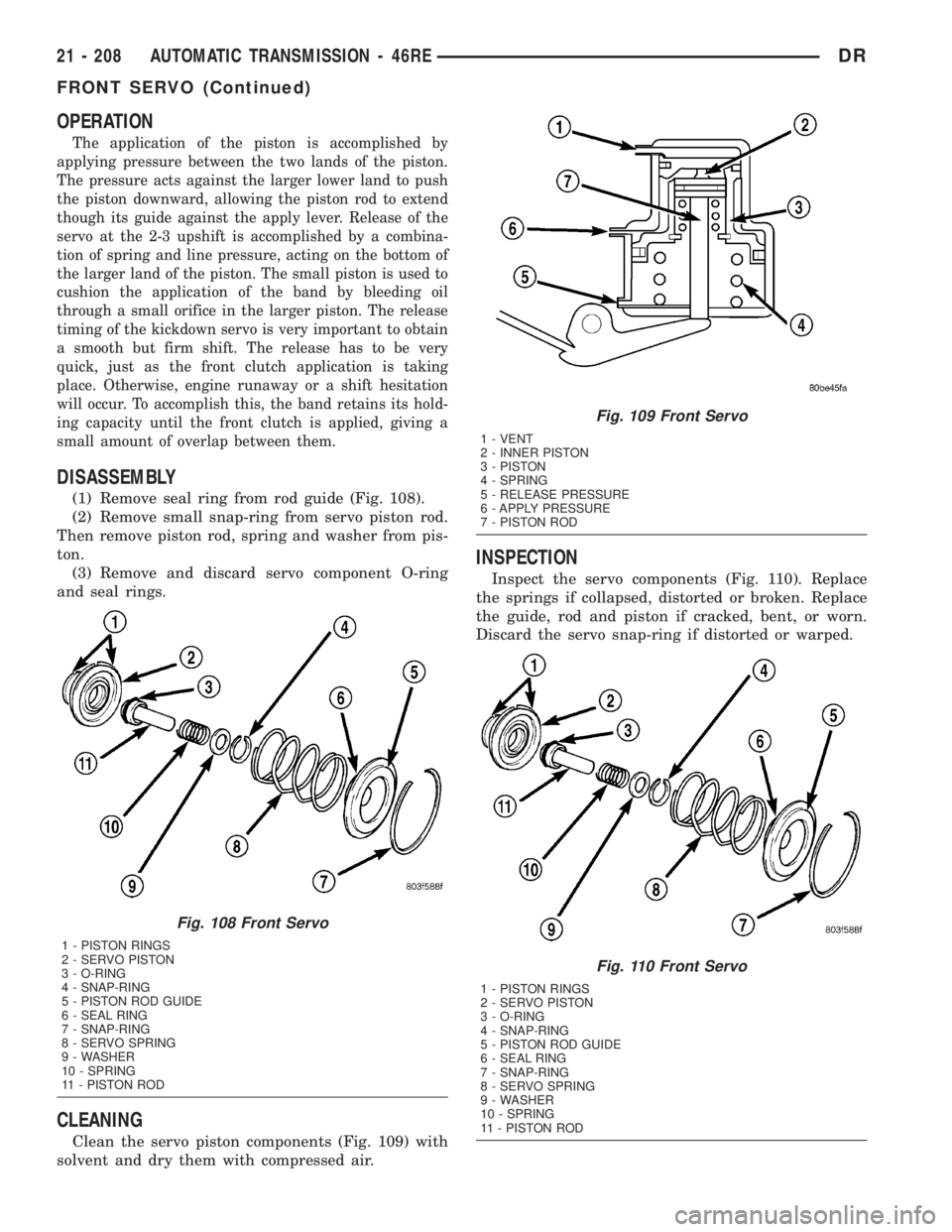
(1) Remove seal ring from rod guide (Fig. 108).
(2) Remove small snap-ring from servo piston rod.
Then remove piston rod, spring and washer from pis-
ton.
(3) Remove and discard servo component O-ring
and seal rings.
CLEANING
Clean the servo piston components (Fig. 109) with
solvent and dry them with compressed air.
INSPECTION
Inspect the servo components (Fig. 110). Replace
the springs if collapsed, distorted or broken. Replace
the guide, rod and piston if cracked, bent, or worn.
Discard the servo snap-ring if distorted or warped.
Fig. 108 Front Servo
1 - PISTON RINGS
2 - SERVO PISTON
3 - O-RING
4 - SNAP-RING
5 - PISTON ROD GUIDE
6 - SEAL RING
7 - SNAP-RING
8 - SERVO SPRING
9 - WASHER
10 - SPRING
11 - PISTON ROD
Fig. 109 Front Servo
1 - VENT
2 - INNER PISTON
3 - PISTON
4 - SPRING
5 - RELEASE PRESSURE
6 - APPLY PRESSURE
7 - PISTON ROD
Fig. 110 Front Servo
1 - PISTON RINGS
2 - SERVO PISTON
3 - O-RING
4 - SNAP-RING
5 - PISTON ROD GUIDE
6 - SEAL RING
7 - SNAP-RING
8 - SERVO SPRING
9 - WASHER
10 - SPRING
11 - PISTON ROD
21 - 208 AUTOMATIC TRANSMISSION - 46REDR
FRONT SERVO (Continued)
Page 2856 of 2895
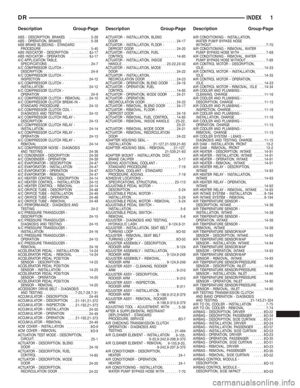
ABS - DESCRIPTION, BRAKES...........5-39
ABS - OPERATION, BRAKES.............5-39
ABS BRAKE BLEEDING - STANDARD
PROCEDURE.........................5-40
ABS INDICATOR - DESCRIPTION.........8J-17
ABS INDICATOR - OPERATION..........8J-17
A/C APPLICATION TABLE,
SPECIFICATIONS......................24-7
A/C COMPRESSOR CLUTCH -
DESCRIPTION........................24-9
A/C COMPRESSOR CLUTCH -
INSPECTION........................24-12
A/C COMPRESSOR CLUTCH -
INSTALLATION.......................24-12
A/C COMPRESSOR CLUTCH -
OPERATION..........................24-9
A/C COMPRESSOR CLUTCH - REMOVAL . . 24-10
A/C COMPRESSOR CLUTCH BREAK-IN -
STANDARD PROCEDURE...............24-10
A/C COMPRESSOR CLUTCH COIL -
DIAGNOSIS AND TESTING.............24-10
A/C COMPRESSOR CLUTCH RELAY -
DESCRIPTION.......................24-13
A/C COMPRESSOR CLUTCH RELAY -
INSTALLATION.......................24-14
A/C COMPRESSOR CLUTCH RELAY -
OPERATION.........................24-13
A/C COMPRESSOR CLUTCH RELAY -
REMOVAL..........................24-14
A/C COMPRESSOR NOISE - DIAGNOSIS
AND TESTING.......................24-36
A/C CONDENSER - DESCRIPTION.........24-39
A/C CONDENSER - OPERATION..........24-39
A/C EVAPORATOR - DESCRIPTION.......24-47
A/C EVAPORATOR - INSTALLATION......24-47
A/C EVAPORATOR - OPERATION.........24-47
A/C EVAPORATOR - REMOVAL..........24-47
A/C HEATER CONTROL - DESCRIPTION . . . 24-14
A/C HEATER CONTROL - INSTALLATION . . . 24-15
A/C HEATER CONTROL - REMOVAL......24-14
A/C ORIFICE TUBE - DESCRIPTION.......24-48
A/C ORIFICE TUBE - INSTALLATION......24-49
A/C ORIFICE TUBE - OPERATION........24-48
A/C ORIFICE TUBE - REMOVAL..........24-49
A/C PERFORMANCE - DIAGNOSIS AND
TESTING............................24-2
A/C PRESSURE TRANSDUCER -
DESCRIPTION.......................24-15
A/C PRESSURE TRANSDUCER -
DIAGNOSIS AND TESTING.............24-15
A/C PRESSURE TRANSDUCER -
INSTALLATION.......................24-16
A/C PRESSURE TRANSDUCER -
OPERATION.........................24-15
A/C PRESSURE TRANSDUCER -
REMOVAL..........................24-16
ACCELERATOR PEDAL - INSTALLATION . . . 14-24
ACCELERATOR PEDAL - REMOVAL.......14-24
ACCELERATOR PEDAL POSITION
SENSOR - DESCRIPTION...............14-25
ACCELERATOR PEDAL POSITION
SENSOR - INSTALLATION..............14-25
ACCELERATOR PEDAL POSITION
SENSOR - OPERATION................14-25
ACCELERATOR PEDAL POSITION
SENSOR - REMOVAL..................14-25
ACCESSORY DRIVE BELT - DIAGNOSIS
AND TESTING................7-25,7-28,7-31
ACCUMULATOR - DESCRIPTION.........24-49
ACCUMULATOR - DESCRIPTION
. . 21-191,21-372
ACCUMULATOR - INSPECTION
. . . 21-192,21-373
ACCUMULATOR - INSTALLATION
........24-50
ACCUMULATOR - OPERATION
..........24-49
ACCUMULATOR - OPERATION
....21-192,21-373
ACCUMULATOR - REMOVAL
............24-49
ACM COVER - INSTALLATION
............8O-9
ACM COVER - REMOVAL
...............8O-9
ACTUATION TEST MODE - DESCRIPTION,
CIRCUIT
.............................25-1
ACTUATOR - DESCRIPTION, BLEND
DOOR
.............................24-16
ACTUATOR - DESCRIPTION, FUEL
CONTROL
..........................14-85
ACTUATOR - DESCRIPTION, MODE
DOOR
.............................24-20
ACTUATOR - DESCRIPTION,
RECIRCULATION DOOR
................24-22ACTUATOR - INSTALLATION, BLEND
DOOR.............................24-17
ACTUATOR - INSTALLATION, FLOOR -
DEFROST DOOR.....................24-20
ACTUATOR - INSTALLATION, FUEL
CONTROL..........................14-85
ACTUATOR - INSTALLATION, INSIDE
HANDLE.......................23-22,23-32
ACTUATOR - INSTALLATION, MODE
DOOR.............................24-22
ACTUATOR - INSTALLATION,
RECIRCULATION DOOR................24-23
ACTUATOR - OPERATION, BLEND DOOR . . 24-16
ACTUATOR - OPERATION, FUEL
CONTROL..........................14-85
ACTUATOR - OPERATION, MODE DOOR . . . 24-21
ACTUATOR - OPERATION,
RECIRCULATION DOOR................24-22
ACTUATOR - REMOVAL, BLEND DOOR....24-17
ACTUATOR - REMOVAL, FLOOR -
DEFROST DOOR.....................24-19
ACTUATOR - REMOVAL, FUEL CONTROL . . 14-85
ACTUATOR - REMOVAL, INSIDE HANDLE . 23-22,
23-31
ACTUATOR - REMOVAL, MODE DOOR....24-21
ACTUATOR - REMOVAL, RECIRCULATION
DOOR.............................24-22
ADAPTER HOUSING SEAL -
INSTALLATION...........21-127,21-539,21-83
ADAPTER HOUSING SEAL - REMOVAL . . 21-127,
21-539,21-83
ADAPTER MOUNT - INSTALLATION, DISC
BRAKE CALIPER......................5-17
ADDING ADDITIONAL COOLANT -
STANDARD PROCEDURE................7-19
ADDITIONAL COOLANT - STANDARD
PROCEDURE, ADDING..................7-19
ADHESIVE LOCATIONS -
SPECIFICATIONS, STRUCTURAL........23-113
ADJUSTABLE PEDAL MOTOR -
DESCRIPTION........................5-24
ADJUSTABLE PEDAL MOTOR -
INSTALLATION........................5-24
ADJUSTABLE PEDAL MOTOR - REMOVAL . . 5-24
ADJUSTABLE PEDAL SWITCH -
INSTALLATION.........................5-6
ADJUSTABLE PEDAL SWITCH -
REMOVAL............................5-6
ADJUSTER - DIAGNOSIS AND TESTING,
HYDRAULIC LASH................9-124,9-31
ADJUSTER - INSTALLATION, SEAT BELT
TURNING LOOP.....................8O-50
ADJUSTER - REMOVAL, SEAT BELT
TURNING LOOP.....................8O-50
ADJUSTER ASSEMBLY - DESCRIPTION,
ROCKER ARM.......................9-124
ADJUSTER ASSEMBLY - INSTALLATION,
ROCKER ARM..................9-124,9-249
ADJUSTER ASSEMBLY - REMOVAL,
ROCKER ARM..................9-124,9-249
ADJUSTER ASSY - CLEANING, ROCKER
ARM
..............................9-310
ADJUSTER ASSY - DESCRIPTION,
ROCKER ARM
.......................9-310
ADJUSTER ASSY - INSPECTION,
ROCKER ARM
.......................9-311
ADJUSTER ASSY - INSTALLATION,
ROCKER ARM
.............9-198,9-312,9-379
ADJUSTER ASSY - REMOVAL, ROCKER
ARM
....................9-198,9-310,9-379
ADJUSTING TOOL - ADJUSTMENT, WITH
. . . 5-36
AFTER A SUPPLEMENTAL RESTRAINT
DEPLOYMENT - STANDARD
PROCEDURE, SERVICE
.................8O-7
AIR CHECKING TRANSMISSION CLUTCH
OPERATION - DIAGNOSIS AND
TESTING
..........................21-494
AIR CLEANER ELEMENT - INSTALLATION
. 9-105,
9-20,9-242,9-298,9-370
AIR CLEANER ELEMENT - REMOVAL
. 9-105,9-20,
9-242,9-297,9-370
AIR CONDITIONER - DESCRIPTION,
HEATER
.............................24-1
AIR CONDITIONER - OPERATION,
HEATER
.............................24-1
AIR CONDITIONING - INSTALLATION,
WATER PUMP BYPASS HOSE WITH
.......7-70AIR CONDITIONING - INSTALLATION,
WATER PUMP BYPASS HOSE
WITHOUT............................7-70
AIR CONDITIONING - REMOVAL, WATER
PUMP BYPASS HOSE WITH.............7-68
AIR CONDITIONING - REMOVAL, WATER
PUMP BYPASS HOSE WITHOUT..........7-69
AIR CONTROL MOTOR - DESCRIPTION,
IDLE...............................14-33
AIR CONTROL MOTOR - INSTALLATION,
IDLE...............................14-35
AIR CONTROL MOTOR - OPERATION,
IDLE...............................14-33
AIR CONTROL MOTOR - REMOVAL, IDLE . . 14-34
AIR COOLER AND PLUMBING -
CLEANING, CHARGE..................11-16
AIR COOLER AND PLUMBING -
DESCRIPTION, CHARGE...............11-15
AIR COOLER AND PLUMBING -
INSPECTION, CHARGE.................11-16
AIR COOLER AND PLUMBING -
INSTALLATION, CHARGE...............11-16
AIR COOLER AND PLUMBING -
OPERATION, CHARGE.................11-15
AIR COOLER AND PLUMBING -
REMOVAL, CHARGE..................11-15
AIR COOLER SYSTEM - LEAKS -
DIAGNOSIS AND TESTING, CHARGE......11-15
AIR DAM - INSTALLATION, FRONT........13-2
AIR DAM - REMOVAL, FRONT...........13-2
AIR HEATER - DESCRIPTION, INTAKE.....14-91
AIR HEATER - INSTALLATION, INTAKE....14-91
AIR HEATER - OPERATION, INTAKE......14-91
AIR HEATER - REMOVAL, INTAKE........14-91
AIR HEATER RELAY - DESCRIPTION,
INTAKE ............................14-92
AIR HEATER RELAY - INSTALLATION,
INTAKE ............................14-93
AIR HEATER RELAY - OPERATION,
INTAKE ............................14-92
AIR HEATER RELAY - REMOVAL, INTAKE . . 14-93
AIR INTAKE SYSTEM - INSTALLATION....9-194
AIR INTAKE SYSTEM - REMOVAL........9-194
AIR TEMPERATURE SENSOR -
DESCRIPTION, INTAKE................14-36
AIR TEMPERATURE SENSOR -
INSTALLATION, INTAKE................14-38
AIR TEMPERATURE SENSOR -
OPERATION, INTAKE..................14-36
AIR TEMPERATURE SENSOR -
REMOVAL, INTAKE...................14-36
AIR TEMPERATURE SENSOR/MAP
SENSOR - DESCRIPTION, INTAKE........14-93
AIR TEMPERATURE SENSOR/MAP
SENSOR - INSTALLATION, INTAKE.......14-94
AIR TEMPERATURE SENSOR/MAP
SENSOR - OPERATION, INTAKE.........14-93
AIR TEMPERATURE SENSOR/MAP
SENSOR - REMOVAL, INTAKE...........14-93
AIR TEMPERATURE SENSOR/PRESSURE
SENSOR - DESCRIPTION, INLET.........14-90
AIR TEMPERATURE SENSOR/PRESSURE
SENSOR - INSTALLATION, INLET........14-90
AIR TEMPERATURE SENSOR/PRESSURE
SENSOR - OPERATION, INLET..........14-90
AIR TEMPERATURE SENSOR/PRESSURE
SENSOR - REMOVAL, INLET............14-90
AIR TESTING TRANSMISSION CLUTCH
AND BAND OPERATION - DIAGNOSIS
AND TESTING................21-143,21-324
AIR TO OIL COOLER - INSTALLATION.....7-75
AIR TO OIL COOLER - REMOVAL.........7-74
AIRBAG - DESCRIPTION, DRIVER........8O-22
AIRBAG - DESCRIPTION, PASSENGER....8O-34
AIRBAG - DESCRIPTION, SIDE CURTAIN . . 8O-51
AIRBAG - INSTALLATION, DRIVER.......8O-24
AIRBAG - INSTALLATION, PASSENGER . . . 8O-37
AIRBAG - INSTALLATION, SIDE CURTAIN . . 8O-53
AIRBAG - OPERATION, DRIVER.........8O-23
AIRBAG - OPERATION, PASSENGER......8O-35
AIRBAG - OPERATION, SIDE CURTAIN....8O-51
AIRBAG - REMOVAL, DRIVER
...........8O-23
AIRBAG - REMOVAL, PASSENGER
.......8O-35
AIRBAG - REMOVAL, SIDE CURTAIN
.....8O-52
AIRBAG CONTROL MODULE -
DESCRIPTION
.......................8O-10
AIRBAG CONTROL MODULE -
DESCRIPTION, SIDE IMPACT
...........8O-53
DRINDEX 1
Description Group-Page Description Group-Page Description Group-Page
Page 2859 of 2895
BIN - INSTALLATION, STORAGE.........23-62
BIN - INSTALLATION, UNDER SEAT
STORAGE...........................23-81
BIN - REMOVAL, STORAGE.............23-62
BIN - REMOVAL, UNDER SEAT STORAGE . . 23-81
BIN COVERING - INSTALLATION, UNDER
SEAT STORAGE......................23-81
BIN COVERING - REMOVAL, UNDER
SEAT STORAGE......................23-81
BIN LATCH - INSTALLATION, UNDER
SEAT STORAGE......................23-81
BIN LATCH - REMOVAL, UNDER SEAT
STORAGE...........................23-81
BLADE - DESCRIPTION, WIPER.........8R-19
BLADE - INSTALLATION, WIPER.........8R-20
BLADE - OPERATION, WIPER...........8R-19
BLADE - REMOVAL, WIPER............8R-19
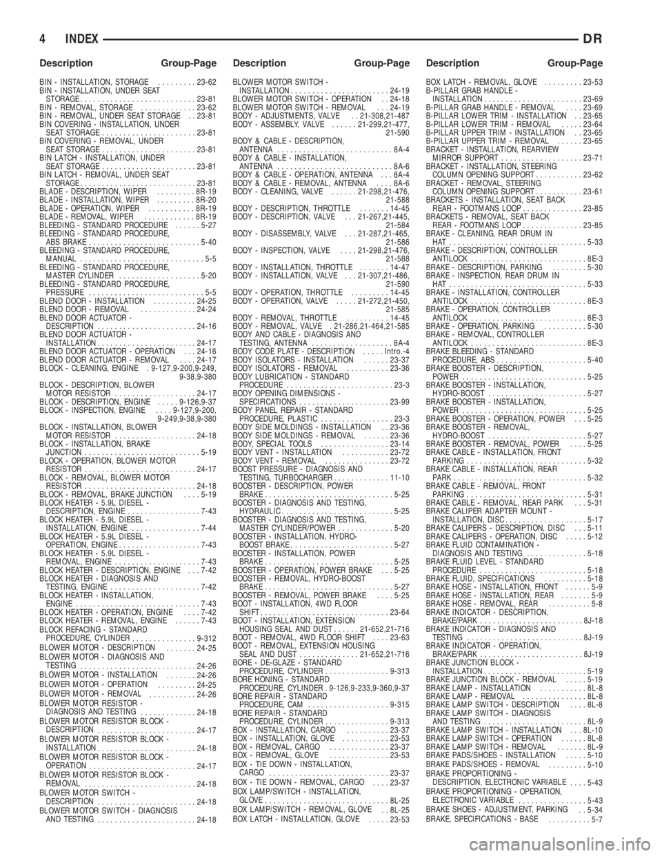
BLEEDING - STANDARD PROCEDURE......5-27
BLEEDING - STANDARD PROCEDURE,
ABS BRAKE..........................5-40
BLEEDING - STANDARD PROCEDURE,
MANUAL.............................5-5
BLEEDING - STANDARD PROCEDURE,
MASTER CYLINDER...................5-20
BLEEDING - STANDARD PROCEDURE,
PRESSURE...........................5-5
BLEND DOOR - INSTALLATION..........24-25
BLEND DOOR - REMOVAL.............24-24
BLEND DOOR ACTUATOR -
DESCRIPTION.......................24-16
BLEND DOOR ACTUATOR -
INSTALLATION.......................24-17
BLEND DOOR ACTUATOR - OPERATION . . . 24-16
BLEND DOOR ACTUATOR - REMOVAL....24-17
BLOCK - CLEANING, ENGINE . 9-127,9-200,9-249,
9-38,9-380
BLOCK - DESCRIPTION, BLOWER
MOTOR RESISTOR...................24-17
BLOCK - DESCRIPTION, ENGINE.....9-126,9-37
BLOCK - INSPECTION, ENGINE....9-127,9-200,
9-249,9-38,9-380
BLOCK - INSTALLATION, BLOWER
MOTOR RESISTOR...................24-18
BLOCK - INSTALLATION, BRAKE
JUNCTION...........................5-19
BLOCK - OPERATION, BLOWER MOTOR
RESISTOR..........................24-17
BLOCK - REMOVAL, BLOWER MOTOR
RESISTOR..........................24-18
BLOCK - REMOVAL, BRAKE JUNCTION....5-19
BLOCK HEATER - 5.9L DIESEL -
DESCRIPTION, ENGINE.................7-43
BLOCK HEATER - 5.9L DIESEL -
INSTALLATION, ENGINE................7-44
BLOCK HEATER - 5.9L DIESEL -
OPERATION, ENGINE...................7-43
BLOCK HEATER - 5.9L DIESEL -
REMOVAL, ENGINE....................7-43
BLOCK HEATER - DESCRIPTION, ENGINE . . . 7-42
BLOCK HEATER - DIAGNOSIS AND
TESTING, ENGINE.....................7-42
BLOCK HEATER - INSTALLATION,
ENGINE.............................7-43
BLOCK HEATER - OPERATION, ENGINE....7-42
BLOCK HEATER - REMOVAL, ENGINE......7-43
BLOCK REFACING - STANDARD
PROCEDURE, CYLINDER
...............9-312
BLOWER MOTOR - DESCRIPTION
.......24-25
BLOWER MOTOR - DIAGNOSIS AND
TESTING
...........................24-26
BLOWER MOTOR - INSTALLATION
.......24-26
BLOWER MOTOR - OPERATION
.........24-25
BLOWER MOTOR - REMOVAL
...........24-26
BLOWER MOTOR RESISTOR -
DIAGNOSIS AND TESTING
.............24-18
BLOWER MOTOR RESISTOR BLOCK -
DESCRIPTION
.......................24-17
BLOWER MOTOR RESISTOR BLOCK -
INSTALLATION
.......................24-18
BLOWER MOTOR RESISTOR BLOCK -
OPERATION
.........................24-17
BLOWER MOTOR RESISTOR BLOCK -
REMOVAL
..........................24-18
BLOWER MOTOR SWITCH -
DESCRIPTION
.......................24-18
BLOWER MOTOR SWITCH - DIAGNOSIS
AND TESTING
.......................24-18BLOWER MOTOR SWITCH -
INSTALLATION.......................24-19
BLOWER MOTOR SWITCH - OPERATION . . 24-18
BLOWER MOTOR SWITCH - REMOVAL . . . 24-19
BODY - ADJUSTMENTS, VALVE . . 21-308,21-487
BODY - ASSEMBLY, VALVE......21-299,21-477,
21-590
BODY & CABLE - DESCRIPTION,
ANTENNA...........................8A-4
BODY & CABLE - INSTALLATION,
ANTENNA...........................8A-6
BODY & CABLE - OPERATION, ANTENNA . . . 8A-4
BODY & CABLE - REMOVAL, ANTENNA....8A-6
BODY - CLEANING, VALVE......21-298,21-476,
21-588
BODY - DESCRIPTION, THROTTLE.......14-45
BODY - DESCRIPTION, VALVE . . . 21-267,21-445,
21-584
BODY - DISASSEMBLY, VALVE . . . 21-287,21-465,
21-586
BODY - INSPECTION, VALVE....21-298,21-476,
21-588
BODY - INSTALLATION, THROTTLE.......14-47
BODY - INSTALLATION, VALVE . . . 21-307,21-486,
21-590
BODY - OPERATION, THROTTLE.........14-45
BODY - OPERATION, VALVE.....21-272,21-450,
21-585
BODY - REMOVAL, THROTTLE..........14-45
BODY - REMOVAL, VALVE . 21-286,21-464,21-585
BODY AND CABLE - DIAGNOSIS AND
TESTING, ANTENNA...................8A-4
BODY CODE PLATE - DESCRIPTION.....Intro.-4
BODY ISOLATORS - INSTALLATION......23-37
BODY ISOLATORS - REMOVAL..........23-36
BODY LUBRICATION - STANDARD
PROCEDURE.........................23-3
BODY OPENING DIMENSIONS -
SPECIFICATIONS.....................23-99
BODY PANEL REPAIR - STANDARD
PROCEDURE, PLASTIC.................23-3
BODY SIDE MOLDINGS - INSTALLATION . . 23-36
BODY SIDE MOLDINGS - REMOVAL......23-36
BODY, SPECIAL TOOLS................23-14
BODY VENT - INSTALLATION...........23-72
BODY VENT - REMOVAL...............23-72
BOOST PRESSURE - DIAGNOSIS AND
TESTING, TURBOCHARGER.............11-10
BOOSTER - DESCRIPTION, POWER
BRAKE..............................5-25
BOOSTER - DIAGNOSIS AND TESTING,
HYDRAULIC..........................5-25
BOOSTER - DIAGNOSIS AND TESTING,
MASTER CYLINDER/POWER.............5-20
BOOSTER - INSTALLATION, HYDRO-
BOOST BRAKE........................5-27
BOOSTER - INSTALLATION, POWER
BRAKE..............................5-25
BOOSTER - OPERATION, POWER BRAKE . . . 5-25
BOOSTER - REMOVAL, HYDRO-BOOST
BRAKE..............................5-27
BOOSTER - REMOVAL, POWER BRAKE....5-25
BOOT - INSTALLATION, 4WD FLOOR
SHIFT..............................23-64
BOOT - INSTALLATION, EXTENSION
HOUSING SEAL AND DUST......21-652,21-716
BOOT - REMOVAL, 4WD FLOOR SHIFT....23-63
BOOT - REMOVAL, EXTENSION HOUSING
SEAL AND DUST..............21-652,21-716
BORE - DE-GLAZE - STANDARD
PROCEDURE, CYLINDER...............9-313
BORE HONING - STANDARD
PROCEDURE, CYLINDER . 9-126,9-233,9-360,9-37
BORE REPAIR - STANDARD
PROCEDURE, CAM...................9-315
BORE REPAIR - STANDARD
PROCEDURE, CYLINDER...............9-313
BOX - INSTALLATION, CARGO..........23-37
BOX - INSTALLATION, GLOVE...........23-53
BOX - REMOVAL, CARGO..............23-37
BOX - REMOVAL, GLOVE..............23-53
BOX - TIE DOWN - INSTALLATION,
CARGO
............................23-37
BOX - TIE DOWN - REMOVAL, CARGO
....23-37
BOX LAMP/SWITCH - INSTALLATION,
GLOVE
.............................8L-25
BOX LAMP/SWITCH - REMOVAL, GLOVE
. . 8L-25
BOX LATCH - INSTALLATION, GLOVE
.....23-53BOX LATCH - REMOVAL, GLOVE.........23-53
B-PILLAR GRAB HANDLE -
INSTALLATION.......................23-69
B-PILLAR GRAB HANDLE - REMOVAL....23-69
B-PILLAR LOWER TRIM - INSTALLATION . . 23-65
B-PILLAR LOWER TRIM - REMOVAL.....23-64
B-PILLAR UPPER TRIM - INSTALLATION . . 23-65
B-PILLAR UPPER TRIM - REMOVAL......23-65
BRACKET - INSTALLATION, REARVIEW
MIRROR SUPPORT...................23-71
BRACKET - INSTALLATION, STEERING
COLUMN OPENING SUPPORT...........23-62
BRACKET - REMOVAL, STEERING
COLUMN OPENING SUPPORT...........23-61
BRACKETS - INSTALLATION, SEAT BACK
REAR - FOOTMANS LOOP..............23-85
BRACKETS - REMOVAL, SEAT BACK
REAR - FOOTMANS LOOP..............23-85
BRAKE - CLEANING, REAR DRUM IN
HAT ................................5-33
BRAKE - DESCRIPTION, CONTROLLER
ANTILOCK...........................8E-3
BRAKE - DESCRIPTION, PARKING........5-30
BRAKE - INSPECTION, REAR DRUM IN
HAT ................................5-33
BRAKE - INSTALLATION, CONTROLLER
ANTILOCK...........................8E-3
BRAKE - OPERATION, CONTROLLER
ANTILOCK...........................8E-3
BRAKE - OPERATION, PARKING..........5-30
BRAKE - REMOVAL, CONTROLLER
ANTILOCK...........................8E-3
BRAKE BLEEDING - STANDARD
PROCEDURE, ABS.....................5-40
BRAKE BOOSTER - DESCRIPTION,
POWER.............................5-25
BRAKE BOOSTER - INSTALLATION,
HYDRO-BOOST.......................5-27
BRAKE BOOSTER - INSTALLATION,
POWER.............................5-25
BRAKE BOOSTER - OPERATION, POWER . . . 5-25
BRAKE BOOSTER - REMOVAL,
HYDRO-BOOST.......................5-27
BRAKE BOOSTER - REMOVAL, POWER....5-25
BRAKE CABLE - INSTALLATION, FRONT
PARKING............................5-32
BRAKE CABLE - INSTALLATION, REAR
PARK...............................5-32
BRAKE CABLE - REMOVAL, FRONT
PARKING............................5-31
BRAKE CABLE - REMOVAL, REAR PARK . . . 5-31
BRAKE CALIPER ADAPTER MOUNT -
INSTALLATION, DISC...................5-17
BRAKE CALIPERS - DESCRIPTION, DISC . . . 5-11
BRAKE CALIPERS - OPERATION, DISC.....5-12
BRAKE FLUID CONTAMINATION -
DIAGNOSIS AND TESTING..............5-18
BRAKE FLUID LEVEL - STANDARD
PROCEDURE.........................5-18
BRAKE FLUID, SPECIFICATIONS..........5-18
BRAKE HOSE - INSTALLATION, FRONT......5-9
BRAKE HOSE - INSTALLATION, REAR.......5-9
BRAKE HOSE - REMOVAL, REAR..........5-8
BRAKE INDICATOR - DESCRIPTION,
BRAKE/PARK........................8J-18
BRAKE INDICATOR - DIAGNOSIS AND
TESTING...........................8J-19
BRAKE INDICATOR - OPERATION,
BRAKE/PARK........................8J-19
BRAKE JUNCTION BLOCK -
INSTALLATION........................5-19
BRAKE JUNCTION BLOCK - REMOVAL.....5-19
BRAKE LAMP - INSTALLATION...........8L-8
BRAKE LAMP - REMOVAL...............8L-8
BRAKE LAMP SWITCH - DESCRIPTION....8L-8
BRAKE LAMP SWITCH - DIAGNOSIS
AND TESTING........................8L-9
BRAKE LAMP SWITCH - INSTALLATION . . . 8L-10
BRAKE LAMP SWITCH - OPERATION......8L-8
BRAKE LAMP SWITCH - REMOVAL.......8L-9
BRAKE PADS/SHOES - INSTALLATION.....5-10
BRAKE PADS/SHOES - REMOVAL
.........5-10
BRAKE PROPORTIONING -
DESCRIPTION, ELECTRONIC VARIABLE
....5-43
BRAKE PROPORTIONING - OPERATION,
ELECTRONIC VARIABLE
................5-43
BRAKE SHOES - ADJUSTMENT, PARKING
. . 5-34
BRAKE, SPECIFICATIONS - BASE
..........5-7
4 INDEXDR
Description Group-Page Description Group-Page Description Group-Page