2003 DODGE RAM sport mode
[x] Cancel search: sport modePage 1245 of 2895

IOD FUSE
DESCRIPTION
All vehicles are equipped with an Ignition-Off
Draw (IOD) fuse that is disconnected within the Inte-
grated Power Module when the vehicle is shipped
from the factory. Dealer personnel are to reconnect
the IOD fuse in the Integrated Power Module as part
of the preparation procedures performed just prior to
new vehicle delivery.
A laser printed fuse layout map is integral to the
Integrated Power Module cover to ensure proper fuse
identification. The IOD fuse is a 20 ampere mini
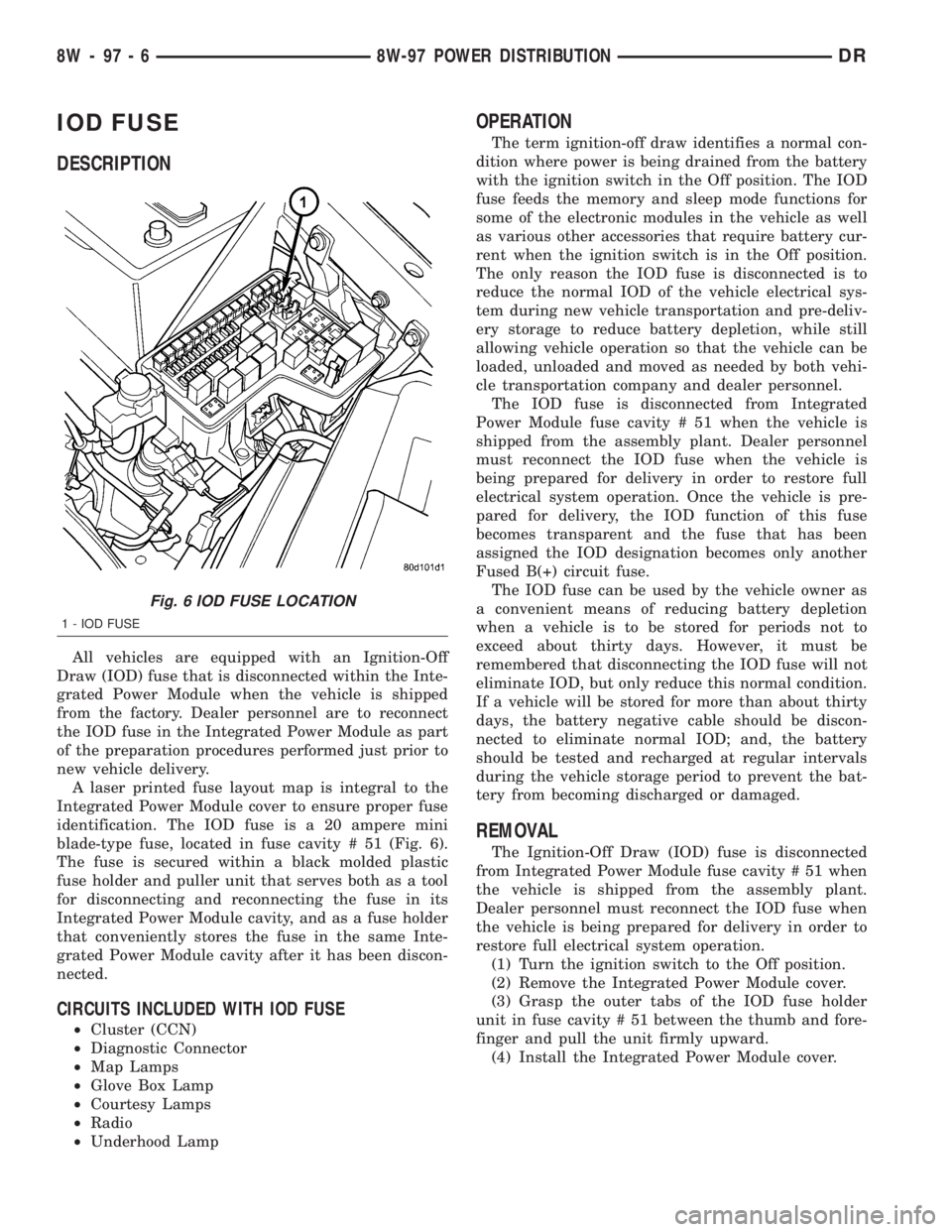
blade-type fuse, located in fuse cavity # 51 (Fig. 6).
The fuse is secured within a black molded plastic
fuse holder and puller unit that serves both as a tool
for disconnecting and reconnecting the fuse in its
Integrated Power Module cavity, and as a fuse holder
that conveniently stores the fuse in the same Inte-
grated Power Module cavity after it has been discon-
nected.
CIRCUITS INCLUDED WITH IOD FUSE
²Cluster (CCN)
²Diagnostic Connector
²Map Lamps
²Glove Box Lamp
²Courtesy Lamps
²Radio
²Underhood Lamp
OPERATION
The term ignition-off draw identifies a normal con-
dition where power is being drained from the battery
with the ignition switch in the Off position. The IOD
fuse feeds the memory and sleep mode functions for
some of the electronic modules in the vehicle as well
as various other accessories that require battery cur-
rent when the ignition switch is in the Off position.
The only reason the IOD fuse is disconnected is to
reduce the normal IOD of the vehicle electrical sys-
tem during new vehicle transportation and pre-deliv-
ery storage to reduce battery depletion, while still
allowing vehicle operation so that the vehicle can be
loaded, unloaded and moved as needed by both vehi-
cle transportation company and dealer personnel.
The IOD fuse is disconnected from Integrated
Power Module fuse cavity # 51 when the vehicle is
shipped from the assembly plant. Dealer personnel
must reconnect the IOD fuse when the vehicle is
being prepared for delivery in order to restore full
electrical system operation. Once the vehicle is pre-
pared for delivery, the IOD function of this fuse
becomes transparent and the fuse that has been
assigned the IOD designation becomes only another
Fused B(+) circuit fuse.
The IOD fuse can be used by the vehicle owner as
a convenient means of reducing battery depletion
when a vehicle is to be stored for periods not to
exceed about thirty days. However, it must be
remembered that disconnecting the IOD fuse will not
eliminate IOD, but only reduce this normal condition.
If a vehicle will be stored for more than about thirty
days, the battery negative cable should be discon-
nected to eliminate normal IOD; and, the battery
should be tested and recharged at regular intervals
during the vehicle storage period to prevent the bat-
tery from becoming discharged or damaged.
REMOVAL
The Ignition-Off Draw (IOD) fuse is disconnected
from Integrated Power Module fuse cavity # 51 when
the vehicle is shipped from the assembly plant.
Dealer personnel must reconnect the IOD fuse when
the vehicle is being prepared for delivery in order to
restore full electrical system operation.
(1) Turn the ignition switch to the Off position.
(2) Remove the Integrated Power Module cover.
(3) Grasp the outer tabs of the IOD fuse holder
unit in fuse cavity # 51 between the thumb and fore-
finger and pull the unit firmly upward.
(4) Install the Integrated Power Module cover.
Fig. 6 IOD FUSE LOCATION
1 - IOD FUSE
8W - 97 - 6 8W-97 POWER DISTRIBUTIONDR
Page 1673 of 2895

FRONT AIR DAM
REMOVAL
(1) Using a trim stick C-4755 or equivalent,
remove the fog lamp trim bezels. (Fig. 1)
(2) Remove the air dam screws through the fog
lamp opening (1 per side).
(3) Remove the two outboard screws.
(4) Remove the three middle screws and remove
the air dam.
INSTALLATION
(1) Position the air dam onto the bumper and seat
the carrot type fasteners fully.
(2) Starting at the center screw install the three
middle screws.
(3) Install the screws through the fog lamp open-
ing.
(4) Install the two outboard screws.
(5) Position the fog lamp trim bezels into the
bumper and seat fully.
FRONT BUMPER
REMOVAL
(1) Using a grease pencil or equivalent, mark the
position of the bumper on the frame rail tip to aid
installation.
(2) Disconnect the fog lamp electrical connector at
the left frame rail.
(3) Support the bumper with a suitable lifting
device.
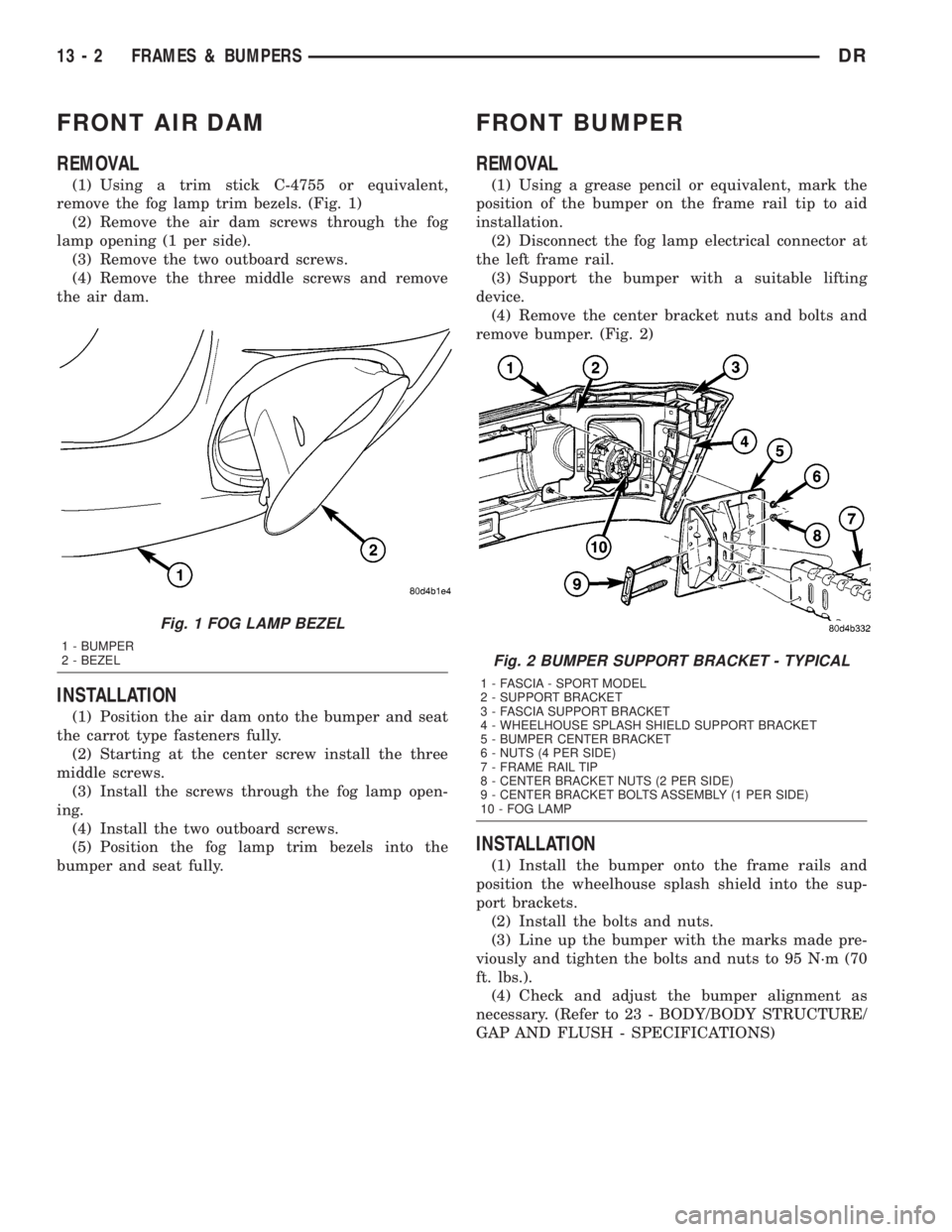
(4) Remove the center bracket nuts and bolts and
remove bumper. (Fig. 2)
INSTALLATION
(1) Install the bumper onto the frame rails and
position the wheelhouse splash shield into the sup-
port brackets.
(2) Install the bolts and nuts.
(3) Line up the bumper with the marks made pre-
viously and tighten the bolts and nuts to 95 N´m (70
ft. lbs.).
(4) Check and adjust the bumper alignment as
necessary. (Refer to 23 - BODY/BODY STRUCTURE/
GAP AND FLUSH - SPECIFICATIONS)
Fig. 1 FOG LAMP BEZEL
1 - BUMPER
2 - BEZEL
Fig. 2 BUMPER SUPPORT BRACKET - TYPICAL
1 - FASCIA - SPORT MODEL
2 - SUPPORT BRACKET
3 - FASCIA SUPPORT BRACKET
4 - WHEELHOUSE SPLASH SHIELD SUPPORT BRACKET
5 - BUMPER CENTER BRACKET
6 - NUTS (4 PER SIDE)
7 - FRAME RAIL TIP
8 - CENTER BRACKET NUTS (2 PER SIDE)
9 - CENTER BRACKET BOLTS ASSEMBLY (1 PER SIDE)
10 - FOG LAMP
13 - 2 FRAMES & BUMPERSDR
Page 1674 of 2895

FRONT FASCIA
REMOVAL
ST/SLT/SLT+ - FASCIA REMOVAL
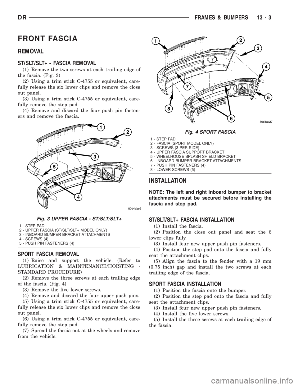
(1) Remove the two screws at each trailing edge of
the fascia. (Fig. 3)
(2) Using a trim stick C-4755 or equivalent, care-
fully release the six lower clips and remove the close
out panel.
(3) Using a trim stick C-4755 or equivalent, care-
fully remove the step pad.
(4) Remove and discard the four push pin fasten-
ers and remove the fascia.
SPORT FASCIA REMOVAL
(1) Raise and support the vehicle. (Refer to
LUBRICATION & MAINTENANCE/HOISTING -
STANDARD PROCEDURE)
(2) Remove the three screws at each trailing edge
of the fascia. (Fig. 4)
(3) Remove the five lower screws.
(4) Remove and discard the four upper push pins.
(5) Using a trim stick C-4755 or equivalent, care-
fully release the six lower clips and remove the close
out panel.
(6) Using a trim stick C-4755 or equivalent, care-
fully remove the step pad.
(7) Spread the fascia out at the wheels and remove
from the vehicle.
INSTALLATION
NOTE: The left and right inboard bumper to bracket
attachments must be secured before installing the
fascia and step pad.
ST/SLT/SLT+ FASCIA INSTALLATION
(1) Install the fascia.
(2) Position the close out panel and seat the 6
lower clips fully.
(3) Install four new upper push pin fasteners.
(4) Position the step pad onto the fascia and fully
seat the attachment clips.
(5) Align the fascia to the fender with a 19 mm
(0.75 inch) gap and install the two screws at each
trailing edge of the fascia.
SPORT FASCIA INSTALLATION
(1) Position the fascia onto the bumper.
(2) Position the step pad onto the fascia and fully
seat the attachment clips.
(3) Install four new upper push pin fasteners.
(4) Install the five lower screws.
(5) Install the three screws at each trailing edge of
the fascia.
Fig. 3 UPPER FASCIA - ST/SLT/SLT+
1 - STEP PAD
2 - UPPER FASCIA (ST/SLT/SLT+ MODEL ONLY)
3 - INBOARD BUMPER BRACKET ATTACHMENTS
4 - SCREWS (4)
5 - PUSH PIN FASTENERS (4)
Fig. 4 SPORT FASCIA
1 - STEP PAD
2 - FASCIA (SPORT MODEL ONLY)
3 - SCREWS (3 PER SIDE)
4 - UPPER FASCIA SUPPORT BRACKET
5 - WHEELHOUSE SPLASH SHIELD BRACKET
6 - INBOARD BUMPER BRACKET ATTACHMENTS
7 - PUSH PIN FASTENERS (4)
8 - LOWER SCREWS (5)
DRFRAMES & BUMPERS 13 - 3
Page 2671 of 2895

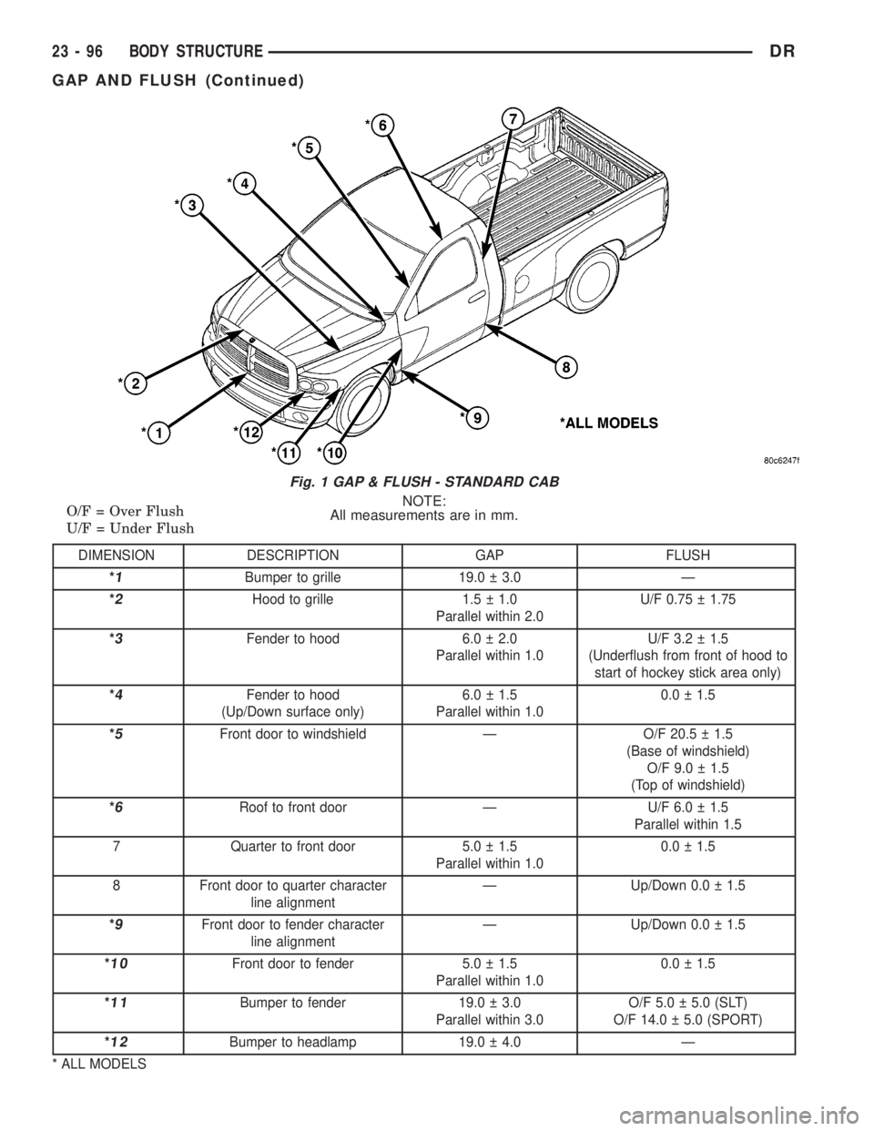
NOTE:
All measurements are in mm. O/F = Over Flush
U/F = Under Flush
DIMENSION DESCRIPTION GAP FLUSH
*
1Bumper to grille 19.0 3.0 Ð
*
2Hood to grille 1.5 1.0
Parallel within 2.0U/F 0.75 1.75
*
3Fender to hood 6.0 2.0
Parallel within 1.0U/F 3.2 1.5
(Underflush from front of hood to
start of hockey stick area only)
*
4Fender to hood
(Up/Down surface only)6.0 1.5
Parallel within 1.00.0 1.5
*
5Front door to windshield Ð O/F 20.5 1.5
(Base of windshield)
O/F 9.0 1.5
(Top of windshield)
*
6Roof to front door Ð U/F 6.0 1.5
Parallel within 1.5
7 Quarter to front door 5.0 1.5
Parallel within 1.00.0 1.5
8 Front door to quarter character
line alignmentÐ Up/Down 0.0 1.5
*
9Front door to fender character
line alignmentÐ Up/Down 0.0 1.5
*
10Front door to fender 5.0 1.5
Parallel within 1.00.0 1.5
*
11Bumper to fender 19.0 3.0
Parallel within 3.0O/F 5.0 5.0 (SLT)
O/F 14.0 5.0 (SPORT)
*
12Bumper to headlamp 19.0 4.0 Ð
* ALL MODELS
Fig. 1 GAP & FLUSH - STANDARD CAB
23 - 96 BODY STRUCTUREDR
GAP AND FLUSH (Continued)