2003 DODGE RAM tire size
[x] Cancel search: tire sizePage 2 of 2895
INTRODUCTION
TABLE OF CONTENTS
page page
VEHICLE SAFETY CERTIFICATION LABEL
DESCRIPTION..........................1
VEHICLE IDENTIFICATION NUMBER
DESCRIPTION..........................2
VEHICLE EMISSION CONTROL INFORMATION
(VECI)
DESCRIPTION..........................3
BODY CODE PLATE
DESCRIPTION..........................4
INTERNATIONAL VEHICLE CONTROL &
DISPLAY SYMBOLS
DESCRIPTION - INTERNATIONAL SYMBOLS . . . 6FASTENER IDENTIFICATION
DESCRIPTION..........................6
FASTENER USAGE
DESCRIPTION - FASTENER USAGE.........9
THREADED HOLE REPAIR
DESCRIPTION - THREADED HOLE REPAIR....9
METRIC SYSTEM
DESCRIPTION..........................9
TORQUE REFERENCES
DESCRIPTION.........................11
VEHICLE SAFETY
CERTIFICATION LABEL
DESCRIPTION
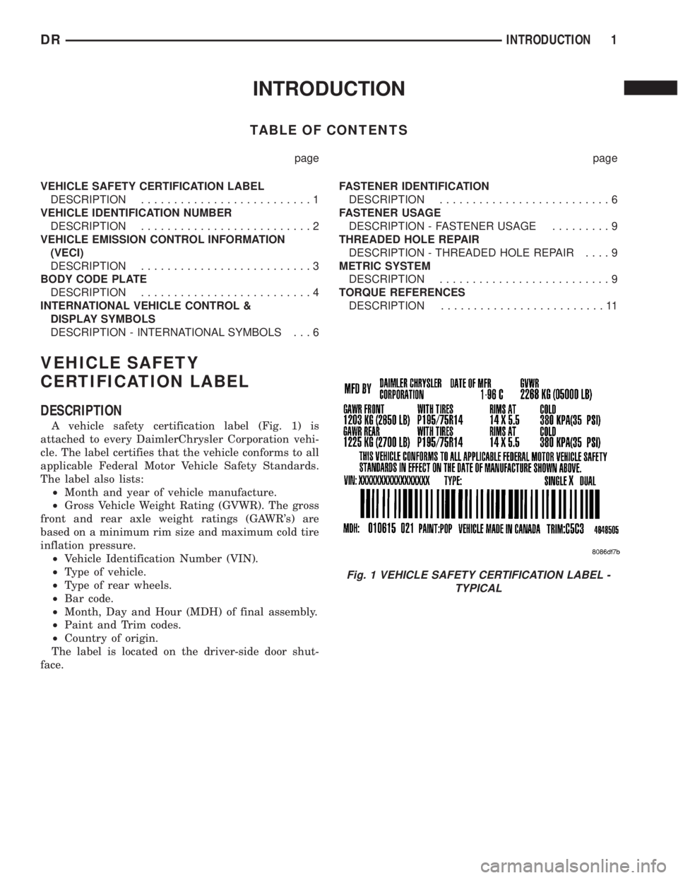
A vehicle safety certification label (Fig. 1) is
attached to every DaimlerChrysler Corporation vehi-
cle. The label certifies that the vehicle conforms to all
applicable Federal Motor Vehicle Safety Standards.
The label also lists:
²Month and year of vehicle manufacture.
²Gross Vehicle Weight Rating (GVWR). The gross
front and rear axle weight ratings (GAWR's) are
based on a minimum rim size and maximum cold tire
inflation pressure.
²Vehicle Identification Number (VIN).
²Type of vehicle.
²Type of rear wheels.
²Bar code.
²Month, Day and Hour (MDH) of final assembly.
²Paint and Trim codes.
²Country of origin.
The label is located on the driver-side door shut-
face.
Fig. 1 VEHICLE SAFETY CERTIFICATION LABEL -
TYPICAL
DRINTRODUCTION 1
Page 31 of 2895
OPERATION
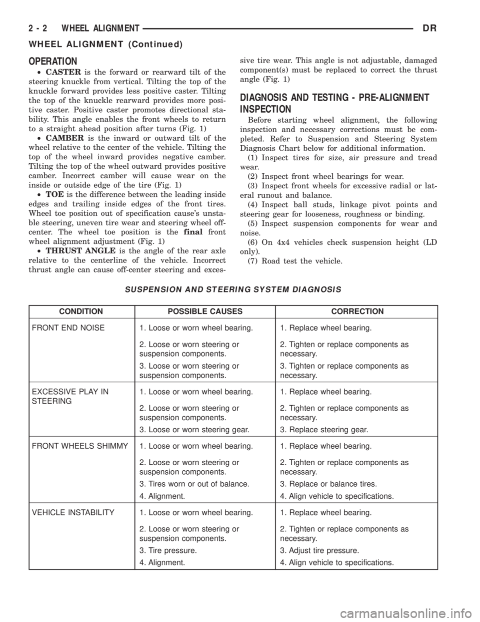
²CASTERis the forward or rearward tilt of the
steering knuckle from vertical. Tilting the top of the
knuckle forward provides less positive caster. Tilting
the top of the knuckle rearward provides more posi-
tive caster. Positive caster promotes directional sta-
bility. This angle enables the front wheels to return
to a straight ahead position after turns (Fig. 1)
²CAMBERis the inward or outward tilt of the
wheel relative to the center of the vehicle. Tilting the
top of the wheel inward provides negative camber.
Tilting the top of the wheel outward provides positive
camber. Incorrect camber will cause wear on the
inside or outside edge of the tire (Fig. 1)
²TOEis the difference between the leading inside
edges and trailing inside edges of the front tires.
Wheel toe position out of specification cause's unsta-
ble steering, uneven tire wear and steering wheel off-
center. The wheel toe position is thefinalfront
wheel alignment adjustment (Fig. 1)
²THRUST ANGLEis the angle of the rear axle
relative to the centerline of the vehicle. Incorrect
thrust angle can cause off-center steering and exces-sive tire wear. This angle is not adjustable, damaged
component(s) must be replaced to correct the thrust
angle (Fig. 1)
DIAGNOSIS AND TESTING - PRE-ALIGNMENT
INSPECTION
Before starting wheel alignment, the following
inspection and necessary corrections must be com-
pleted. Refer to Suspension and Steering System
Diagnosis Chart below for additional information.
(1) Inspect tires for size, air pressure and tread
wear.
(2) Inspect front wheel bearings for wear.
(3) Inspect front wheels for excessive radial or lat-
eral runout and balance.
(4) Inspect ball studs, linkage pivot points and
steering gear for looseness, roughness or binding.
(5) Inspect suspension components for wear and
noise.
(6) On 4x4 vehicles check suspension height (LD
only).
(7) Road test the vehicle.
SUSPENSION AND STEERING SYSTEM DIAGNOSIS
CONDITION POSSIBLE CAUSES CORRECTION
FRONT END NOISE 1. Loose or worn wheel bearing. 1. Replace wheel bearing.
2. Loose or worn steering or
suspension components.2. Tighten or replace components as
necessary.
3. Loose or worn steering or
suspension components.3. Tighten or replace components as
necessary.
EXCESSIVE PLAY IN
STEERING1. Loose or worn wheel bearing. 1. Replace wheel bearing.
2. Loose or worn steering or
suspension components.2. Tighten or replace components as
necessary.
3. Loose or worn steering gear. 3. Replace steering gear.
FRONT WHEELS SHIMMY 1. Loose or worn wheel bearing. 1. Replace wheel bearing.
2. Loose or worn steering or
suspension components.2. Tighten or replace components as
necessary.
3. Tires worn or out of balance. 3. Replace or balance tires.
4. Alignment. 4. Align vehicle to specifications.
VEHICLE INSTABILITY 1. Loose or worn wheel bearing. 1. Replace wheel bearing.
2. Loose or worn steering or
suspension components.2. Tighten or replace components as
necessary.
3. Tire pressure. 3. Adjust tire pressure.
4. Alignment. 4. Align vehicle to specifications.
2 - 2 WHEEL ALIGNMENTDR
WHEEL ALIGNMENT (Continued)
Page 1298 of 2895
(5) Install bearing cap and connecting rod on the
journal and tighten bolts to 27 N´m (20 ft. lbs.) plus a
90É turn. DO NOT rotate crankshaft. Plastigage will
smear, resulting in inaccurate indication.
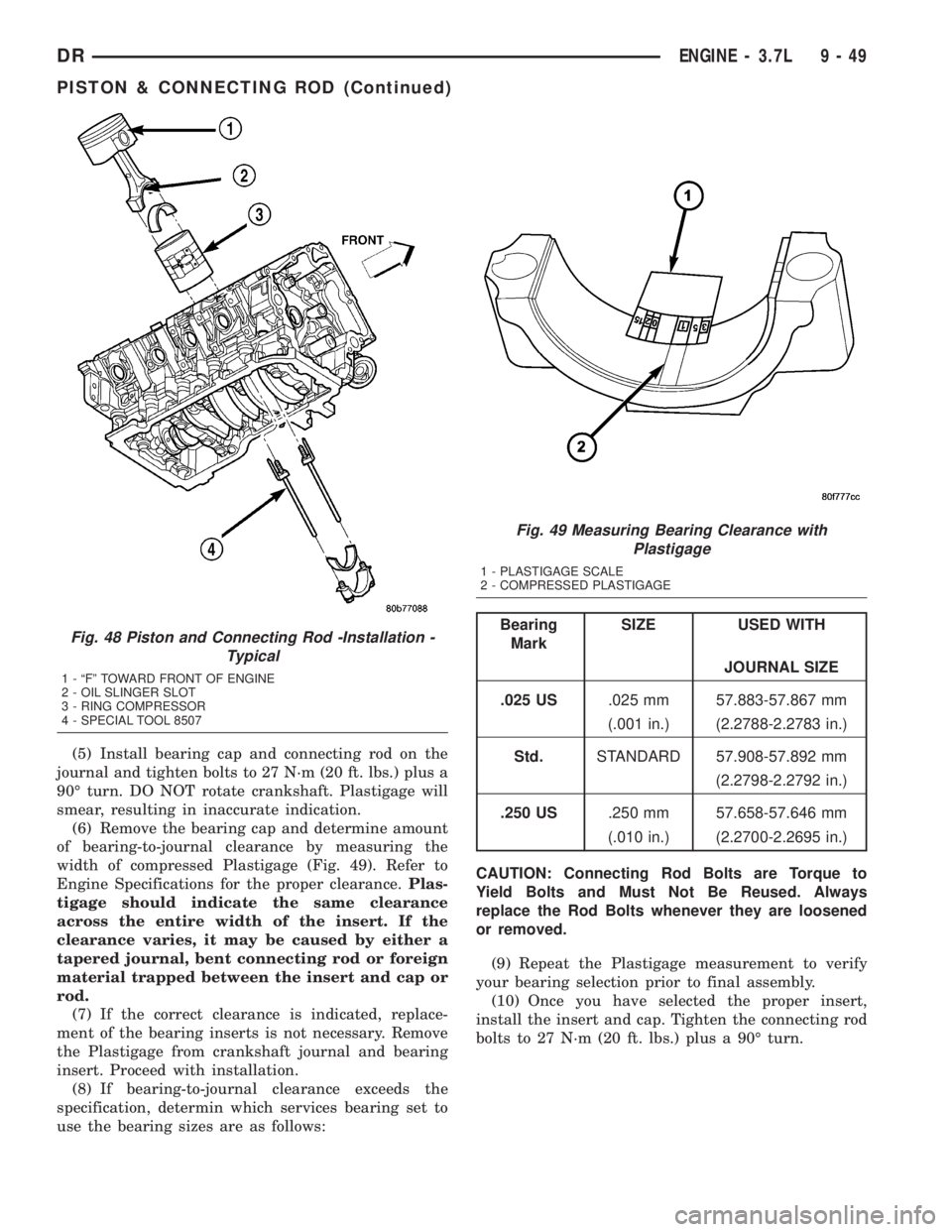
(6) Remove the bearing cap and determine amount
of bearing-to-journal clearance by measuring the
width of compressed Plastigage (Fig. 49). Refer to
Engine Specifications for the proper clearance.Plas-
tigage should indicate the same clearance
across the entire width of the insert. If the
clearance varies, it may be caused by either a
tapered journal, bent connecting rod or foreign
material trapped between the insert and cap or
rod.
(7) If the correct clearance is indicated, replace-
ment of the bearing inserts is not necessary. Remove
the Plastigage from crankshaft journal and bearing
insert. Proceed with installation.
(8) If bearing-to-journal clearance exceeds the
specification, determin which services bearing set to
use the bearing sizes are as follows:
Bearing
MarkSIZE USED WITH
JOURNAL SIZE
.025 US.025 mm 57.883-57.867 mm
(.001 in.) (2.2788-2.2783 in.)
Std.STANDARD 57.908-57.892 mm
(2.2798-2.2792 in.)
.250 US.250 mm 57.658-57.646 mm
(.010 in.) (2.2700-2.2695 in.)
CAUTION: Connecting Rod Bolts are Torque to
Yield Bolts and Must Not Be Reused. Always
replace the Rod Bolts whenever they are loosened
or removed.
(9) Repeat the Plastigage measurement to verify
your bearing selection prior to final assembly.
(10) Once you have selected the proper insert,
install the insert and cap. Tighten the connecting rod
bolts to 27 N´m (20 ft. lbs.) plus a 90É turn.Fig. 48 Piston and Connecting Rod -Installation -
Typical
1 - ªFº TOWARD FRONT OF ENGINE
2 - OIL SLINGER SLOT
3 - RING COMPRESSOR
4 - SPECIAL TOOL 8507
Fig. 49 Measuring Bearing Clearance with
Plastigage
1 - PLASTIGAGE SCALE
2 - COMPRESSED PLASTIGAGE
DRENGINE - 3.7L 9 - 49
PISTON & CONNECTING ROD (Continued)
Page 1579 of 2895
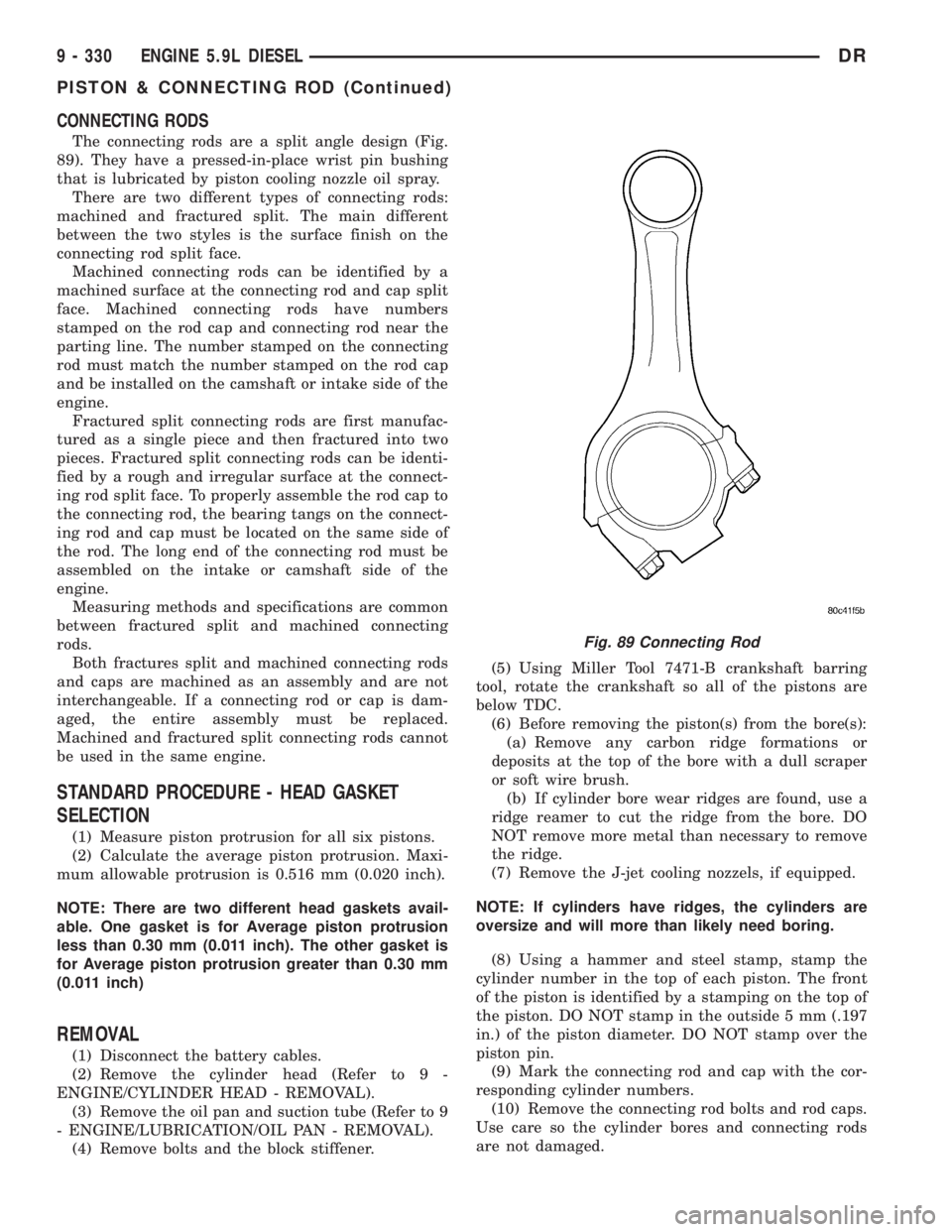
CONNECTING RODS
The connecting rods are a split angle design (Fig.
89). They have a pressed-in-place wrist pin bushing
that is lubricated by piston cooling nozzle oil spray.
There are two different types of connecting rods:
machined and fractured split. The main different
between the two styles is the surface finish on the
connecting rod split face.
Machined connecting rods can be identified by a
machined surface at the connecting rod and cap split
face. Machined connecting rods have numbers
stamped on the rod cap and connecting rod near the
parting line. The number stamped on the connecting
rod must match the number stamped on the rod cap
and be installed on the camshaft or intake side of the
engine.
Fractured split connecting rods are first manufac-
tured as a single piece and then fractured into two
pieces. Fractured split connecting rods can be identi-
fied by a rough and irregular surface at the connect-
ing rod split face. To properly assemble the rod cap to
the connecting rod, the bearing tangs on the connect-
ing rod and cap must be located on the same side of
the rod. The long end of the connecting rod must be
assembled on the intake or camshaft side of the
engine.
Measuring methods and specifications are common
between fractured split and machined connecting
rods.
Both fractures split and machined connecting rods
and caps are machined as an assembly and are not
interchangeable. If a connecting rod or cap is dam-
aged, the entire assembly must be replaced.
Machined and fractured split connecting rods cannot
be used in the same engine.
STANDARD PROCEDURE - HEAD GASKET
SELECTION
(1) Measure piston protrusion for all six pistons.
(2) Calculate the average piston protrusion. Maxi-
mum allowable protrusion is 0.516 mm (0.020 inch).
NOTE: There are two different head gaskets avail-
able. One gasket is for Average piston protrusion
less than 0.30 mm (0.011 inch). The other gasket is
for Average piston protrusion greater than 0.30 mm
(0.011 inch)
REMOVAL
(1) Disconnect the battery cables.
(2) Remove the cylinder head (Refer to 9 -
ENGINE/CYLINDER HEAD - REMOVAL).
(3) Remove the oil pan and suction tube (Refer to 9
- ENGINE/LUBRICATION/OIL PAN - REMOVAL).
(4) Remove bolts and the block stiffener.(5) Using Miller Tool 7471-B crankshaft barring
tool, rotate the crankshaft so all of the pistons are
below TDC.
(6) Before removing the piston(s) from the bore(s):
(a) Remove any carbon ridge formations or
deposits at the top of the bore with a dull scraper
or soft wire brush.
(b) If cylinder bore wear ridges are found, use a
ridge reamer to cut the ridge from the bore. DO
NOT remove more metal than necessary to remove
the ridge.
(7) Remove the J-jet cooling nozzels, if equipped.
NOTE: If cylinders have ridges, the cylinders are
oversize and will more than likely need boring.
(8) Using a hammer and steel stamp, stamp the
cylinder number in the top of each piston. The front
of the piston is identified by a stamping on the top of
the piston. DO NOT stamp in the outside 5 mm (.197
in.) of the piston diameter. DO NOT stamp over the
piston pin.
(9) Mark the connecting rod and cap with the cor-
responding cylinder numbers.
(10) Remove the connecting rod bolts and rod caps.
Use care so the cylinder bores and connecting rods
are not damaged.
Fig. 89 Connecting Rod
9 - 330 ENGINE 5.9L DIESELDR
PISTON & CONNECTING ROD (Continued)
Page 1795 of 2895
DIAGNOSIS AND TESTING
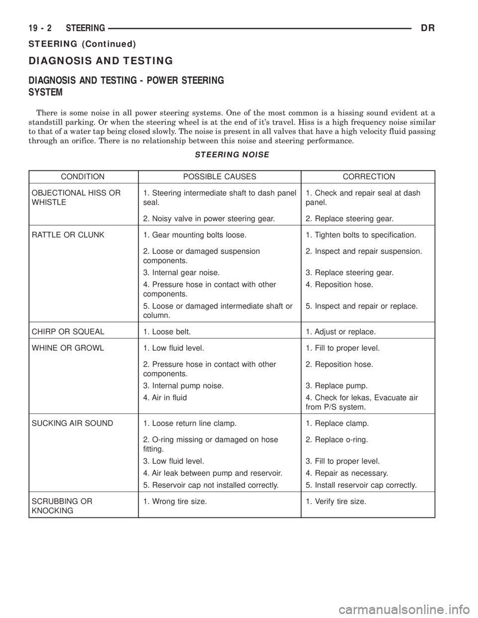
DIAGNOSIS AND TESTING - POWER STEERING
SYSTEM
There is some noise in all power steering systems. One of the most common is a hissing sound evident at a
standstill parking. Or when the steering wheel is at the end of it's travel. Hiss is a high frequency noise similar
to that of a water tap being closed slowly. The noise is present in all valves that have a high velocity fluid passing
through an orifice. There is no relationship between this noise and steering performance.
STEERING NOISE
CONDITION POSSIBLE CAUSES CORRECTION
OBJECTIONAL HISS OR
WHISTLE1. Steering intermediate shaft to dash panel
seal.1. Check and repair seal at dash
panel.
2. Noisy valve in power steering gear. 2. Replace steering gear.
RATTLE OR CLUNK 1. Gear mounting bolts loose. 1. Tighten bolts to specification.
2. Loose or damaged suspension
components.2. Inspect and repair suspension.
3. Internal gear noise. 3. Replace steering gear.
4. Pressure hose in contact with other
components.4. Reposition hose.
5. Loose or damaged intermediate shaft or
column.5. Inspect and repair or replace.
CHIRP OR SQUEAL 1. Loose belt. 1. Adjust or replace.
WHINE OR GROWL 1. Low fluid level. 1. Fill to proper level.
2. Pressure hose in contact with other
components.2. Reposition hose.
3. Internal pump noise. 3. Replace pump.
4. Air in fluid 4. Check for lekas, Evacuate air
from P/S system.
SUCKING AIR SOUND 1. Loose return line clamp. 1. Replace clamp.
2. O-ring missing or damaged on hose
fitting.2. Replace o-ring.
3. Low fluid level. 3. Fill to proper level.
4. Air leak between pump and reservoir. 4. Repair as necessary.
5. Reservoir cap not installed correctly. 5. Install reservoir cap correctly.
SCRUBBING OR
KNOCKING1. Wrong tire size. 1. Verify tire size.
19 - 2 STEERINGDR
STEERING (Continued)
Page 1995 of 2895
STANDARD PROCEDURE - ALUMINUM
THREAD REPAIR
Damaged or worn threads in the aluminum trans-
mission case and valve body can be repaired by the
use of Heli-CoilsŸ, or equivalent. This repair con-
sists of drilling out the worn-out damaged threads.
Then tap the hole with a special Heli-CoilŸ tap, or
equivalent, and installing a Heli-CoilŸ insert, or
equivalent, into the hole. This brings the hole back to
its original thread size.
Heli-CoilŸ, or equivalent, tools and inserts are
readily available from most automotive parts suppli-
ers.
REMOVAL
NOTE: The overdrive unit can be removed and ser-
viced separately. It is not necessary to remove the
entire transmission assembly to perform overdrive
unit repairs.
(1) Disconnect battery negative cable.
(2) Raise vehicle.
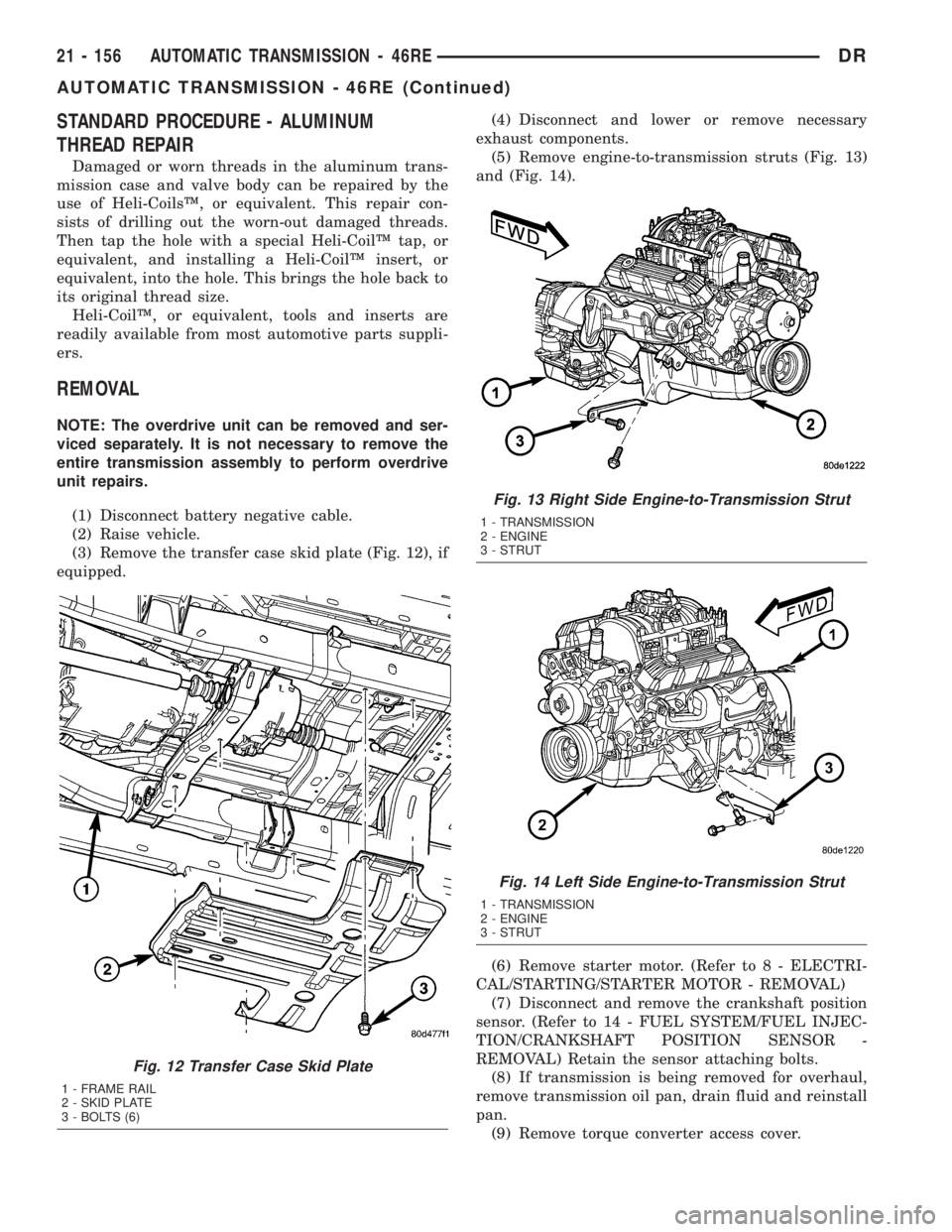
(3) Remove the transfer case skid plate (Fig. 12), if
equipped.(4) Disconnect and lower or remove necessary
exhaust components.
(5) Remove engine-to-transmission struts (Fig. 13)
and (Fig. 14).
(6) Remove starter motor. (Refer to 8 - ELECTRI-
CAL/STARTING/STARTER MOTOR - REMOVAL)
(7) Disconnect and remove the crankshaft position
sensor. (Refer to 14 - FUEL SYSTEM/FUEL INJEC-
TION/CRANKSHAFT POSITION SENSOR -
REMOVAL) Retain the sensor attaching bolts.
(8) If transmission is being removed for overhaul,
remove transmission oil pan, drain fluid and reinstall
pan.
(9) Remove torque converter access cover.
Fig. 12 Transfer Case Skid Plate
1 - FRAME RAIL
2 - SKID PLATE
3 - BOLTS (6)
Fig. 13 Right Side Engine-to-Transmission Strut
1 - TRANSMISSION
2 - ENGINE
3 - STRUT
Fig. 14 Left Side Engine-to-Transmission Strut
1 - TRANSMISSION
2 - ENGINE
3 - STRUT
21 - 156 AUTOMATIC TRANSMISSION - 46REDR
AUTOMATIC TRANSMISSION - 46RE (Continued)
Page 2090 of 2895
(3) Lubricate splined end of input shaft and clutch
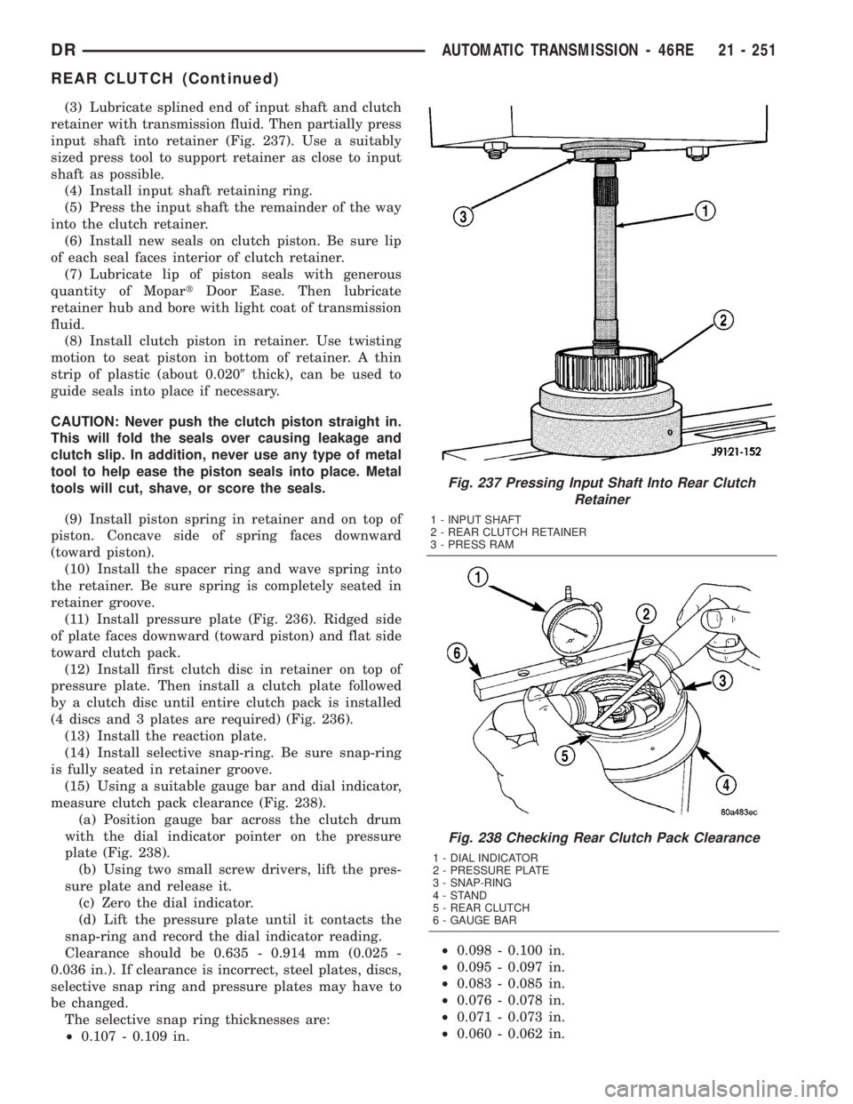
retainer with transmission fluid. Then partially press
input shaft into retainer (Fig. 237). Use a suitably
sized press tool to support retainer as close to input
shaft as possible.
(4) Install input shaft retaining ring.
(5) Press the input shaft the remainder of the way
into the clutch retainer.
(6) Install new seals on clutch piston. Be sure lip
of each seal faces interior of clutch retainer.
(7) Lubricate lip of piston seals with generous
quantity of MopartDoor Ease. Then lubricate
retainer hub and bore with light coat of transmission
fluid.
(8) Install clutch piston in retainer. Use twisting
motion to seat piston in bottom of retainer. A thin
strip of plastic (about 0.0209thick), can be used to
guide seals into place if necessary.
CAUTION: Never push the clutch piston straight in.
This will fold the seals over causing leakage and
clutch slip. In addition, never use any type of metal
tool to help ease the piston seals into place. Metal
tools will cut, shave, or score the seals.
(9) Install piston spring in retainer and on top of
piston. Concave side of spring faces downward
(toward piston).
(10) Install the spacer ring and wave spring into
the retainer. Be sure spring is completely seated in
retainer groove.
(11) Install pressure plate (Fig. 236). Ridged side
of plate faces downward (toward piston) and flat side
toward clutch pack.
(12) Install first clutch disc in retainer on top of
pressure plate. Then install a clutch plate followed
by a clutch disc until entire clutch pack is installed
(4 discs and 3 plates are required) (Fig. 236).
(13) Install the reaction plate.
(14) Install selective snap-ring. Be sure snap-ring
is fully seated in retainer groove.
(15) Using a suitable gauge bar and dial indicator,
measure clutch pack clearance (Fig. 238).
(a) Position gauge bar across the clutch drum
with the dial indicator pointer on the pressure
plate (Fig. 238).
(b) Using two small screw drivers, lift the pres-
sure plate and release it.
(c) Zero the dial indicator.
(d) Lift the pressure plate until it contacts the
snap-ring and record the dial indicator reading.
Clearance should be 0.635 - 0.914 mm (0.025 -
0.036 in.). If clearance is incorrect, steel plates, discs,
selective snap ring and pressure plates may have to
be changed.
The selective snap ring thicknesses are:
²0.107 - 0.109 in.²0.098 - 0.100 in.
²0.095 - 0.097 in.
²0.083 - 0.085 in.
²0.076 - 0.078 in.
²0.071 - 0.073 in.
²0.060 - 0.062 in.
Fig. 237 Pressing Input Shaft Into Rear Clutch
Retainer
1 - INPUT SHAFT
2 - REAR CLUTCH RETAINER
3 - PRESS RAM
Fig. 238 Checking Rear Clutch Pack Clearance
1 - DIAL INDICATOR
2 - PRESSURE PLATE
3 - SNAP-RING
4-STAND
5 - REAR CLUTCH
6 - GAUGE BAR
DRAUTOMATIC TRANSMISSION - 46RE 21 - 251
REAR CLUTCH (Continued)
Page 2176 of 2895
STANDARD PROCEDURE - ALUMINUM
THREAD REPAIR
Damaged or worn threads in the aluminum trans-
mission case and valve body can be repaired by the
use of Heli-CoilsŸ, or equivalent. This repair con-
sists of drilling out the worn-out damaged threads.
Then tap the hole with a special Heli-CoilŸ tap, or
equivalent, and installing a Heli-CoilŸ insert, or
equivalent, into the hole. This brings the hole back to
its original thread size.
Heli-CoilŸ, or equivalent, tools and inserts are
readily available from most automotive parts suppli-
ers.
REMOVAL
NOTE: The overdrive unit can be removed and ser-
viced separately. It is not necessary to remove the
entire transmission assembly to perform overdrive
unit repairs.
(1) Disconnect battery negative cable.
(2) Raise vehicle.
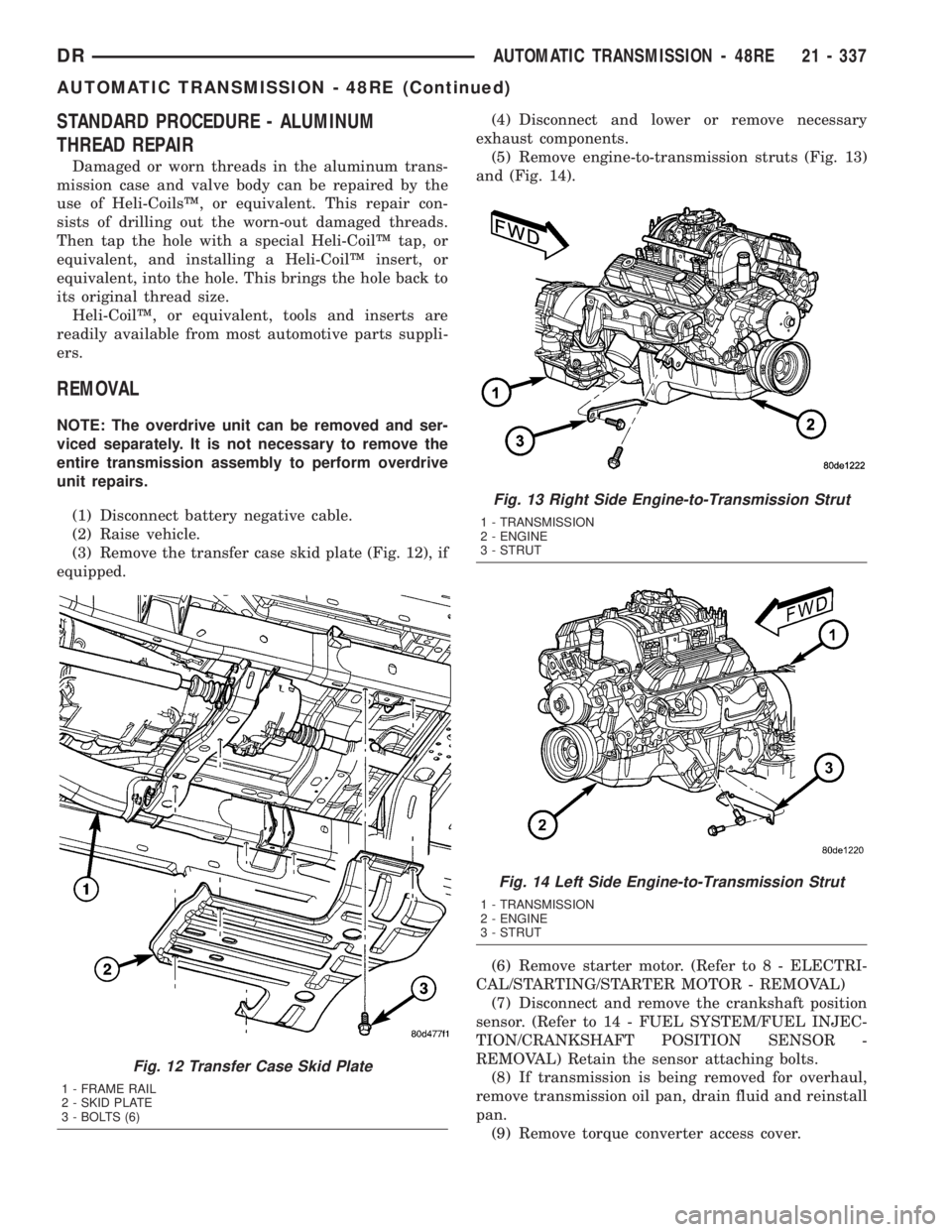
(3) Remove the transfer case skid plate (Fig. 12), if
equipped.(4) Disconnect and lower or remove necessary
exhaust components.
(5) Remove engine-to-transmission struts (Fig. 13)
and (Fig. 14).
(6) Remove starter motor. (Refer to 8 - ELECTRI-
CAL/STARTING/STARTER MOTOR - REMOVAL)
(7) Disconnect and remove the crankshaft position
sensor. (Refer to 14 - FUEL SYSTEM/FUEL INJEC-
TION/CRANKSHAFT POSITION SENSOR -
REMOVAL) Retain the sensor attaching bolts.
(8) If transmission is being removed for overhaul,
remove transmission oil pan, drain fluid and reinstall
pan.
(9) Remove torque converter access cover.
Fig. 12 Transfer Case Skid Plate
1 - FRAME RAIL
2 - SKID PLATE
3 - BOLTS (6)
Fig. 13 Right Side Engine-to-Transmission Strut
1 - TRANSMISSION
2 - ENGINE
3 - STRUT
Fig. 14 Left Side Engine-to-Transmission Strut
1 - TRANSMISSION
2 - ENGINE
3 - STRUT
DRAUTOMATIC TRANSMISSION - 48RE 21 - 337
AUTOMATIC TRANSMISSION - 48RE (Continued)