2003 DODGE RAM tire size
[x] Cancel search: tire sizePage 2560 of 2895
TIRES/WHEELS
TABLE OF CONTENTS
page page
TIRES/WHEELS
DIAGNOSIS AND TESTING - TIRE AND
WHEEL RUNOUT......................1
STANDARD PROCEDURE
STANDARD PROCEDURE - TIRE ROTATION . 2
STANDARD PROCEDURE - MATCH
MOUNTING...........................3
STANDARD PROCEDURE - TIRE AND
WHEEL BALANCE......................4
TIRES
DESCRIPTION
DESCRIPTION - SPARE TIRE /
TEMPORARY.........................5
DESCRIPTION - TIRES..................5
DESCRIPTION - RADIAL ± PLY TIRES......6
DESCRIPTION - TIRE PRESSURE FOR
HIGH SPEEDS.........................6
DESCRIPTION - REPLACEMENT TIRES.....6
DESCRIPTION - TIRE INFLATION
PRESSURES..........................6
DIAGNOSIS AND TESTING
DIAGNOSIS AND TESTING - PRESSURE
GAUGES.............................7
DIAGNOSIS AND TESTING - TIRE NOISE
OR VIBRATION........................7
DIAGNOSIS AND TESTING - TREAD WEAR
INDICATORS..........................7
DIAGNOSIS AND TESTING - TIRE WEAR
PATTERNS...........................8
DIAGNOSIS AND TESTING - TIRE/VEHICLE
LEAD................................8STANDARD PROCEDURE - REPAIRING
LEAKS..............................10
SPECIFICATIONS
TIRE REVOLUTIONS PER MILE..........10
WHEELS
DESCRIPTION.........................11
OPERATION...........................11
DIAGNOSIS AND TESTING
WHEEL INSPECTION..................11
STANDARD PROCEDURE
STANDARD PROCEDURE - WHEEL
REPLACEMENT.......................12
STANDARD PROCEDURE - DUAL REAR
WHEEL INSTALLATION.................12
SPECIFICATIONS
TORQUE CHART......................13
STUDS
REMOVAL.............................14
INSTALLATION.........................14
WHEEL COVER
REMOVAL.............................14
INSTALLATION
INSTALLATION - REAR.................14
INSTALLATION - FRONT................15
SPARE TIRE
DESCRIPTION
DESCRIPTION - SPARE / TEMPORARY
TIRE...............................15
DESCRIPTION - FULL SIZE, SPARE WHEEL
WITH MATCHING TIRE.................15
TIRES/WHEELS
DIAGNOSIS AND TESTING - TIRE AND WHEEL
RUNOUT
Radial runout is the difference between the high
and low points on the tire or wheel (Fig. 1).
Lateral runout is thewobbleof the tire or wheel.
Radial runout of more than 1.5 mm (.060 inch)
measured at the center line of the tread may cause
the vehicle to shake.
Lateral runout of more than 2.0 mm (.080 inch)
measured near the shoulder of the tire may cause the
vehicle to shake.
Sometimes radial runout can be reduced. Relocate
the wheel and tire assembly on the mounting studs
(See Method 1). If this does not reduce runout to anacceptable level, the tire can be rotated on the wheel.
(See Method 2).
METHOD 1 (RELOCATE WHEEL ON HUB)
(1) Drive vehicle a short distance to eliminate tire
flat spotting from a parked position.
(2) Check wheel bearings and adjust if adjustable
or replace if necessary.
(3) Check the wheel mounting surface.
(4) Relocate wheel on the mounting, two studs
over from the original position.
(5) Tighten wheel nuts until all are properly
torqued, to eliminate brake distortion.
(6) Check radial runout. If still excessive, mark
tire sidewall, wheel, and stud at point of maximum
runout and proceed to Method 2.
DRTIRES/WHEELS 22 - 1
Page 2564 of 2895
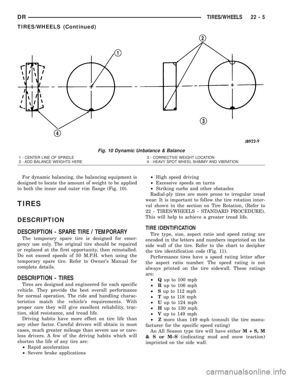
For dynamic balancing, the balancing equipment is
designed to locate the amount of weight to be applied
to both the inner and outer rim flange (Fig. 10).
TIRES
DESCRIPTION
DESCRIPTION - SPARE TIRE / TEMPORARY
The temporary spare tire is designed for emer-
gency use only. The original tire should be repaired
or replaced at the first opportunity, then reinstalled.
Do not exceed speeds of 50 M.P.H. when using the
temporary spare tire. Refer to Owner's Manual for
complete details.
DESCRIPTION - TIRES
Tires are designed and engineered for each specific
vehicle. They provide the best overall performance
for normal operation. The ride and handling charac-
teristics match the vehicle's requirements. With
proper care they will give excellent reliability, trac-
tion, skid resistance, and tread life.
Driving habits have more effect on tire life than
any other factor. Careful drivers will obtain in most
cases, much greater mileage than severe use or care-
less drivers. A few of the driving habits which will
shorten the life of any tire are:
²Rapid acceleration
²Severe brake applications²High speed driving
²Excessive speeds on turns
²Striking curbs and other obstacles
Radial-ply tires are more prone to irregular tread
wear. It is important to follow the tire rotation inter-
val shown in the section on Tire Rotation, (Refer to
22 - TIRES/WHEELS - STANDARD PROCEDURE).
This will help to achieve a greater tread life.
TIRE IDENTIFICATION
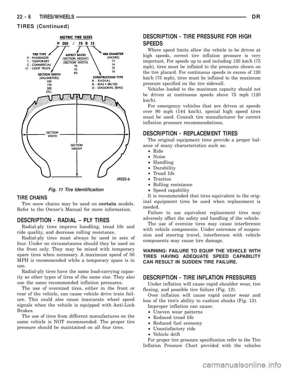
Tire type, size, aspect ratio and speed rating are
encoded in the letters and numbers imprinted on the
side wall of the tire. Refer to the chart to decipher
the tire identification code (Fig. 11).
Performance tires have a speed rating letter after
the aspect ratio number. The speed rating is not
always printed on the tire sidewall. These ratings
are:
²Qup to 100 mph
²Rup to 106 mph
²Sup to 112 mph
²Tup to 118 mph
²Uup to 124 mph
²Hup to 130 mph
²Vup to 149 mph
²Zmore than 149 mph (consult the tire manu-
facturer for the specific speed rating)
An All Season type tire will have eitherM+S,M
&SorM±S(indicating mud and snow traction)
imprinted on the side wall.
Fig. 10 Dynamic Unbalance & Balance
1 - CENTER LINE OF SPINDLE
2 - ADD BALANCE WEIGHTS HERE3 - CORRECTIVE WEIGHT LOCATION
4 - HEAVY SPOT WHEEL SHIMMY AND VIBRATION
DRTIRES/WHEELS 22 - 5
TIRES/WHEELS (Continued)
Page 2565 of 2895
TIRE CHAINS
Tire snow chains may be used oncertainmodels.
Refer to the Owner's Manual for more information.
DESCRIPTION - RADIAL ± PLY TIRES
Radial-ply tires improve handling, tread life and
ride quality, and decrease rolling resistance.
Radial-ply tires must always be used in sets of
four. Under no circumstances should they be used on
the front only. They may be mixed with temporary
spare tires when necessary. A maximum speed of 50
MPH is recommended while a temporary spare is in
use.
Radial-ply tires have the same load-carrying capac-
ity as other types of tires of the same size. They also
use the same recommended inflation pressures.
The use of oversized tires, either in the front or
rear of the vehicle, can cause vehicle drive train fail-
ure. This could also cause inaccurate wheel speed
signals when the vehicle is equipped with Anti-Lock
Brakes.
The use of tires from different manufactures on the
same vehicle is NOT recommended. The proper tire
pressure should be maintained on all four tires.
DESCRIPTION - TIRE PRESSURE FOR HIGH
SPEEDS
Where speed limits allow the vehicle to be driven at
high speeds, correct tire inflation pressure is very
important. For speeds up to and including 120 km/h (75
mph), tires must be inflated to the pressures shown on
the tire placard. For continuous speeds in excess of 120
km/h (75 mph), tires must be inflated to the maximum
pressure specified on the tire sidewall.
Vehicles loaded to the maximum capacity should not
be driven at continuous speeds above 75 mph (120
km/h).
For emergency vehicles that are driven at speeds
over 90 mph (144 km/h), special high speed tires
must be used. Consult tire manufacturer for correct
inflation pressure recommendations.
DESCRIPTION - REPLACEMENT TIRES
The original equipment tires provide a proper bal-
ance of many characteristics such as:
²Ride
²Noise
²Handling
²Durability
²Tread life
²Traction
²Rolling resistance
²Speed capability
It is recommended that tires equivalent to the orig-
inal equipment tires be used when replacement is
needed.
Failure to use equivalent replacement tires may
adversely affect the safety and handling of the vehicle.
The use of oversize tires may cause interference
with vehicle components. Under extremes of suspen-
sion and steering travel, interference with vehicle
components may cause tire damage.
WARNING: FAILURE TO EQUIP THE VEHICLE WITH
TIRES HAVING ADEQUATE SPEED CAPABILITY
CAN RESULT IN SUDDEN TIRE FAILURE.
DESCRIPTION - TIRE INFLATION PRESSURES
Under inflation will cause rapid shoulder wear, tire
flexing, and possible tire failure (Fig. 12).
Over inflation will cause rapid center wear and
loss of the tire's ability to cushion shocks (Fig. 13).
Improper inflation can cause:
²Uneven wear patterns
²Reduced tread life
²Reduced fuel economy
²Unsatisfactory ride
²Vehicle drift
For proper tire pressure specification refer to the Tire
Inflation Pressure Chart provided with the vehicles
Fig. 11 Tire Identification
22 - 6 TIRES/WHEELSDR
TIRES (Continued)
Page 2566 of 2895

Owners Manual. A Certification Label on the drivers
side door pillar provides the minimum tire and rim size
for the vehicle. The label also list the cold inflation pres-
sure for these tires at full load operation
Tire pressures have been chosen to provide safe
operation, vehicle stability, and a smooth ride. Tire
pressure should be checked cold once a month. Tire
pressure decreases as the ambient temperature
drops. Check tire pressure frequently when ambient
temperature varies widely.
Tire inflation pressures are cold inflation pressure.
The vehicle must sit for at least 3 hours to obtain the
correct cold inflation pressure reading. Or be driven
less than one mile after sitting for 3 hours. Tire
inflation pressures may increase from 2 to 6 pounds
per square inch (psi) during operation. Do not reduce
this normal pressure build-up.
WARNING: OVER OR UNDER INFLATED TIRES CAN
AFFECT VEHICLE HANDLING AND TREAD WEAR.
THIS MAY CAUSE THE TIRE TO FAIL SUDDENLY,
RESULTING IN LOSS OF VEHICLE CONTROL.
DIAGNOSIS AND TESTING
DIAGNOSIS AND TESTING - PRESSURE
GAUGES
A quality air pressure gauge is recommended to
check tire pressure. After checking the air pressure,
replace valve cap finger tight.
DIAGNOSIS AND TESTING - TIRE NOISE OR
VIBRATION
Radial-ply tires are sensitive to force impulses
caused by improper mounting, vibration, wheel
defects, or possibly tire imbalance.
To find out if tires are causing the noise or vibra-
tion, drive the vehicle over a smooth road at varying
speeds. Note the noise level during acceleration and
deceleration. The engine, differential and exhaust
noises will change as speed varies, while the tire
noise will usually remain constant.
DIAGNOSIS AND TESTING - TREAD WEAR
INDICATORS
Tread wear indicators are molded into the bottom
of the tread grooves. When tread depth is 1.6 mm
(1/16 in.), the tread wear indicators will appear as a
13 mm (1/2 in.) band (Fig. 14).
Tire replacement is necessary when indicators
appear in two or more grooves or if localized balding
occurs.
Fig. 12 Under Inflation Wear
1 - THIN TIRE THREAD AREAS
Fig. 13 Over Inflation Wear
1 - THIN TIRE THREAD AREA
Fig. 14 Tread Wear Indicators
1 - TREAD ACCEPTABLE
2 - TREAD UNACCEPTABLE
3 - WEAR INDICATOR
DRTIRES/WHEELS 22 - 7
TIRES (Continued)
Page 2569 of 2895
STANDARD PROCEDURE - REPAIRING LEAKS
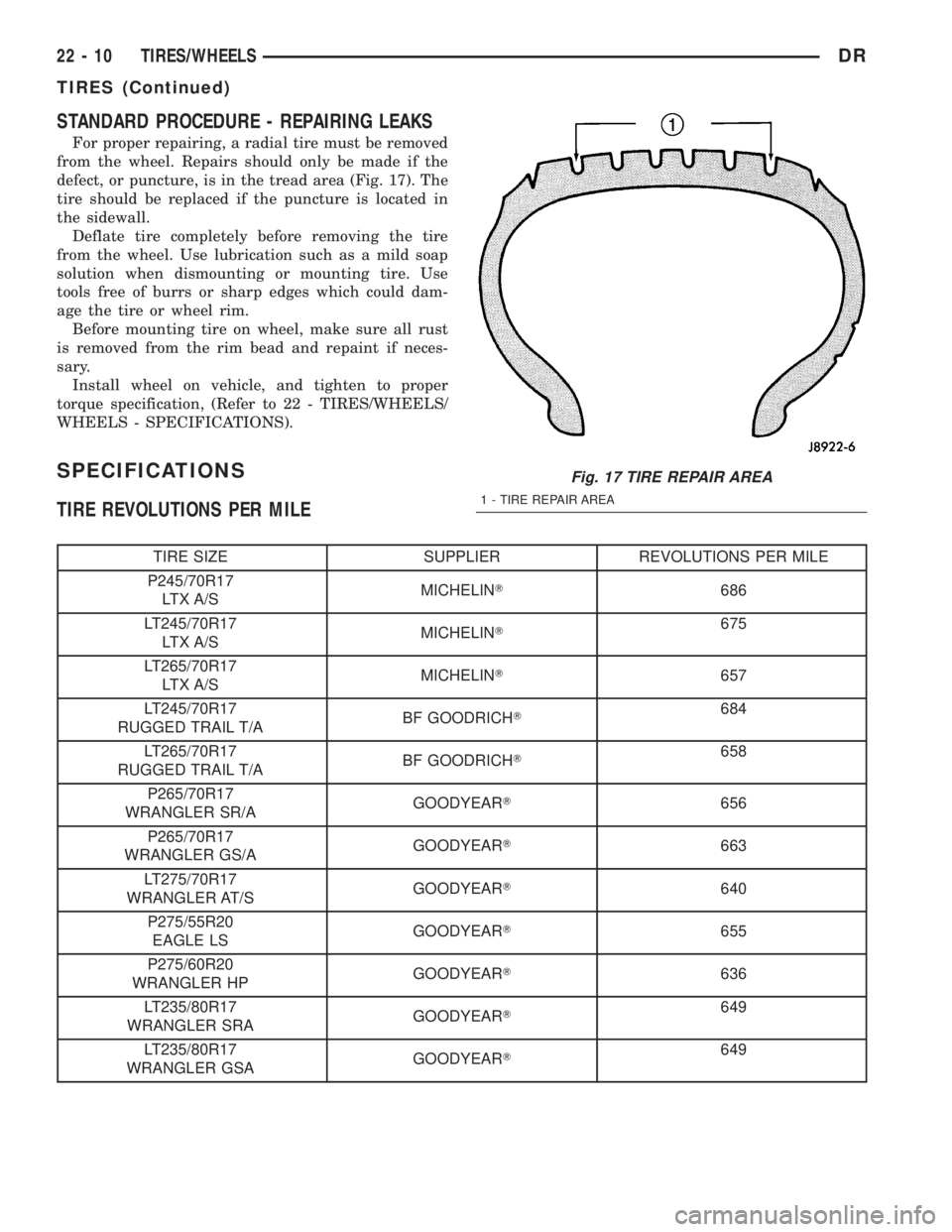
For proper repairing, a radial tire must be removed
from the wheel. Repairs should only be made if the
defect, or puncture, is in the tread area (Fig. 17). The
tire should be replaced if the puncture is located in
the sidewall.
Deflate tire completely before removing the tire
from the wheel. Use lubrication such as a mild soap
solution when dismounting or mounting tire. Use
tools free of burrs or sharp edges which could dam-
age the tire or wheel rim.
Before mounting tire on wheel, make sure all rust
is removed from the rim bead and repaint if neces-
sary.
Install wheel on vehicle, and tighten to proper
torque specification, (Refer to 22 - TIRES/WHEELS/
WHEELS - SPECIFICATIONS).
SPECIFICATIONS
TIRE REVOLUTIONS PER MILE
TIRE SIZE SUPPLIER REVOLUTIONS PER MILE
P245/70R17
LTX A/SMICHELINT686
LT245/70R17
LTX A/SMICHELINT675
LT265/70R17
LTX A/SMICHELINT657
LT245/70R17
RUGGED TRAIL T/ABF GOODRICHT684
LT265/70R17
RUGGED TRAIL T/ABF GOODRICHT658
P265/70R17
WRANGLER SR/AGOODYEART656
P265/70R17
WRANGLER GS/AGOODYEART663
LT275/70R17
WRANGLER AT/SGOODYEART640
P275/55R20
EAGLE LSGOODYEART655
P275/60R20
WRANGLER HPGOODYEART636
LT235/80R17
WRANGLER SRAGOODYEART649
LT235/80R17
WRANGLER GSAGOODYEART649
Fig. 17 TIRE REPAIR AREA
1 - TIRE REPAIR AREA
22 - 10 TIRES/WHEELSDR
TIRES (Continued)
Page 2574 of 2895
(4) Tug on the hub/cap wheel skin to ensure that
they are properly installed.
INSTALLATION - FRONT
(1) Align the valve stem with the notch in the
wheel skin.
(2) Seat on side of the wheel skin's wire retainer
on to the wheel.
(3) Using a rubber mallet, strike the opposite side
of the wheel skin until the skin is properly seated.
NOTE: The wheel skin and the hub cap are fully
seated when there is a consistant gap between the
skin/ cap and the wheel.
(4) Tug on the hub cap/wheel skin to ensure that
they are properly installed.
SPARE TIRE
DESCRIPTION
DESCRIPTION - SPARE / TEMPORARY TIRE
The temporary spare tire is designed for emer-
gency use only. The original tire should be repaired
or replaced at the first opportunity, then reinstalled.
Do not exceed speeds of 50 M.P.H. when using the
temporary spare tire. Refer to Owner's Manual for
complete details.
DESCRIPTION - FULL SIZE, SPARE WHEEL
WITH MATCHING TIRE
The spare is a full usage wheel with a matching
tire, It can be used within the (posted legal) speed
limits or distance limitations as of the rest of the
vehicles four tires. Refer to Owner's Manual for com-
plete details.
DRTIRES/WHEELS 22 - 15
WHEEL COVER (Continued)
Page 2808 of 2895
CAUTION
SERVICE CAUTIONS
CAUTION: Liquid refrigerant is corrosive to metal
surfaces. Follow the operating instructions supplied
with the service equipment being used.
Never add R-12 to a refrigerant system designed to
use R-134a. Damage to the system will result.
R-12 refrigerant oil must not be mixed with R-134a
refrigerant oil. They are not compatible.
Do not use R-12 equipment or parts on the R-134a
system. Damage to the system will result.
Do not overcharge the refrigerant system. This will
cause excessive compressor head pressure and
can cause noise and system failure.
Recover the refrigerant before opening any fitting
or connection. Open the fittings with caution, even
after the system has been discharged. Never open
or loosen a connection before recovering the refrig-
erant.
Do not remove the secondary retention clip from
any spring-lock coupler connection while the refrig-
erant system is under pressure. Recover the refrig-
erant before removing the secondary retention clip.
Open the fittings with caution, even after the sys-
tem has been discharged. Never open or loosen a
connection before recovering the refrigerant.
The refrigerant system must always be evacuated
before charging.
Do not open the refrigerant system or uncap a
replacement component until you are ready to ser-
vice the system. This will prevent contamination in
the system.
Before disconnecting a component, clean the out-
side of the fittings thoroughly to prevent contami-
nation from entering the refrigerant system.
Immediately after disconnecting a component from
the refrigerant system, seal the open fittings with a
cap or plug.
Before connecting an open refrigerant fitting,
always install a new seal or gasket. Coat the fitting
and seal with clean refrigerant oil before connect-
ing.
Do not remove the sealing caps from a replacement
component until it is to be installed.
When installing a refrigerant line, avoid sharp
bends that may restrict refrigerant flow. Position the
refrigerant lines away from exhaust system compo-
nents or any sharp edges, which may damage the
line.
Tighten refrigerant fittings only to the specified
torque. The aluminum fittings used in the refriger-
ant system will not tolerate overtightening.
When disconnecting a refrigerant fitting, use a
wrench on both halves of the fitting. This will pre-vent twisting of the refrigerant lines or tubes.
Refrigerant oil will absorb moisture from the atmo-
sphere if left uncapped. Do not open a container of
refrigerant oil until you are ready to use it. Replace
the cap on the oil container immediately after using.
Store refrigerant oil only in a clean, airtight, and
moisture-free container.
Keep service tools and the work area clean. Con-
tamination of the refrigerant system through care-
less work habits must be avoided.
CAUTION - REFRIGERANT HOSES/LINES/
TUBES PRECAUTIONS
Kinks or sharp bends in the refrigerant plumbing
will reduce the capacity of the entire system. High
pressures are produced in the system when it is oper-
ating. Extreme care must be exercised to make sure
that all refrigerant system connections are pressure
tight.
A good rule for the flexible hose refrigerant lines is
to keep the radius of all bends at least ten times the
diameter of the hose. Sharp bends will reduce the
flow of refrigerant. The flexible hose lines should be
routed so they are at least 80 millimeters (3 inches)
from the exhaust manifold. It is a good practice to
inspect all flexible refrigerant system hose lines at
least once a year to make sure they are in good con-
dition and properly routed.
There are two types of refrigerant fittings:
²All fittings with O-rings need to be coated with
refrigerant oil before installation. Use only O-rings
that are the correct size and approved for use with
R-134a refrigerant. Failure to do so may result in a
leak.
²Unified plumbing connections with gaskets can-
not be serviced with O-rings. The gaskets are not
reusable and new gaskets do not require lubrication
before installing.
Using the proper tools when making a refrigerant
plumbing connection is very important. Improper
tools or improper use of the tools can damage the
refrigerant fittings. Always use two wrenches when
loosening or tightening tube fittings. Use one wrench
to hold one side of the connection stationary, while
loosening or tightening the other side of the connec-
tion with a second wrench.
The refrigerant must be recovered completely from
the system before opening any fitting or connection.
Open the fittings with caution, even after the refrig-
erant has been recovered. If any pressure is noticed
as a fitting is loosened, tighten the fitting and
recover the refrigerant from the system again.
Do not discharge refrigerant into the atmosphere.
Use an R-134a refrigerant recovery/recycling device
that meets SAE Standard J2210.
DRPLUMBING 24 - 33
PLUMBING (Continued)
Page 2870 of 2895
FUEL INJECTOR RAIL - DESCRIPTION....14-89
FUEL INJECTOR RAIL - INSTALLATION....14-90
FUEL INJECTOR RAIL - OPERATION......14-89
FUEL INJECTOR RAIL - REMOVAL.......14-89
FUEL LEVEL SENDING UNIT / SENSOR -
DESCRIPTION...................14-68,14-7
FUEL LEVEL SENDING UNIT / SENSOR -
INSTALLATION........................14-8
FUEL LEVEL SENDING UNIT / SENSOR -
OPERATION.....................14-68,14-7
FUEL LEVEL SENDING UNIT / SENSOR -
REMOVAL...........................14-7
FUEL LINE LEAKS - DIAGNOSIS AND
TESTING, HIGH-PRESSURE.............14-69
FUEL LINES - DESCRIPTION........14-69,14-8
FUEL LINES - INSTALLATION...........14-71
FUEL LINES - OPERATION..............14-69
FUEL LINES - REMOVAL...............14-69
FUEL PRESSURE LIMITING VALVE -
DESCRIPTION.......................14-72
FUEL PRESSURE LIMITING VALVE -
INSTALLATION.......................14-73
FUEL PRESSURE LIMITING VALVE -
OPERATION.........................14-72
FUEL PRESSURE LIMITING VALVE -
REMOVAL..........................14-72
FUEL PRESSURE SENSOR -
DESCRIPTION.......................14-72
FUEL PRESSURE SENSOR -
INSTALLATION.......................14-72
FUEL PRESSURE SENSOR - OPERATION....14-72
FUEL PRESSURE SENSOR - REMOVAL....14-72
FUEL PUMP - DESCRIPTION............14-12
FUEL PUMP - OPERATION.............14-12
FUEL PUMP MODULE - DESCRIPTION....14-12
FUEL PUMP MODULE - INSTALLATION . . . 14-13
FUEL PUMP MODULE - OPERATION......14-12
FUEL PUMP MODULE - REMOVAL.......14-12
FUEL PUMP RELAY - DESCRIPTION......14-33
FUEL PUMP RELAY - INSTALLATION.....14-33
FUEL PUMP RELAY - OPERATION........14-33
FUEL PUMP RELAY - REMOVAL.........14-33
FUEL PUMP RELAYS - DIAGNOSIS AND
TESTING, ASD........................8I-7
FUEL RAIL - DESCRIPTION.............14-13
FUEL RAIL - INSTALLATION............14-18
FUEL RAIL - OPERATION...............14-13
FUEL RAIL - REMOVAL................14-13
FUEL REQUIREMENTS - DIESEL ENGINE
- DESCRIPTION........................0-1
FUEL SENSOR - DESCRIPTION, WATER
IN ................................14-77
FUEL SENSOR - OPERATION, WATER IN . . 14-78
FUEL SENSOR - REMOVAL, WATER IN....14-78
FUEL SYSTEM - DESCRIPTION, DIESEL . . . 14-57
FUEL SYSTEM - TORQUE...............14-3
FUEL SYSTEM PARTS - STANDARD
PROCEDURES, CLEANING..............14-58
FUEL SYSTEM PRESSURE, DIESEL.......14-60
FUEL SYSTEM PRESSURE RELEASE -
STANDARD PROCEDURE................14-2
FUEL SYSTEM PRESSURE,
SPECIFICATIONS......................14-3
FUEL SYSTEM PRIMING - STANDARD
PROCEDURE........................14-59
FUEL SYSTEM, SPECIAL TOOLS..........14-5
FUEL SYSTEM, SPECIAL TOOLS -
DIESEL............................14-60
FUEL TANK - DESCRIPTION............14-20
FUEL TANK - OPERATION..............14-20
FUEL TANK MODULE - DESCRIPTION.....14-75
FUEL TANK MODULE - INSTALLATION....14-75
FUEL TANK MODULE - OPERATION......14-75
FUEL TANK MODULE - REMOVAL........14-75
FUEL TRANSFER PUMP - DESCRIPTION . . 14-75
FUEL TRANSFER PUMP - INSTALLATION . . 14-76
FUEL TRANSFER PUMP - OPERATION....14-76
FUEL TRANSFER PUMP - REMOVAL......14-76
FULL SIZE, SPARE WHEEL WITH
MATCHING TIRE - DESCRIPTION........22-15
FUNCTIONS - DESCRIPTION, CIRCUIT . . 8W-01-6
FUSE - DESCRIPTION, IOD
...........8W-97-6
FUSE - INSTALLATION, IOD
..........8W-97-7
FUSE - OPERATION, IOD
.............8W-97-6
FUSE - REMOVAL, IOD
..............8W-97-6
FUSES POWERING SEVERAL LOADS -
STANDARD PROCEDURE, TESTING
FOR A SHORT TO GROUND ON
......8W-01-10GAP AND FLUSH - SPECIFICATIONS......23-95
GAS - DESCRIPTION, FUEL DELIVERY.....14-1
GAS - INSTALLATION............19-30,19-41
GAS - OPERATION, FUEL DELIVERY.......14-2
GAS - REMOVAL................19-29,19-40
GAS ENGINE - DIAGNOSIS AND TESTING . . 11-2
GAS ENGINE - INSTALLATION...........19-24
GAS ENGINE - REMOVAL..............19-23
GASKET - DESCRIPTION, CYLINDER
HEAD COVER........................9-243
GASKET - DIAGNOSIS AND TESTING,
CYLINDER HEAD......................9-20
GASKET - OPERATION, CYLINDER HEAD
COVER.............................9-243
GASKET FAILURE - DIAGNOSIS AND
TESTING, CYLINDER HEAD . . . 9-194,9-243,9-370
GASKET SELECTION - STANDARD
PROCEDURE, HEAD...................9-330
GASKET SURFACE PREPARATION -
STANDARD PROCEDURE, ENGINE........9-10
GASKETS AND SEALERS - STANDARD
PROCEDURE, FORM-IN-PLACE....9-232,9-289,
9-360,9-9,9-93
GAUGE - DESCRIPTION, ENGINE
TEMPERATURE......................8J-23
GAUGE - DESCRIPTION, FUEL...........8J-25
GAUGE - DESCRIPTION, OIL PRESSURE . . 8J-32
GAUGE - DESCRIPTION, VOLTAGE.......8J-40
GAUGE - OPERATION, ENGINE
TEMPERATURE......................8J-23
GAUGE - OPERATION, FUEL............8J-26
GAUGE - OPERATION, OIL PRESSURE....8J-32
GAUGE - OPERATION, VOLTAGE.........8J-41
GAUGES - DIAGNOSIS AND TESTING,
PRESSURE..........................22-7
GAUGES INDICATOR - DESCRIPTION,
CHECK.............................8J-21
GAUGES INDICATOR - OPERATION,
CHECK.............................8J-21
GEAR - DESCRIPTION, CRANKSHAFT.....9-322
GEAR - INDEPENDENT FRONT
SUSPENSION - DESCRIPTION...........19-16
GEAR - INDEPENDENT FRONT
SUSPENSION - INSTALLATION..........19-17
GEAR - INDEPENDENT FRONT
SUSPENSION - REMOVAL..............19-16
GEAR - INSTALLATION................9-322
GEAR - INSTALLATION, PINION
GEAR/RING......................3-42,3-66
GEAR - LINK/COIL - DESCRIPTION.......19-19
GEAR - LINK/COIL - INSTALLATION......19-20
GEAR - LINK/COIL - OPERATION........19-19
GEAR - LINK/COIL - REMOVAL..........19-19
GEAR - REMOVAL....................9-322
GEAR - REMOVAL, PINION GEAR/RING....3-40,
3-65
GEAR HOUSING - INSTALLATION........9-349
GEAR HOUSING - REMOVAL............9-348
GEAR HOUSING COVER - INSTALLATION . . 9-350
GEAR HOUSING COVER - REMOVAL.....9-349
GEAR INPUT SHAFT SEAL -
INSTALLATION, STEERING.............19-28
GEAR INPUT SHAFT SEAL - REMOVAL,
STEERING..........................19-25
GEAR SELECTOR INDICATOR -
DESCRIPTION.......................8J-26
GEAR SELECTOR INDICATOR -
OPERATION.........................8J-27
GEAR SHIFT LEVER - INSTALLATION.....19-12
GEAR SHIFT LEVER - REMOVAL.........19-12
GEAR, SPECIAL TOOLS - POWER
STEERING..........................19-22
GEAR, SPECIFICATIONS - POWER
STEERING..........................19-21
GEAR TO COOLER - INSTALLATION,
RETURN HOSE.................19-43,19-44
GEAR TO COOLER - REMOVAL, RETURN
HOSE..............................19-43
GEAR/RING GEAR - INSTALLATION,
PINION
.........................3-42,3-66
GEAR/RING GEAR - REMOVAL, PINION
....3-40,
3-65
GEAR/RING GEAR/TONE RING -
INSTALLATION, PINION
.......3-123,3-150,3-96
GEAR/RING GEAR/TONE RING -
REMOVAL, PINION
..........3-122,3-149,3-94
GEARSHIFT CABLE - DIAGNOSIS AND
TESTING
..............21-209,21-389,21-544GEARSHIFT CABLE - INSTALLATION....21-210,
21-390,21-545
GEARSHIFT CABLE - REMOVAL . . 21-209,21-389,
21-544
GEARSHIFT CABLE, ADJUSTMENTS.....21-211,
21-391,21-546
GEAR/TONE RING - INSTALLATION,
PINION GEAR/RING..........3-123,3-150,3-96
GEAR/TONE RING - REMOVAL, PINION
GEAR/RING................3-122,3-149,3-94
GEARTRAIN - ASSEMBLY, PLANETARY . . . 21-573
GEARTRAIN - CLEANING, PLANETARY . . . 21-573
GEARTRAIN - DESCRIPTION,
PLANETARY........................21-571
GEARTRAIN - DISASSEMBLY,
PLANETARY........................21-573
GEARTRAIN - INSPECTION, PLANETARY . 21-573
GEARTRAIN - OPERATION, PLANETARY . . 21-571
GEARTRAIN/OUTPUT SHAFT -
ASSEMBLY, PLANETARY........21-245,21-423
GEARTRAIN/OUTPUT SHAFT -
DESCRIPTION, PLANETARY......21-242,21-420
GEARTRAIN/OUTPUT SHAFT -
DISASSEMBLY, PLANETARY.....21-243,21-421
GEARTRAIN/OUTPUT SHAFT -
INSPECTION, PLANETARY.......21-245,21-422
GEARTRAIN/OUTPUT SHAFT -
OPERATION, PLANETARY.......21-243,21-420
GENERAL - WARNINGS.............8W-01-7
GENERATOR / CHARGING SYSTEM -
SPECIFICATIONS, TORQUE.............8F-20
GENERATOR - DESCRIPTION.............8F-22
GENERATOR - INSTALLATION...........8F-25
GENERATOR - OPERATION.............8F-22
GENERATOR - REMOVAL...............8F-22
GENERATOR RATINGS, SPECIFICATIONS . . 8F-20
GENII - ASSEMBLY, TRANSFER CASE -
NV241............................21-604
GENII - CLEANING, TRANSFER CASE -
NV241............................21-602
GENII - DESCRIPTION, TRANSFER CASE
- NV241..............................0-4
GENII - DESCRIPTION, TRANSFER CASE
- NV241...........................21-591
GENII - DIAGNOSIS AND TESTING,
TRANSFER CASE - NV241.............21-592
GENII - DISASSEMBLY, TRANSFER CASE
- NV241...........................21-593
GENII - INSPECTION, TRANSFER CASE -
NV241............................21-602
GENII - INSTALLATION, TRANSFER CASE
- NV241...........................21-614
GENII - OPERATION, TRANSFER CASE -
NV241............................21-591
GENII - REMOVAL, TRANSFER CASE -
NV241............................21-593
GENII - TRANSFER CASE, NV241.......21-614
GLASS - INSTALLATION, BACKLITE VENT . 23-87
GLASS - INSTALLATION, DOOR....23-20,23-30
GLASS - INSTALLATION, SIDE VIEW
MIRROR...........................23-44
GLASS - REMOVAL, BACKLITE VENT.....23-87
GLASS - REMOVAL, DOOR........23-20,23-30
GLASS - REMOVAL, SIDE VIEW MIRROR . . 23-42
GLASS RUN CHANNEL - INSTALLATION . . 23-21,
23-31
GLASS RUN CHANNEL - REMOVAL . 23-21,23-30
GLASS RUN WEATHERSTRIP -
INSTALLATION, FRONT DOOR...........23-92
GLASS RUN WEATHERSTRIP -
INSTALLATION, REAR DOOR............23-93
GLASS RUN WEATHERSTRIP -
REMOVAL, FRONT DOOR..............23-92
GLASS RUN WEATHERSTRIP -
REMOVAL, REAR DOOR...............23-93
GLOVE BOX - INSTALLATION...........23-53
GLOVE BOX - REMOVAL...............23-53
GLOVE BOX LAMP/SWITCH -
INSTALLATION.......................8L-25
GLOVE BOX LAMP/SWITCH - REMOVAL . . . 8L-25
GLOVE BOX LATCH - INSTALLATION
.....23-53
GLOVE BOX LATCH - REMOVAL
.........23-53
GOVERNOR - DESCRIPTION,
ELECTRONIC
.................21-196,21-376
GOVERNOR - INSTALLATION,
ELECTRONIC
.................21-199,21-379
GOVERNOR - OPERATION, ELECTRONIC
. 21-196,
21-377
DRINDEX 15
Description Group-Page Description Group-Page Description Group-Page