Page 2448 of 2895
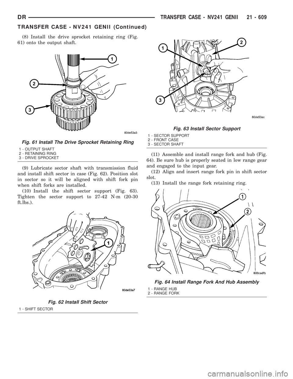
(8) Install the drive sprocket retaining ring (Fig.
61) onto the output shaft.
(9) Lubricate sector shaft with transmission fluid
and install shift sector in case (Fig. 62). Position slot
in sector so it will be aligned with shift fork pin
when shift forks are installed.
(10) Install the shift sector support (Fig. 63).
Tighten the sector support to 27-42 N´m (20-30
ft.lbs.).(11) Assemble and install range fork and hub (Fig.
64). Be sure hub is properly seated in low range gear
and engaged to the input gear.
(12) Align and insert range fork pin in shift sector
slot.
(13) Install the range fork retaining ring.
Fig. 61 Install The Drive Sprocket Retaining Ring
1 - OUTPUT SHAFT
2 - RETAINING RING
3 - DRIVE SPROCKET
Fig. 62 Install Shift Sector
1 - SHIFT SECTOR
Fig. 63 Install Sector Support
1 - SECTOR SUPPORT
2 - FRONT CASE
3 - SECTOR SHAFT
Fig. 64 Install Range Fork And Hub Assembly
1 - RANGE HUB
2 - RANGE FORK
DRTRANSFER CASE - NV241 GENII 21 - 609
TRANSFER CASE - NV241 GENII (Continued)
Page 2451 of 2895
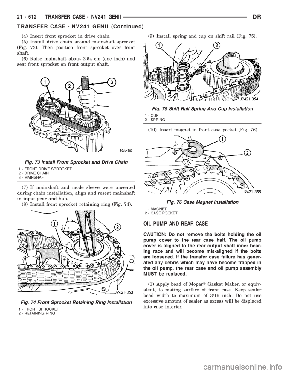
(4) Insert front sprocket in drive chain.
(5) Install drive chain around mainshaft sprocket
(Fig. 73). Then position front sprocket over front
shaft.
(6) Raise mainshaft about 2.54 cm (one inch) and
seat front sprocket on front output shaft.
(7) If mainshaft and mode sleeve were unseated
during chain installation, align and reseat mainshaft
in input gear and hub.
(8) Install front sprocket retaining ring (Fig. 74).(9) Install spring and cup on shift rail (Fig. 75).
(10) Insert magnet in front case pocket (Fig. 76).
OIL PUMP AND REAR CASE
CAUTION: Do not remove the bolts holding the oil
pump cover to the rear case half. The oil pump
cover is aligned to the rear output shaft inner bear-
ing race and will become mis-aligned if the bolts
are loosened. If the transfer case failure has gener-
ated any debris which may have become trapped in
the oil pump. the rear case and oil pump assembly
MUST be replaced.
(1) Apply bead of MopartGasket Maker, or equiv-
alent, to mating surface of front case. Keep sealer
bead width to maximum of 3/16 inch. Do not use
excessive amount of sealer as excess will be displaced
into case interior.
Fig. 73 Install Front Sprocket and Drive Chain
1 - FRONT DRIVE SPROCKET
2 - DRIVE CHAIN
3 - MAINSHAFT
Fig. 74 Front Sprocket Retaining Ring Installation
1 - FRONT SPROCKET
2 - RETAINING RING
Fig. 75 Shift Rail Spring And Cup Installation
1 - CUP
2 - SPRING
Fig. 76 Case Magnet Installation
1 - MAGNET
2 - CASE POCKET
21 - 612 TRANSFER CASE - NV241 GENIIDR
TRANSFER CASE - NV241 GENII (Continued)
Page 2452 of 2895
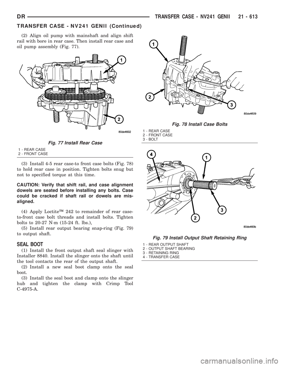
(2) Align oil pump with mainshaft and align shift
rail with bore in rear case. Then install rear case and
oil pump assembly (Fig. 77).
(3) Install 4-5 rear case-to front case bolts (Fig. 78)
to hold rear case in position. Tighten bolts snug but
not to specified torque at this time.
CAUTION: Verify that shift rail, and case alignment
dowels are seated before installing any bolts. Case
could be cracked if shaft rail or dowels are mis-
aligned.
(4) Apply LoctiteŸ 242 to remainder of rear case-
to-front case bolt threads and install bolts. Tighten
bolts to 20-27 N´m (15-24 ft. lbs.),
(5) Install rear output bearing snap-ring (Fig. 79)
to output shaft.
SEAL BOOT
(1) Install the front output shaft seal slinger with
Installer 8840. Install the slinger onto the shaft until
the tool contacts the rear of the output shaft.
(2) Install a new seal boot clamp onto the seal
boot.
(3) Install the seal boot and clamp onto the slinger
hub and tighten the clamp with Crimp Tool
C-4975-A.
Fig. 77 Install Rear Case
1 - REAR CASE
2 - FRONT CASE
Fig. 78 Install Case Bolts
1 - REAR CASE
2 - FRONT CASE
3 - BOLT
Fig. 79 Install Output Shaft Retaining Ring
1 - REAR OUTPUT SHAFT
2 - OUTPUT SHAFT BEARING
3 - RETAINING RING
4 - TRANSFER CASE
DRTRANSFER CASE - NV241 GENII 21 - 613
TRANSFER CASE - NV241 GENII (Continued)
Page 2472 of 2895
(3) Remove the mode hub (Fig. 31) from the main-
shaft.
(4) Remove the drive sprocket drive hub (Fig. 32)
from the mainshaft.INPUT AND PLANETARY GEAR
(1) Remove input gear seal with suitable screw
and slide hammer.
(2) Remove input gear retaining ring (Fig. 33) with
heavy duty snap-ring pliers.
(3) Place front case in horizontal position. Then
remove input gear and low range gear as an assem-
bly (Fig. 34). Tap gear out of bearing with plastic
mallet, if necessary.
Fig. 31 Remove Mode Hub
1 - MAINSHAFT
2 - MODE HUB
Fig. 32 Remove the Drive Sprocket Drive Hub
1 - MAINSHAFT
2 - DRIVE SPROCKET DRIVE HUB
Fig. 33 Remove Input Gear Retaining Ring
1 - INPUT GEAR
2 - RETAINING RING
Fig. 34 Remove Input Planetary Assembly
1 - FRONT CASE
2 - INPUT PLANETARY ASSEMBLY
DRTRANSFER CASE - NV271 21 - 633
TRANSFER CASE - NV271 (Continued)
Page 2475 of 2895
Examine the carrier body and pinion gears for
wear or damage. Check the pinion gear thrust wash-
ers on the pinon pins for damage. The carrier will
have to be replaced as an assembly if the body, pin-
ion pins, or pinion gears are damaged.
Check the lock ring and both thrust washers for
wear or cracks. Replace them if necessary. Also
replace the lock retaining ring if bent, distorted, or
broken.
SHIFT FORKS/HUBS/SLEEVES
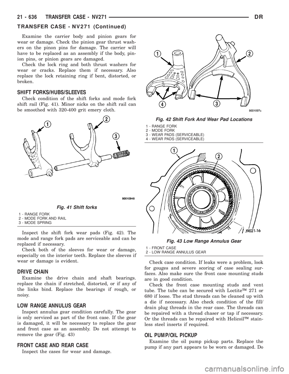
Check condition of the shift forks and mode fork
shift rail (Fig. 41). Minor nicks on the shift rail can
be smoothed with 320-400 grit emery cloth.
Inspect the shift fork wear pads (Fig. 42). The
mode and range fork pads are serviceable and can be
replaced if necessary.
Check both of the sleeves for wear or damage,
especially on the interior teeth. Replace the sleeves if
wear or damage is evident.
DRIVE CHAIN
Examine the drive chain and shaft bearings.
replace the chain if stretched, distorted, or if any of
the links bind. Replace the bearings if rough, or
noisy.
LOW RANGE ANNULUS GEAR
Inspect annulus gear condition carefully. The gear
is only serviced as part of the front case. If the gear
is damaged, it will be necessary to replace the gear
and front case as an assembly. Do not attempt to
remove the gear (Fig. 43)
FRONT CASE AND REAR CASE
Inspect the cases for wear and damage.Check case condition. If leaks were a problem, look
for gouges and severe scoring of case sealing sur-
faces. Also make sure the front case mounting studs
are in good condition.
Check the front case mounting studs and vent
tube. The tube can be secured with LoctiteŸ 271 or
680 if loose. The stud threads can be cleaned up with
a die if necessary. Also check condition of the fill/
drain plug threads in the rear case. The threads can
be repaired with a thread chaser or tap if necessary.
Or the threads can be repaired with HelicoilŸ stain-
less steel inserts if required.
OIL PUMP/OIL PICKUP
Examine the oil pump pickup parts. Replace the
pump if any part appears to be worn or damaged. Do
Fig. 41 Shift forks
1 - RANGE FORK
2 - MODE FORK AND RAIL
3 - MODE SPRING
Fig. 42 Shift Fork And Wear Pad Locations
1 - RANGE FORK
2 - MODE FORK
3 - WEAR PADS (SERVICEABLE)
4 - WEAR PADS (SERVICEABLE)
Fig. 43 Low Range Annulus Gear
1 - FRONT CASE
2 - LOW RANGE ANNULUS GEAR
21 - 636 TRANSFER CASE - NV271DR
TRANSFER CASE - NV271 (Continued)
Page 2482 of 2895
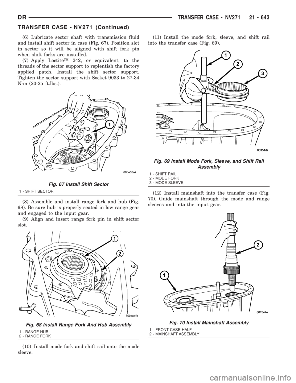
(6) Lubricate sector shaft with transmission fluid
and install shift sector in case (Fig. 67). Position slot
in sector so it will be aligned with shift fork pin
when shift forks are installed.
(7) Apply LoctiteŸ 242, or equivalent, to the
threads of the sector support to replentish the factory
applied patch. Install the shift sector support.
Tighten the sector support with Socket 9033 to 27-34
N´m (20-25 ft.lbs.).
(8) Assemble and install range fork and hub (Fig.
68). Be sure hub is properly seated in low range gear
and engaged to the input gear.
(9) Align and insert range fork pin in shift sector
slot.
(10) Install mode fork and shift rail onto the mode
sleeve.(11) Install the mode fork, sleeve, and shift rail
into the transfer case (Fig. 69).
(12) Install mainshaft into the transfer case (Fig.
70). Guide mainshaft through the mode and range
sleeves and into the input gear.
Fig. 67 Install Shift Sector
1 - SHIFT SECTOR
Fig. 68 Install Range Fork And Hub Assembly
1 - RANGE HUB
2 - RANGE FORK
Fig. 69 Install Mode Fork, Sleeve, and Shift Rail
Assembly
1 - SHIFT RAIL
2 - MODE FORK
3 - MODE SLEEVE
Fig. 70 Install Mainshaft Assembly
1 - FRONT CASE HALF
2 - MAINSHAFT ASSEMBLY
DRTRANSFER CASE - NV271 21 - 643
TRANSFER CASE - NV271 (Continued)
Page 2498 of 2895
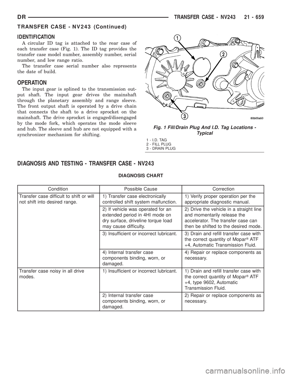
IDENTIFICATION
A circular ID tag is attached to the rear case of
each transfer case (Fig. 1). The ID tag provides the
transfer case model number, assembly number, serial
number, and low range ratio.
The transfer case serial number also represents
the date of build.
OPERATION
The input gear is splined to the transmission out-
put shaft. The input gear drives the mainshaft
through the planetary assembly and range sleeve.
The front output shaft is operated by a drive chain
that connects the shaft to a drive sprocket on the
mainshaft. The drive sprocket is engaged/disengaged
by the mode fork, which operates the mode sleeve
and hub. The sleeve and hub are not equipped with a
synchronizer mechanism for shifting.
DIAGNOSIS AND TESTING - TRANSFER CASE - NV243
DIAGNOSIS CHART
Condition Possible Cause Correction
Transfer case difficult to shift or will
not shift into desired range.1) Transfer case electronically
controlled shift system malfunction.1) Verify proper operation per the
appropriate diagnostic manual.
2) If vehicle was operated for an
extended period in 4HI mode on
dry surface, driveline torque load
may cause difficulty.2) Drive the vehicle in a straight line
and momentarily release the
accelerator. The transfer case can
then be shifted to the desired mode.
3) Insufficient or incorrect lubricant. 3) Drain and refill transfer case with
the correct quantity of MoparTAT F
+4, Automatic Transmission Fluid.
4) Internal transfer case
components binding, worn, or
damaged.4) Repair or replace components as
necessary.
Transfer case noisy in all drive
modes.1) Insufficient or incorrect lubricant. 1) Drain and refill transfer case with
the correct quantity of MoparTAT F
+4, type 9602, Automatic
Transmission Fluid.
2) Internal transfer case
components binding, worn, or
damaged.2) Repair or replace components as
necessary.
Fig. 1 Fill/Drain Plug And I.D. Tag Locations -
Typical
1 - I.D. TAG
2 - FILL PLUG
3 - DRAIN PLUG
DRTRANSFER CASE - NV243 21 - 659
TRANSFER CASE - NV243 (Continued)
Page 2504 of 2895
(5) Pull mainshaft assembly out of input gear,
mode sleeve, and case (Fig. 20).
(6) Remove mode fork, mode sleeve, and shift rail
as assembly (Fig. 21). Note which way the sleeve fits
in the fork (long side of sleeve goes to front).
(7) Remove range fork retaining ring.
(8) Remove range fork and hub as an assembly
(Fig. 22). Note fork position for installation reference.
(9) Remove shift sector (Fig. 23).
(10) Remove the shift sector o-ring (Fig. 24).
Fig. 20 Remove Mainshaft
1 - FRONT CASE
2 - MAINSHAFT
Fig. 21 Mode Fork And Sleeve Removal
1 - MODE SLEEVE
2 - MODE FORK AND RAIL
Fig. 22 Range Fork And Hub Removal
1 - RANGE HUB
2 - RANGE FORK
Fig. 23 Shift Sector Removal
1 - SHIFT SECTOR
Fig. 24 Remove the Shift Sector O-Ring
1 - TRANSFER CASE FRONT HOUSING
2 - SHIFT SECTOR O-RING
DRTRANSFER CASE - NV243 21 - 665
TRANSFER CASE - NV243 (Continued)