2003 DODGE RAM Front hub assembly
[x] Cancel search: Front hub assemblyPage 1896 of 2895
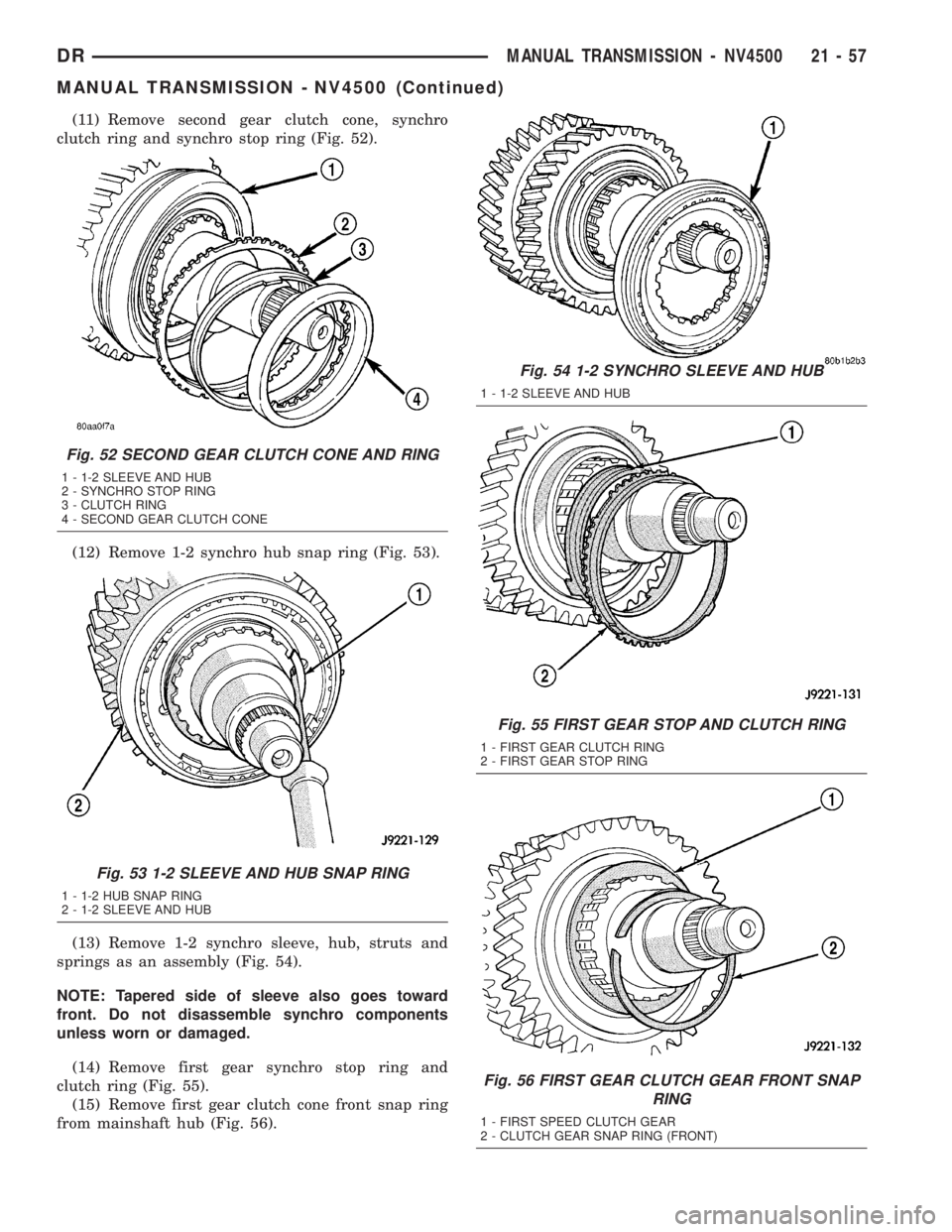
(11) Remove second gear clutch cone, synchro
clutch ring and synchro stop ring (Fig. 52).
(12) Remove 1-2 synchro hub snap ring (Fig. 53).
(13) Remove 1-2 synchro sleeve, hub, struts and
springs as an assembly (Fig. 54).
NOTE: Tapered side of sleeve also goes toward
front. Do not disassemble synchro components
unless worn or damaged.
(14) Remove first gear synchro stop ring and
clutch ring (Fig. 55).
(15) Remove first gear clutch cone front snap ring
from mainshaft hub (Fig. 56).
Fig. 52 SECOND GEAR CLUTCH CONE AND RING
1 - 1-2 SLEEVE AND HUB
2 - SYNCHRO STOP RING
3 - CLUTCH RING
4 - SECOND GEAR CLUTCH CONE
Fig. 53 1-2 SLEEVE AND HUB SNAP RING
1 - 1-2 HUB SNAP RING
2 - 1-2 SLEEVE AND HUB
Fig. 54 1-2 SYNCHRO SLEEVE AND HUB
1 - 1-2 SLEEVE AND HUB
Fig. 55 FIRST GEAR STOP AND CLUTCH RING
1 - FIRST GEAR CLUTCH RING
2 - FIRST GEAR STOP RING
Fig. 56 FIRST GEAR CLUTCH GEAR FRONT SNAP
RING
1 - FIRST SPEED CLUTCH GEAR
2 - CLUTCH GEAR SNAP RING (FRONT)
DRMANUAL TRANSMISSION - NV4500 21 - 57
MANUAL TRANSMISSION - NV4500 (Continued)
Page 1903 of 2895
(6) Install countershaft rear bearing plate (Fig.
74).
NOTE: Verify plate is seated in reverse idler shaft
notch and end play shims are still in position
before installing bolts.
(7) Apply 1-2 drops Mopar Loc N' Seal or equiva-
lent to threads of rear bearing plate bolts. Then
install and tighten bearing plate bolts to 23 N´m (200
in. lbs.).
SHIFT LUG AND RAIL
(1) Lubricate shift lug and rail with CastroltSyn-
torq or equivalent.
(2) Insert shift lug rail part way into case.
(3) Install shift lug on rail.
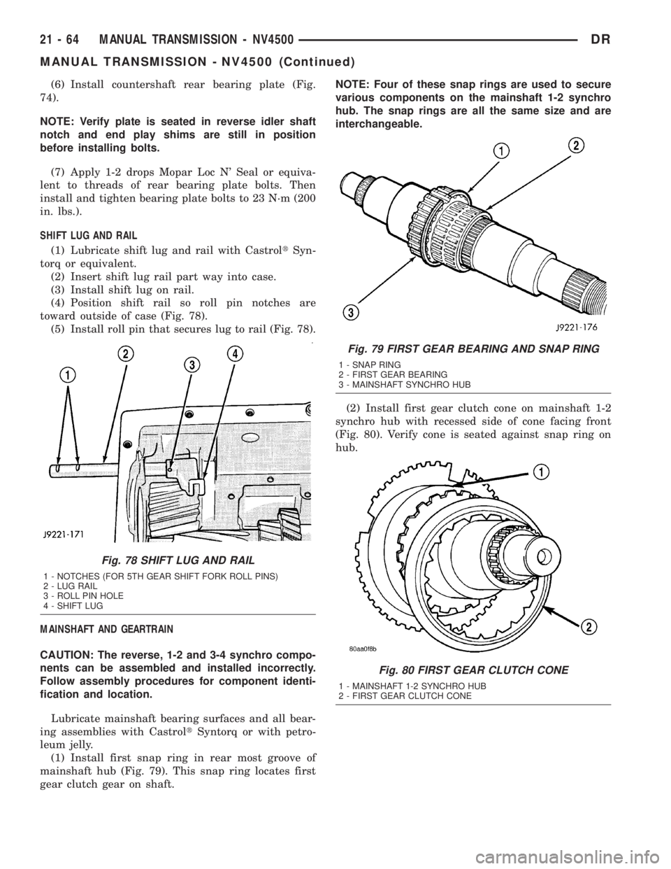
(4) Position shift rail so roll pin notches are
toward outside of case (Fig. 78).
(5) Install roll pin that secures lug to rail (Fig. 78).
MAINSHAFT AND GEARTRAIN
CAUTION: The reverse, 1-2 and 3-4 synchro compo-
nents can be assembled and installed incorrectly.
Follow assembly procedures for component identi-
fication and location.
Lubricate mainshaft bearing surfaces and all bear-
ing assemblies with CastroltSyntorq or with petro-
leum jelly.
(1) Install first snap ring in rear most groove of
mainshaft hub (Fig. 79). This snap ring locates first
gear clutch gear on shaft.NOTE: Four of these snap rings are used to secure
various components on the mainshaft 1-2 synchro
hub. The snap rings are all the same size and are
interchangeable.
(2) Install first gear clutch cone on mainshaft 1-2
synchro hub with recessed side of cone facing front
(Fig. 80). Verify cone is seated against snap ring on
hub.
Fig. 78 SHIFT LUG AND RAIL
1 - NOTCHES (FOR 5TH GEAR SHIFT FORK ROLL PINS)
2 - LUG RAIL
3 - ROLL PIN HOLE
4 - SHIFT LUG
Fig. 79 FIRST GEAR BEARING AND SNAP RING
1 - SNAP RING
2 - FIRST GEAR BEARING
3 - MAINSHAFT SYNCHRO HUB
Fig. 80 FIRST GEAR CLUTCH CONE
1 - MAINSHAFT 1-2 SYNCHRO HUB
2 - FIRST GEAR CLUTCH CONE
21 - 64 MANUAL TRANSMISSION - NV4500DR
MANUAL TRANSMISSION - NV4500 (Continued)
Page 1908 of 2895
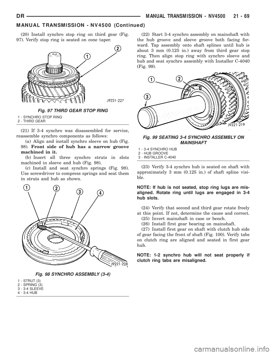
(20) Install synchro stop ring on third gear (Fig.
97). Verify stop ring is seated on cone taper.
(21) If 3-4 synchro was disassembled for service,
reassemble synchro components as follows:
(a) Align and install synchro sleeve on hub (Fig.
98).Front side of hub has a narrow groove
machined in it.
(b) Insert all three synchro struts in slots
machined in sleeve and hub (Fig. 98).
(c) Install and seat synchro springs (Fig. 98).
Use screwdriver to compress springs and seat them
in struts and hub as shown.(22) Start 3-4 synchro assembly on mainshaft with
the hub groove and sleeve groove both facing for-
ward. Tap assembly onto shaft splines until hub is
about 3 mm (0.125 in.) away from third gear stop
ring. Then align stop ring with synchro sleeve and
hub and seat synchro assembly with Installer C-4040
(Fig. 99).
(23) Verify 3-4 synchro hub is seated on shaft with
approximately 3 mm (0.125 in.) of shaft spline visi-
ble.
NOTE: If hub is not seated, stop ring lugs are mis-
aligned. Rotate ring until lugs are engaged in 3-4
hub slots.
(24) Verify that second and third gear rotate freely
at this point. If not, determine the cause and correct.
(25) Invert mainshaft in case or bench.
(26) Install first gear bearing on mainshaft.
(27) Install first gear on shaft with clutch hub side
of gear facing the front of shaft (Fig. 100). Verify tabs
on clutch ring are aligned and seated in first gear
hub.
NOTE: 1-2 synchro hub will not seat properly if
clutch ring tabs are misaligned.
Fig. 97 THIRD GEAR STOP RING
1 - SYNCHRO STOP RING
2 - THIRD GEAR
Fig. 98 SYNCHRO ASSEMBLY (3-4)
1 - STRUT (3)
2 - SPRING (3)
3 - 3-4 SLEEVE
4 - 3-4 HUB
Fig. 99 SEATING 3-4 SYNCHRO ASSEMBLY ON
MAINSHAFT
1 - 3-4 SYNCHRO HUB
2 - HUB GROOVE
3 - INSTALLER C-4040
DRMANUAL TRANSMISSION - NV4500 21 - 69
MANUAL TRANSMISSION - NV4500 (Continued)
Page 1910 of 2895

(e) Install second and third struts in same man-
ner as described in step (d).
(f) Work sleeve upward on hub until struts are
centered and seated in sleeve. Sleeve should be in
neutral position after seating struts.
(34) Install reverse gear and synchro assembly on
mainshaft (Fig. 104). Rotate assembly until stop ring
lugs engage in hub slots and gear drops into seated
position.
(35) Install reverse gear thrust washer (Fig. 105).
(36) Install rear bearing on mainshaft with
Installer 6446. Seat bearing on output shaft and
against thrust washer (Fig. 106).
(37) Install fourth gear stop ring in 3-4 synchro
sleeve (Fig. 107).
(38) Install fourth gear clutch gear in stop ring
(Fig. 108).
(39) Roll gear case onto its left side.
(40) Grip mainshaft at pilot bearing hub and just
behind reverse gear. Then lift assembly and guide
rear of shaft through bearing bore at rear of case.
(41) Continue holding front of shaft but switch
grip at rear to shaft output splines. Lift mainshaft
assembly slightly, align gears and seat assembly in
case.
Fig. 104 REVERSE GEAR
1 - REVERSE GEAR AND SYNCHRO ASSEMBLY
Fig. 105 REVERSE GEAR THRUST WASHER
1 - THRUST WASHER
2 - REVERSE GEAR
Fig. 106 MAINSHAFT REAR BEARING
1 - INSTALLER
2 - MAINSHAFT REAR BEARING
Fig. 107 FOURTH GEAR STOP RING
1 - 3-4 SYNCHRO SLEEVE
2 - FOURTH SPEED STOP RING
Fig. 108 FOURTH GEAR CLUTCH GEAR
1 - FOURTH SPEED CLUTCH GEAR
DRMANUAL TRANSMISSION - NV4500 21 - 71
MANUAL TRANSMISSION - NV4500 (Continued)
Page 2001 of 2895
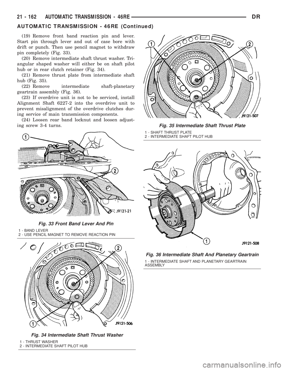
(19) Remove front band reaction pin and lever.
Start pin through lever and out of case bore with
drift or punch. Then use pencil magnet to withdraw
pin completely (Fig. 33).
(20) Remove intermediate shaft thrust washer. Tri-
angular shaped washer will either be on shaft pilot
hub or in rear clutch retainer (Fig. 34).
(21) Remove thrust plate from intermediate shaft
hub (Fig. 35).
(22) Remove intermediate shaft-planetary
geartrain assembly (Fig. 36).
(23) If overdrive unit is not to be serviced, install
Alignment Shaft 6227-2 into the overdrive unit to
prevent misalignment of the overdrive clutches dur-
ing service of main transmission components.
(24) Loosen rear band locknut and loosen adjust-
ing screw 3-4 turns.
Fig. 33 Front Band Lever And Pin
1 - BAND LEVER
2 - USE PENCIL MAGNET TO REMOVE REACTION PIN
Fig. 34 Intermediate Shaft Thrust Washer
1 - THRUST WASHER
2 - INTERMEDIATE SHAFT PILOT HUB
Fig. 35 Intermediate Shaft Thrust Plate
1 - SHAFT THRUST PLATE
2 - INTERMEDIATE SHAFT PILOT HUB
Fig. 36 Intermediate Shaft And Planetary Geartrain
1 - INTERMEDIATE SHAFT AND PLANETARY GEARTRAIN
ASSEMBLY
21 - 162 AUTOMATIC TRANSMISSION - 46REDR
AUTOMATIC TRANSMISSION - 46RE (Continued)
Page 2007 of 2895
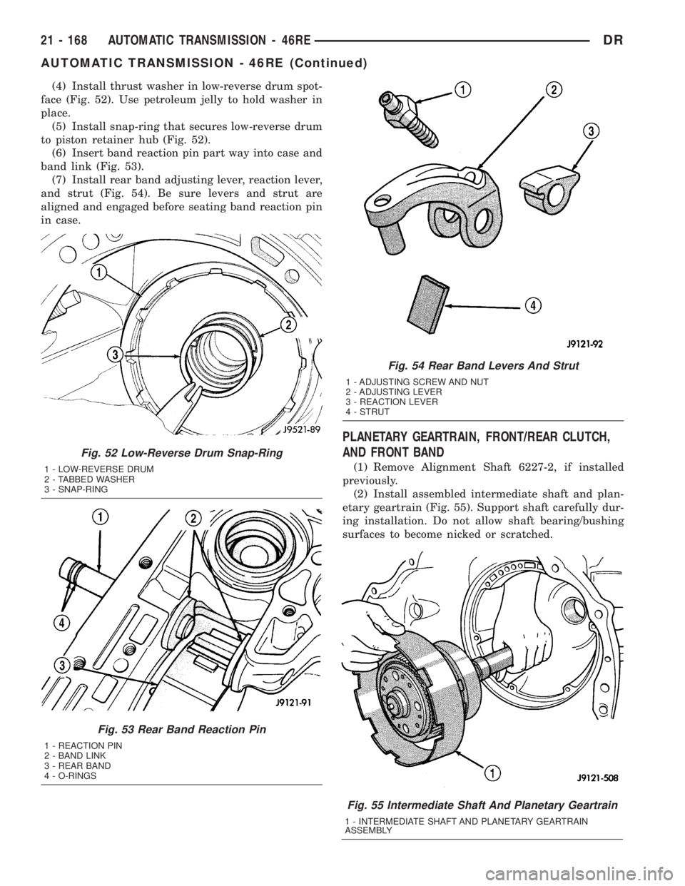
(4) Install thrust washer in low-reverse drum spot-
face (Fig. 52). Use petroleum jelly to hold washer in
place.
(5) Install snap-ring that secures low-reverse drum
to piston retainer hub (Fig. 52).
(6) Insert band reaction pin part way into case and
band link (Fig. 53).
(7) Install rear band adjusting lever, reaction lever,
and strut (Fig. 54). Be sure levers and strut are
aligned and engaged before seating band reaction pin
in case.
PLANETARY GEARTRAIN, FRONT/REAR CLUTCH,
AND FRONT BAND
(1) Remove Alignment Shaft 6227-2, if installed
previously.
(2) Install assembled intermediate shaft and plan-
etary geartrain (Fig. 55). Support shaft carefully dur-
ing installation. Do not allow shaft bearing/bushing
surfaces to become nicked or scratched.
Fig. 55 Intermediate Shaft And Planetary Geartrain
1 - INTERMEDIATE SHAFT AND PLANETARY GEARTRAIN
ASSEMBLY
Fig. 52 Low-Reverse Drum Snap-Ring
1 - LOW-REVERSE DRUM
2 - TABBED WASHER
3 - SNAP-RING
Fig. 53 Rear Band Reaction Pin
1 - REACTION PIN
2 - BAND LINK
3 - REAR BAND
4 - O-RINGS
Fig. 54 Rear Band Levers And Strut
1 - ADJUSTING SCREW AND NUT
2 - ADJUSTING LEVER
3 - REACTION LEVER
4 - STRUT
21 - 168 AUTOMATIC TRANSMISSION - 46REDR
AUTOMATIC TRANSMISSION - 46RE (Continued)
Page 2008 of 2895
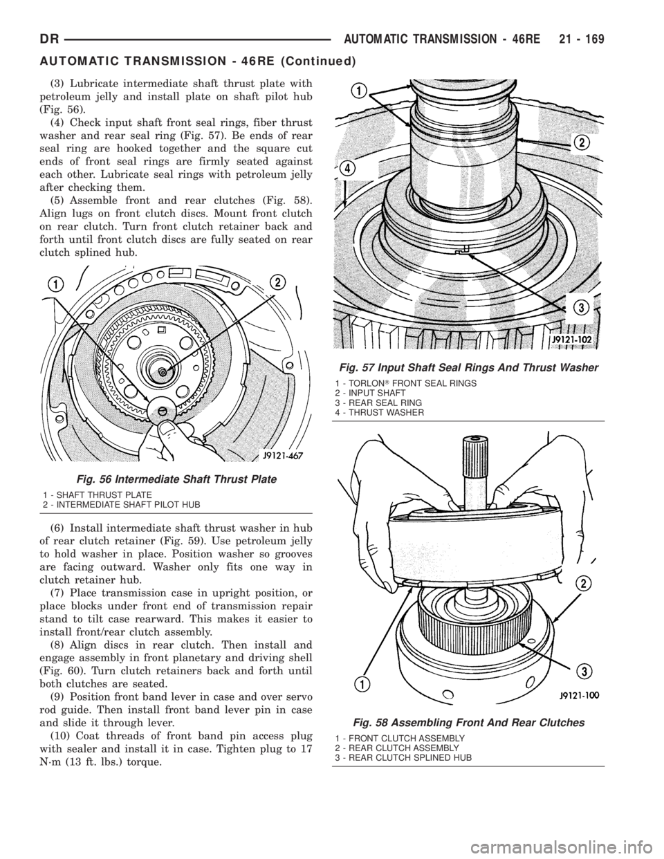
(3) Lubricate intermediate shaft thrust plate with
petroleum jelly and install plate on shaft pilot hub
(Fig. 56).
(4) Check input shaft front seal rings, fiber thrust
washer and rear seal ring (Fig. 57). Be ends of rear
seal ring are hooked together and the square cut
ends of front seal rings are firmly seated against
each other. Lubricate seal rings with petroleum jelly
after checking them.
(5) Assemble front and rear clutches (Fig. 58).
Align lugs on front clutch discs. Mount front clutch
on rear clutch. Turn front clutch retainer back and
forth until front clutch discs are fully seated on rear
clutch splined hub.
(6) Install intermediate shaft thrust washer in hub
of rear clutch retainer (Fig. 59). Use petroleum jelly
to hold washer in place. Position washer so grooves
are facing outward. Washer only fits one way in
clutch retainer hub.
(7) Place transmission case in upright position, or
place blocks under front end of transmission repair
stand to tilt case rearward. This makes it easier to
install front/rear clutch assembly.
(8) Align discs in rear clutch. Then install and
engage assembly in front planetary and driving shell
(Fig. 60). Turn clutch retainers back and forth until
both clutches are seated.
(9) Position front band lever in case and over servo
rod guide. Then install front band lever pin in case
and slide it through lever.
(10) Coat threads of front band pin access plug
with sealer and install it in case. Tighten plug to 17
N´m (13 ft. lbs.) torque.
Fig. 56 Intermediate Shaft Thrust Plate
1 - SHAFT THRUST PLATE
2 - INTERMEDIATE SHAFT PILOT HUB
Fig. 57 Input Shaft Seal Rings And Thrust Washer
1 - TORLONTFRONT SEAL RINGS
2 - INPUT SHAFT
3 - REAR SEAL RING
4 - THRUST WASHER
Fig. 58 Assembling Front And Rear Clutches
1 - FRONT CLUTCH ASSEMBLY
2 - REAR CLUTCH ASSEMBLY
3 - REAR CLUTCH SPLINED HUB
DRAUTOMATIC TRANSMISSION - 46RE 21 - 169
AUTOMATIC TRANSMISSION - 46RE (Continued)
Page 2009 of 2895
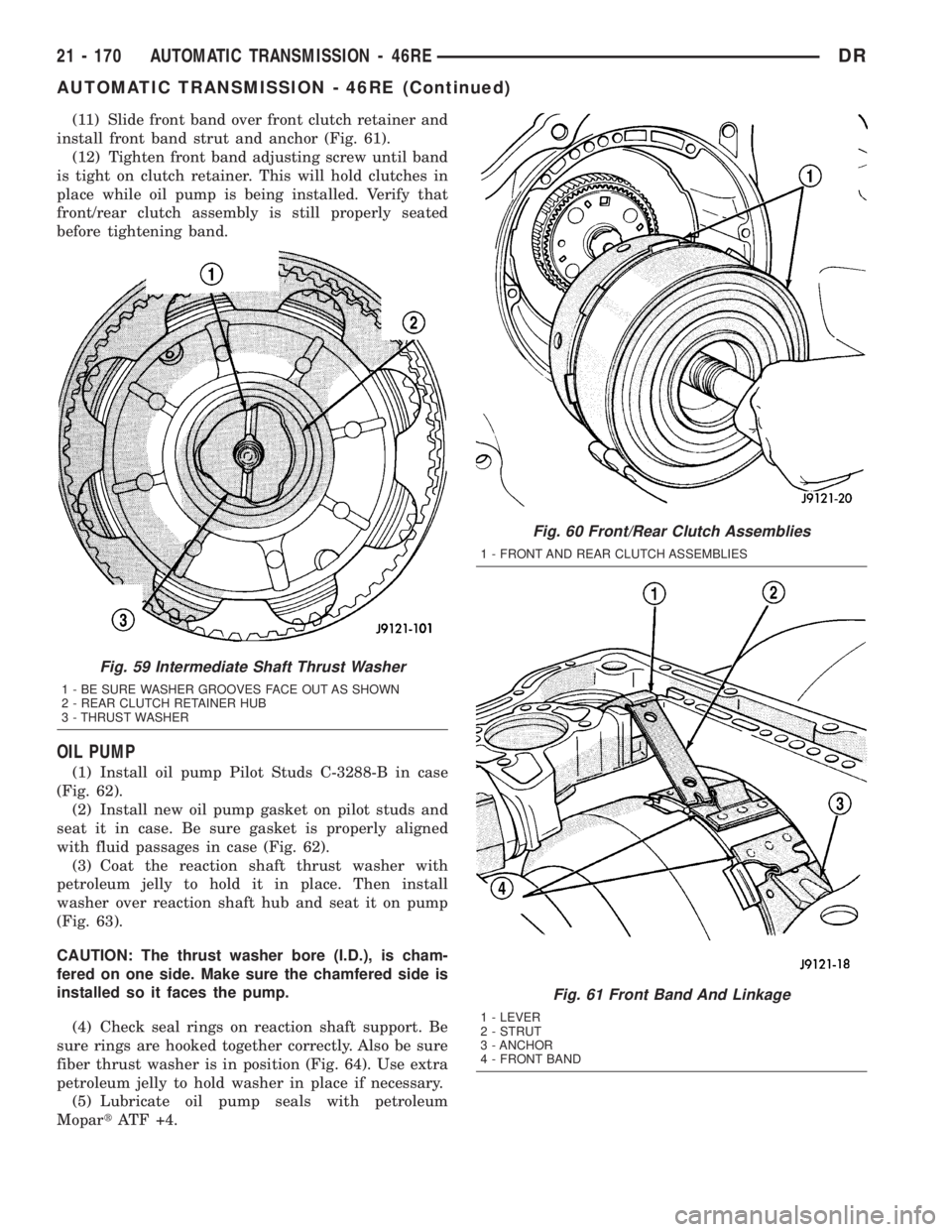
(11) Slide front band over front clutch retainer and
install front band strut and anchor (Fig. 61).
(12) Tighten front band adjusting screw until band
is tight on clutch retainer. This will hold clutches in
place while oil pump is being installed. Verify that
front/rear clutch assembly is still properly seated
before tightening band.
OIL PUMP
(1) Install oil pump Pilot Studs C-3288-B in case
(Fig. 62).
(2) Install new oil pump gasket on pilot studs and
seat it in case. Be sure gasket is properly aligned
with fluid passages in case (Fig. 62).
(3) Coat the reaction shaft thrust washer with
petroleum jelly to hold it in place. Then install
washer over reaction shaft hub and seat it on pump
(Fig. 63).
CAUTION: The thrust washer bore (I.D.), is cham-
fered on one side. Make sure the chamfered side is
installed so it faces the pump.
(4) Check seal rings on reaction shaft support. Be
sure rings are hooked together correctly. Also be sure
fiber thrust washer is in position (Fig. 64). Use extra
petroleum jelly to hold washer in place if necessary.
(5) Lubricate oil pump seals with petroleum
MopartATF +4.
Fig. 59 Intermediate Shaft Thrust Washer
1 - BE SURE WASHER GROOVES FACE OUT AS SHOWN
2 - REAR CLUTCH RETAINER HUB
3 - THRUST WASHER
Fig. 60 Front/Rear Clutch Assemblies
1 - FRONT AND REAR CLUTCH ASSEMBLIES
Fig. 61 Front Band And Linkage
1 - LEVER
2 - STRUT
3 - ANCHOR
4 - FRONT BAND
21 - 170 AUTOMATIC TRANSMISSION - 46REDR
AUTOMATIC TRANSMISSION - 46RE (Continued)