2003 DODGE RAM Front hub assembly
[x] Cancel search: Front hub assemblyPage 91 of 2895

FRONT AXLE - C205F
TABLE OF CONTENTS
page page
FRONT AXLE - C205F
DESCRIPTION.........................18
OPERATION...........................18
DIAGNOSIS AND TESTING................18
REMOVAL.............................21
INSTALLATION.........................21
ADJUSTMENTS........................21
SPECIFICATIONS.......................29
SPECIAL TOOLS.......................30
AXLE SHAFTS
REMOVAL.............................33
INSTALLATION.........................33
AXLE SHAFT SEALS
REMOVAL.............................33
INSTALLATION.........................33
AXLE BEARINGS
REMOVAL.............................33INSTALLATION.........................34
PINION SEAL
REMOVAL.............................34
INSTALLATION.........................35
DIFFERENTIAL
DESCRIPTION.........................36
OPERATION...........................36
REMOVAL.............................36
DISASSEMBLY.........................37
ASSEMBLY............................38
INSTALLATION.........................38
DIFFERENTIAL CASE BEARINGS
REMOVAL.............................39
INSTALLATION.........................39
PINION GEAR/RING GEAR
REMOVAL.............................40
INSTALLATION.........................42
FRONT AXLE - C205F
DESCRIPTION
The axle consists of an alumunum center section
with an axle tube extending from one side. The tube
is pressed into the differential housing. The power is
transferred from the axle through two constant veloc-
ity (C/V) drive shafts to the wheel hubs. The drive
shafts are identical and interchangeable.
OPERATION
The axle receives power from the propeller shaft.
The propeller shaft is connected to the pinion gear
which rotates the differential through the gear mesh
with the ring gear bolted to the differential case. The
engine power is transmitted to the axle shafts
through the pinion mate and side gears. The side
gears are splined to the axle shafts.
DIAGNOSIS AND TESTING
GEAR NOISE
Axle gear noise can be caused by insufficient lubri-
cant, incorrect backlash, tooth contact, worn/damaged
gears or the carrier housing not having the proper
offset and squareness.
Gear noise usually happens at a specific speed
range. The noise can also occur during a specific type
of driving condition. These conditions are accelera-
tion, deceleration, coast, or constant load.When road testing, first warm-up the axle fluid by
driving the vehicle at least 5 miles and then acceler-
ate the vehicle to the speed range where the noise is
the greatest. Shift out-of-gear and coast through the
peak-noise range. If the noise stops or changes
greatly:
²Check for insufficient lubricant.
²Incorrect ring gear backlash.
²Gear damage.
Differential side gears and pinions can be checked
by turning the vehicle. They usually do not cause
noise during straight-ahead driving when the gears
are unloaded. The side gears are loaded during vehi-
cle turns. A worn pinion mate shaft can also cause a
snapping or a knocking noise.
BEARING NOISE
The axle shaft, differential and pinion bearings can
all produce noise when worn or damaged. Bearing
noise can be either a whining, or a growling sound.
Pinion bearings have a constant-pitch noise. This
noise changes only with vehicle speed. Pinion bearing
noise will be higher pitched because it rotates at a
faster rate. Drive the vehicle and load the differen-
tial. If bearing noise occurs, the rear pinion bearing
is the source of the noise. If the bearing noise is
heard during a coast, the front pinion bearing is the
source.
Worn or damaged differential bearings usually pro-
duce a low pitch noise. Differential bearing noise is
similar to pinion bearing noise. The pitch of differen-
3 - 18 FRONT AXLE - C205FDR
Page 118 of 2895

FRONT AXLE - 9 1/4 AA
TABLE OF CONTENTS
page page
FRONT AXLE - 9 1/4 AA
DESCRIPTION.........................45
OPERATION...........................45
DIAGNOSIS AND TESTING................45
REMOVAL.............................48
INSTALLATION.........................48
ADJUSTMENTS........................49
SPECIFICATIONS.......................53
SPECIAL TOOLS.......................53
AXLE SHAFTS
REMOVAL.............................56
DISASSEMBLY.........................56
ASSEMBLY............................58
INSTALLATION.........................58
AXLE SHAFT SEALS
REMOVAL.............................58
INSTALLATION.........................58PINION SEAL
REMOVAL.............................60
INSTALLATION.........................60
DIFFERENTIAL
DESCRIPTION.........................61
OPERATION...........................61
REMOVAL.............................61
DISASSEMBLY.........................62
ASSEMBLY............................63
INSTALLATION.........................63
DIFFERENTIAL CASE BEARINGS
REMOVAL.............................64
INSTALLATION.........................65
PINION GEAR/RING GEAR
REMOVAL.............................65
INSTALLATION.........................66
FRONT AXLE - 9 1/4 AA
DESCRIPTION
The axle consists of a cast iron center casting dif-
ferential housing with axle shaft tubes extending
from each side. The tubes are pressed into the differ-
ential housing and welded. The design has the cen-
terline of the pinion set above the centerline of the
ring gear. The axle has full-floating axle shafts,
meaning the shaft are supported by the hub bear-
ings. The axle has a vent used to relieve internal
pressure caused by lubricant vaporization and inter-
nal expansion.
OPERATION
The axle receives power from the front propeller
shaft. The propeller shaft is connected to the pinion
gear which rotates the differential through the gear
mesh with the ring gear bolted to the differential
case. The engine power is transmitted to the axle
shafts through the pinion mate and side gears. The
side gears are splined to the axle shafts.
DIAGNOSIS AND TESTING
GEAR NOISE
Axle gear noise can be caused by insufficient lubri-
cant, incorrect backlash, tooth contact, worn/damaged
gears or the carrier housing not having the proper
offset and squareness.Gear noise usually happens at a specific speed
range. The noise can also occur during a specific type
of driving condition. These conditions are accelera-
tion, deceleration, coast, or constant load.
When road testing, first warm-up the axle fluid by
driving the vehicle at least 5 miles and then acceler-
ate the vehicle to the speed range where the noise is
the greatest. Shift out-of-gear and coast through the
peak-noise range. If the noise stops or changes
greatly:
²Check for insufficient lubricant.
²Incorrect ring gear backlash.
²Gear damage.
Differential side gears and pinions can be checked
by turning the vehicle. They usually do not cause
noise during straight-ahead driving when the gears
are unloaded. The side gears are loaded during vehi-
cle turns. A worn pinion mate shaft can also cause a
snapping or a knocking noise.
BEARING NOISE
The axle shaft, differential and pinion bearings can
all produce noise when worn or damaged. Bearing
noise can be either a whining, or a growling sound.
Pinion bearings have a constant-pitch noise. This
noise changes only with vehicle speed. Pinion bearing
noise will be higher pitched because it rotates at a
faster rate. Drive the vehicle and load the differen-
tial. If bearing noise occurs, the rear pinion bearing
is the source of the noise. If the bearing noise is
DRFRONT AXLE - 9 1/4 AA 3 - 45
Page 129 of 2895

AXLE SHAFTS
REMOVAL
(1) Remove wheel and tire assembly.
(2) Remove brake caliper, rotor and ABS wheel
speed sensor if equipped.
(3) Remove axle shaft cotter pin, hub nut and
washer (Fig. 14).
(4) Remove the four hub bearing bolts (Fig. 15)
from the back of the steering knuckle.
(5) Remove hub bearing from the steering knuckle.
(6) Remove axle shaft (Fig. 16) from steering
knuckle and axle housing.
DISASSEMBLY
Single cardan U-joint components are not service-
able. If defective they must be replaced as a unit.
CAUTION: Clamp only the narrow forged portion of
the yoke in the vise. To avoid distorting the yoke,
do not over tighten the vise jaws.
(1) Remove the bearing cap retaining snap rings
(Fig. 17).
NOTE: Saturate the bearing caps with penetrating
oil prior to removal.
(2) Locate a socket with an inside diameter that is
larger than the bearing cap. Place the socket (receiv-
er) against the yoke and around the perimeter of the
bearing cap to be removed.
ADAPTERS 8879
ADJUSTER WRENCH 8883
FLANGE WRENCH 8979
FLANGE PULLER 8992
Fig. 14 AXLE NUT
1 - AXLE NUT
2 - AXLE
3 - COTTER PIN
3 - 56 FRONT AXLE - 9 1/4 AADR
FRONT AXLE - 9 1/4 AA (Continued)
Page 131 of 2895

ASSEMBLY
(1) Pack the bearing caps 1/3 full of wheel bearing
lubricant. Apply extreme pressure (EP), lithium-base
lubricant to aid in installation.
(2) Position the spider in the yoke. Insert the seals
and bearings. Tap the bearing caps into the yoke
bores far enough to hold the spider in position.
(3) Place the socket (driver) against one bearing
cap. Position the yoke with the socket in a vise.
(4) Tighten the vise to force the bearing caps into
the yoke. Force the caps enough to install the retain-
ing clips.
(5) Install the bearing cap retaining clips.
(6) Install axle shaft.
INSTALLATION
(1) Clean axle shaft and apply a thin film of
Mopar Wheel Bearing Grease to the shaft splines
and hub bore.
(2) Install axle shaft through the steering knuckle
and into the differential side gears (Fig. 19).
CAUTION: Do not damage axle shaft seal during
axle installtion.
(3) Install hub bearing in the knuckle.
(4) Install hub bearing bolts and tighten to 202
N´m (149 ft. lbs.).
(5) Install ABS wheel speed sensor, brake rotor
and caliper.
(6) Install axle washer and nut. Tighten axle nut
to 179 N´m (132 ft. lbs.).(7) Rotate axle several 5 to 10 times to seat the
wheel bearing.
(8) Tighten axle nut to final torque of 356 N´m
(263 ft. lbs.).
(9) Align nut to next cotter pin hole and install
new cotter pin.
(10) Install wheel and tire assembly.
AXLE SHAFT SEALS
REMOVAL
(1) Remove hub bearings and axle shafts.
(2) Remove differential from differential housing.
(3) Remove differential bearing adjusters (Fig. 20).
(4) Remove axle seals (Fig. 21) located behind
adjusters with Receiver 8498 and Extractor 6310.
(5) Install Receiver 8498 into the adjuster bore.
(6) Install Extractor Rod 6310 with Extractor Foot
6310-9 through the receiver and the axle seal (Fig.
22).
(7) Install Extractor Plate 6310-2 and Nut 6310-7
on the extractor rod.
(8) Tighten nut on the extractor rod (Fig. 23) and
pull the seal out and into the receiver.
INSTALLATION
(1) Install axle seal on Installer Cups 8885-2 and
position cups with seals into the housing.
NOTE: Seal are installed with the axle guide facing
outward.
Fig. 19 AXLE SHAFT
1 - AXLE YOKE
2 - AXLE SHAFT
3 - KNUCKLE
Fig. 20 ADJUSTERS
1 - DIFFERENTIAL CASE BEARING ADJUSTERS
2 - DIFFERENTIAL HOUSING
3 - 58 FRONT AXLE - 9 1/4 AADR
AXLE SHAFTS (Continued)
Page 234 of 2895

DESCRIPTION N´m Ft. Lbs. In. Lbs.
Support Plate
Mounting Bolts/Nuts64 47 Ð
Brake Line Fittings
Master Cylinder19 14 170
Brake Line Fittings
Junction Block19 14 170
Caliper
Brake Line Banjo Bolt27 20 245
Brake Hose
Front Bolts To Frame10 7.5 Ð
Brake Hose
Front Fitting19 14 250
Brake Hose
Rear Fitting19 14 250
Parking Brake Pedal Assembly 19 14 250
Hub/Bearing
Bolts163 120 Ð
BASE BRAKE
SPECIFICATIONS
DESCRIPTION SPECIFICATION
Front Disc Brake Caliper
TypeDual Piston Sliding
Rear Disc Brake Caliper
TypeSingle Piston Sliding
Front Disc Brake Caliper 54 mm (2.00 in.)
Front Disc Brake Rotor 336ý28 mm (13.2ý1.1
in.)
Front/Rear Disc Brake
Rotor
Max. Runout0.127 mm (0.005 in.)
Front/Rear Disc Brake
Rotor
Max. Thickness Variation0.025 mm (0.001 in.)
Minimum Front Rotor
Thickness26.4 mm (1.039 in.)
Mininium Rear Rotor
Thickness28.39 mm (1.117 in)
Rear Disc Brake Caliper 1x54 mm (2.12 in)
Rear Disc Brake Rotor 350x22 mm (.86 in)
Brake Booster
Type
Gasoline EnginesVacuum Dual Diaphragm
BRAKE LINES
STANDARD PROCEDURE
STANDARD PROCEDURE - DOUBLE INVERTED
FLARING
A preformed metal brake tube is recommended and
preferred for all repairs. However, double-wall steel
tube can be used for emergency repair when factory
replacement parts are not readily available.
(1) Cut off damaged tube with Tubing Cutter.
(2) Ream cut edges of tubing to ensure proper
flare.
(3) Install replacement tube nut on the tube.
(4) Insert tube in flaring tool.
(5) Place gauge form over the end of the tube.
(6) Push tubing through flaring tool jaws until
tube contacts recessed notch in gauge that matches
tube diameter.
(7) Tighten the tool bar on the tube
(8) Insert plug on gauge in the tube. Then swing
compression disc over gauge and center tapered flar-
ing screw in recess of compression disc (Fig. 3).
(9) Tighten tool handle until plug gauge is
squarely seated on jaws of flaring tool. This will start
the inverted flare.
(10) Remove the plug gauge and complete the
inverted flare.
STANDARD PROCEDURE - ISO FLARING
A preformed metal brake tube is recommended and
preferred for all repairs. However, double-wall steel
DRBRAKES - BASE 5 - 7
HYDRAULIC/MECHANICAL (Continued)
Page 255 of 2895

(7) Install the hydraulic booster pressure lines to
the bracket and booster.
(8) Tighten the pressure lines to 41 N´m (30 ft.
lbs.).
NOTE: Inspect o-rings on the pressure line fittings
to insure they are in good condition before installa-
tion. Replace o-rings if necessary.
(9) Install the return hose to the booster.
(10) Bleed base brake system, (Refer to 5 -
BRAKES/HYDRAULIC/MECHANICAL - STAN-
DARD PROCEDURE).
(11) Fill the power steering pump with fluid,
(Refer to 19 - STEERING/PUMP - STANDARD PRO-
CEDURE).
CAUTION: MOPAR (MS-9602) ATF+4 is to be used in
the power steering system. No other power steering
or automatic transmission fluid is to be used in the
system. Damage may result to the power steering
pump and system if any other fluid is used, and do
not overfill.
(12) Bleed the hydraulic booster (Refer to 5 -
BRAKES/HYDRAULIC/MECHANICAL/POWER
BRAKE BOOSTER - STANDARD PROCEDURE).
ROTORS
REMOVAL
REMOVAL - REAR
(1) Raise and support the vehicle
(2) Remove the tire and wheel assembly.
(3) Remove the disc brake caliper, (Refer to 5 -
BRAKES/HYDRAULIC/MECHANICAL/DISC
BRAKE CALIPERS - REMOVAL).
(4) Remove the caliper adapter bolts (Fig.
50).(Refer to 5 - BRAKES/HYDRAULIC/MECHANI-
CAL/DISC BRAKE CALIPER ADAPTER -
REMOVAL)
(5) Remove the retianing clips and rotor assembly
(Fig. 50).
REMOVAL - FRONT
(1) Raise and support the vehicle.
(2) Remove the wheel and tire assembly.
(3) Remove the caliper from the steering knuckle,
(Refer to 5 - BRAKES/HYDRAULIC/MECHANICAL/
DISC BRAKE CALIPERS - REMOVAL) and remove
caliper adapter assembly (Fig. 51).
NOTE: Do not allow brake hose to support caliper
adapter assembly.(4) Remove the rotor from the hub/bearing wheel
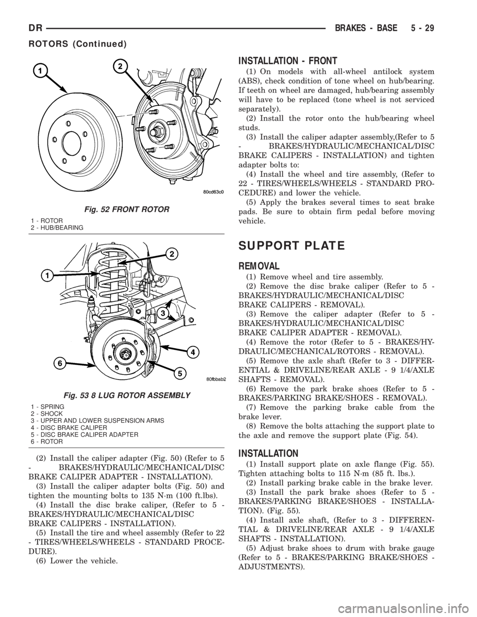
studs (Fig. 52) or (Fig. 53).
INSTALLATION
INSTALLATION - REAR
(1) Install the rotor to the axleshaft (Fig. 50).
Fig. 50 REAR ROTOR
1 - ROTOR
2 - CALIPER ADAPTER
3 - CALIPER
Fig. 51 Caliper Adapter Assembly
1 - KNUCKLE
2 - CALIPER
3 - ROTOR
5 - 28 BRAKES - BASEDR
HYDRO-BOOST BRAKE BOOSTER (Continued)
Page 256 of 2895

(2) Install the caliper adapter (Fig. 50) (Refer to 5
- BRAKES/HYDRAULIC/MECHANICAL/DISC
BRAKE CALIPER ADAPTER - INSTALLATION).
(3) Install the caliper adapter bolts (Fig. 50) and
tighten the mounting bolts to 135 N´m (100 ft.lbs).
(4) Install the disc brake caliper, (Refer to 5 -
BRAKES/HYDRAULIC/MECHANICAL/DISC
BRAKE CALIPERS - INSTALLATION).
(5) Install the tire and wheel assembly (Refer to 22
- TIRES/WHEELS/WHEELS - STANDARD PROCE-
DURE).
(6) Lower the vehicle.
INSTALLATION - FRONT
(1) On models with all-wheel antilock system
(ABS), check condition of tone wheel on hub/bearing.
If teeth on wheel are damaged, hub/bearing assembly
will have to be replaced (tone wheel is not serviced
separately).
(2) Install the rotor onto the hub/bearing wheel
studs.
(3) Install the caliper adapter assembly,(Refer to 5
- BRAKES/HYDRAULIC/MECHANICAL/DISC
BRAKE CALIPERS - INSTALLATION) and tighten
adapter bolts to:
(4) Install the wheel and tire assembly, (Refer to
22 - TIRES/WHEELS/WHEELS - STANDARD PRO-
CEDURE) and lower the vehicle.
(5) Apply the brakes several times to seat brake
pads. Be sure to obtain firm pedal before moving
vehicle.
SUPPORT PLATE
REMOVAL
(1) Remove wheel and tire assembly.
(2) Remove the disc brake caliper (Refer to 5 -
BRAKES/HYDRAULIC/MECHANICAL/DISC
BRAKE CALIPERS - REMOVAL).
(3) Remove the caliper adapter (Refer to 5 -
BRAKES/HYDRAULIC/MECHANICAL/DISC
BRAKE CALIPER ADAPTER - REMOVAL).
(4) Remove the rotor (Refer to 5 - BRAKES/HY-
DRAULIC/MECHANICAL/ROTORS - REMOVAL).
(5) Remove the axle shaft (Refer to 3 - DIFFER-
ENTIAL & DRIVELINE/REAR AXLE - 9 1/4/AXLE
SHAFTS - REMOVAL).
(6) Remove the park brake shoes (Refer to 5 -
BRAKES/PARKING BRAKE/SHOES - REMOVAL).
(7) Remove the parking brake cable from the
brake lever.
(8) Remove the bolts attaching the support plate to
the axle and remove the support plate (Fig. 54).
INSTALLATION
(1) Install support plate on axle flange (Fig. 55).
Tighten attaching bolts to 115 N´m (85 ft. lbs.).
(2) Install parking brake cable in the brake lever.
(3) Install the park brake shoes (Refer to 5 -
BRAKES/PARKING BRAKE/SHOES - INSTALLA-
TION). (Fig. 55).
(4) Install axle shaft, (Refer to 3 - DIFFEREN-
TIAL & DRIVELINE/REAR AXLE - 9 1/4/AXLE
SHAFTS - INSTALLATION).
(5) Adjust brake shoes to drum with brake gauge
(Refer to 5 - BRAKES/PARKING BRAKE/SHOES -
ADJUSTMENTS).
Fig. 52 FRONT ROTOR
1 - ROTOR
2 - HUB/BEARING
Fig. 53 8 LUG ROTOR ASSEMBLY
1 - SPRING
2 - SHOCK
3 - UPPER AND LOWER SUSPENSION ARMS
4 - DISC BRAKE CALIPER
5 - DISC BRAKE CALIPER ADAPTER
6 - ROTOR
DRBRAKES - BASE 5 - 29
ROTORS (Continued)
Page 268 of 2895

DESCRIPTION N´m Ft. Lbs. In. Lbs.
RWAL Valve
Brake Line Fittings19 Ð 170
Rear Wheel Speed Sensor
Mounting Bolt24 Ð 200
FRONT WHEEL SPEED
SENSOR
DESCRIPTION
The ABS brake system uses 3 wheel speed sensors.
A sensor is mounted to each front hub/bearings. The
third sensor is mounted on top of the rear axle dif-
ferential housing.
OPERATION
The Wheel Speed Sensor consists of a magnet sur-
rounded by windings from a single strand of wire.
The sensor sends a small AC signal to the CAB. This
signal is generated by magnetic induction. The mag-
netic induction is created when a toothed sensor ring
(exciter ring or tone wheel) passes the stationary
magnetic WSS.
When the ring gear is rotated, the exciter ring
passes the tip of the WSS. As the exciter ring tooth
approaches the tip of the WSS, the magnetic lines of
force expand, causing the magnetic field to cut across
the sensor's windings. This, in turn causes current to
flow through the WSS circuit (Fig. 1) in one direc-
tion. When the exciter ring tooth moves away from
the sensor tip, the magnetic lines of force collapse
cutting the winding in the opposite direction. This
causes the current to flow in the opposite direction.
Every time a tooth of the exciter ring passes the tip
of the WSS, an AC signal is generated. Each AC sig-
nal (positive to negative signal or sinewave) is inter-
preted by the CAB. It then compares the frequency of
the sinewave to a time value to calculate vehicle
speed. The CAB continues to monitor the frequency
to determine a deceleration rate that would indicate
a possible wheel-locking tendency.
The signal strength of any magnetic induction sen-
sor is directly affected by:
²Magnetic field strength; the stronger the mag-
netic field, the stronger the signal
²Number of windings in the sensor; more wind-
ings provide a stronger signal
²Exciter ring speed; the faster the exciter ring/
tone wheel rotates, the stronger the signal will be
²Distance between the exciter ring teeth and
WSS; the closer the WSS is to the exciter ring/tone
wheel, the stronger the signal will be
The rear WSS is not adjustable. A clearance speci-
fication has been established for manufacturing toler-ances. If the clearance is not within these
specifications, then either the WSS or other compo-
nents may be damaged. The clearance between the
WSS and the exciter ring is 0.005 ± 0.050 in.
The assembly plant performs a ªRolls Testº on
every vehicle that leaves the assembly plant. One of
the test performed is a test of the WSS. To properly
test the sensor, the assembly plant connects test
equipment to the Data Link Connector (DLC). This
connector is located to the right of the steering col-
umn and attached to the lower portion of the instru-
ment panel (Fig. 2). The rolls test terminal is spliced
to the WSS circuit. The vehicle is then driven on a
set of rollers and the WSS output is monitored for
proper operation.
REMOVAL
(1) Remove the front rotor (Refer to 5 - BRAKES/
HYDRAULIC/MECHANICAL/ROTORS - REMOV-
AL).
(2) Remove the wheel speed sensor mounting bolt
from the hub. (Fig. 3)
Fig. 1 Operation of the Wheel Speed Sensor
1 - MAGNETIC CORE
2 - CAB
3 - AIR GAP
4 - EXCITER RING
5 - COIL
DRBRAKES - ABS 5 - 41
BRAKES - ABS (Continued)