2003 DODGE RAM Front hub assembly
[x] Cancel search: Front hub assemblyPage 326 of 2895

The air space also acts as sort of a spring that pro-
vides constant system pressurization in conjunction
with the radiator cap on top of the container. By
returning coolant to the pump side of the inlet ther-
mostat, the degas container also supplies greater
pressure to the coolant pump, providing for enhanced
coolant flow at high engine speeds.
The degas container also provides a convenient and
safe method for checking the coolant level with out
removing the radiator pressure cap. The degas con-
tainer does not require a separate overflow container
since it was designed with enough volume to provide
a coolant reserve and also protect for any after-boil
conditions.
REMOVAL
(1) Drain enough coolant from the system so that
the degas container is empty. Refer to Draining Cool-
ing System 3.7L/4.7L Engines in this group
(2) Loosen the clamps securing the supply and
return hoses to the container and remove the hoses.
(3) Remove the coolant container to fan shroud
mounting bolts.
(4) Tilt the container back towards the engine to
disengage the mounting pin locking features and lift
the container away from the fan shroud.
INSTALLATION
(1) Align the mounting pins into the slots on the
fan shroud and push the container into the fan
shroud.
(2) Secure the coolant container to the fan shroud
with bolts. Tighten to 8.5 N-m (75 in. lbs).
NOTE: Ensure the locking feature on the mounting
pins has engaged.
(3) Connect the supply and return hoses to the
container and ensure that the hose clamps are posi-
tioned properly.
(4) Refill the cooling system(Refer to 7 - COOLING
- STANDARD PROCEDURE).
RADIATOR FAN
REMOVAL
CAUTION: If the viscous fan drive is replaced
because of mechanical damage, the cooling fan
blades should also be inspected. Inspect for fatigue
cracks, loose blades, or loose rivets that could
have resulted from excessive vibration. Replace fan
blade assembly if any of these conditions are
found. Also inspect water pump bearing and shaft
assembly for any related damage due to a viscous
fan drive malfunction.
(1) Disconnect negative battery cable from battery.
(2) Remove coolant reserve/overflow container from
fan shroud and lay aside.Do Notdisconnect the
hoses or drain coolant from the container.
(3) The thermal viscous fan drive/fan blade assem-
bly is attached (threaded) to the water pump hub
shaft (Fig. 4). Remove the fan blade/viscous fan drive
assembly from the water pump by turning the
mounting nut counterclockwise as viewed from the
front. Threads on the viscous fan drive areRIGHT-
HAND.A 36 MM Fan Wrench should be used to pre-
vent pulley from rotating (Fig. 3).
(4)Do Notattempt to remove the fan/viscous fan
drive assembly from the vehicle at this time.
(5)Do Notunbolt the fan blade assembly (Fig. 4)
from viscous fan drive at this time.
(6) Remove the fan shroud-to-radiator mounting
bolts.
(7) Pull the lower shroud mounts out of the radia-
tor tank clips.
(8) Remove the fan shroud and fan blade/viscous
fan drive assembly as a complete unit from vehicle.
(9) After removing the fan blade/viscous fan drive
assembly,do notplace the viscous fan drive in a
horizontal position. If stored horizontally, silicone
Fig. 2 Coolant Degas Container
1 - SCREWS
2 - COOLANT DEGAS CONTAINER
3 - FAN SHROUD
4 - RADIATOR
DRENGINE 7 - 39
COOLANT DEGAS CONTAINER-3.7L/4.7L (Continued)
Page 328 of 2895
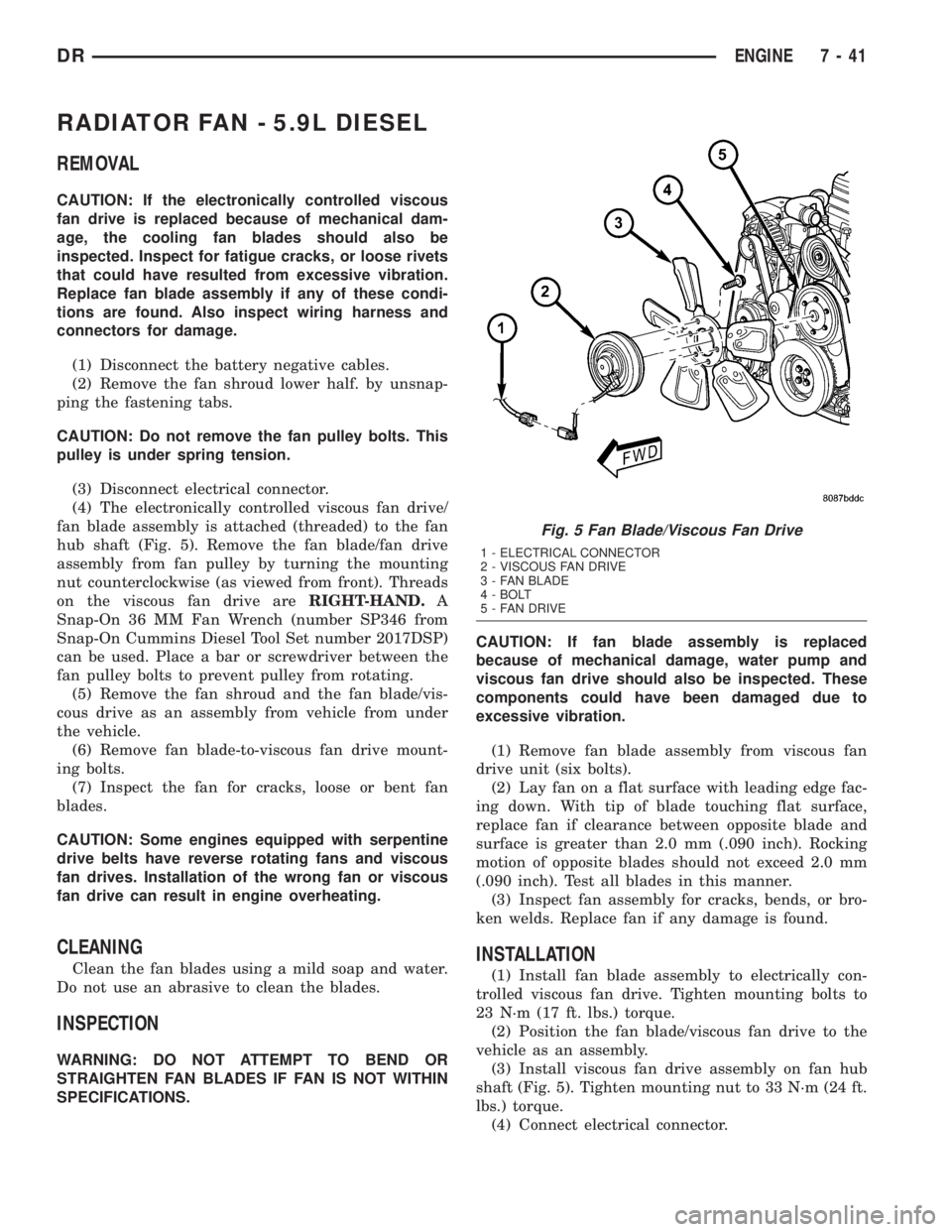
RADIATOR FAN - 5.9L DIESEL
REMOVAL
CAUTION: If the electronically controlled viscous
fan drive is replaced because of mechanical dam-
age, the cooling fan blades should also be
inspected. Inspect for fatigue cracks, or loose rivets
that could have resulted from excessive vibration.
Replace fan blade assembly if any of these condi-
tions are found. Also inspect wiring harness and
connectors for damage.
(1) Disconnect the battery negative cables.
(2) Remove the fan shroud lower half. by unsnap-
ping the fastening tabs.
CAUTION: Do not remove the fan pulley bolts. This
pulley is under spring tension.
(3) Disconnect electrical connector.
(4) The electronically controlled viscous fan drive/
fan blade assembly is attached (threaded) to the fan
hub shaft (Fig. 5). Remove the fan blade/fan drive
assembly from fan pulley by turning the mounting
nut counterclockwise (as viewed from front). Threads
on the viscous fan drive areRIGHT-HAND.A
Snap-On 36 MM Fan Wrench (number SP346 from
Snap-On Cummins Diesel Tool Set number 2017DSP)
can be used. Place a bar or screwdriver between the
fan pulley bolts to prevent pulley from rotating.
(5) Remove the fan shroud and the fan blade/vis-
cous drive as an assembly from vehicle from under
the vehicle.
(6) Remove fan blade-to-viscous fan drive mount-
ing bolts.
(7) Inspect the fan for cracks, loose or bent fan
blades.
CAUTION: Some engines equipped with serpentine
drive belts have reverse rotating fans and viscous
fan drives. Installation of the wrong fan or viscous
fan drive can result in engine overheating.
CLEANING
Clean the fan blades using a mild soap and water.
Do not use an abrasive to clean the blades.
INSPECTION
WARNING: DO NOT ATTEMPT TO BEND OR
STRAIGHTEN FAN BLADES IF FAN IS NOT WITHIN
SPECIFICATIONS.CAUTION: If fan blade assembly is replaced
because of mechanical damage, water pump and
viscous fan drive should also be inspected. These
components could have been damaged due to
excessive vibration.
(1) Remove fan blade assembly from viscous fan
drive unit (six bolts).
(2) Lay fan on a flat surface with leading edge fac-
ing down. With tip of blade touching flat surface,
replace fan if clearance between opposite blade and
surface is greater than 2.0 mm (.090 inch). Rocking
motion of opposite blades should not exceed 2.0 mm
(.090 inch). Test all blades in this manner.
(3) Inspect fan assembly for cracks, bends, or bro-
ken welds. Replace fan if any damage is found.
INSTALLATION
(1) Install fan blade assembly to electrically con-
trolled viscous fan drive. Tighten mounting bolts to
23 N´m (17 ft. lbs.) torque.
(2) Position the fan blade/viscous fan drive to the
vehicle as an assembly.
(3) Install viscous fan drive assembly on fan hub
shaft (Fig. 5). Tighten mounting nut to 33 N´m (24 ft.
lbs.) torque.
(4) Connect electrical connector.
Fig. 5 Fan Blade/Viscous Fan Drive
1 - ELECTRICAL CONNECTOR
2 - VISCOUS FAN DRIVE
3 - FAN BLADE
4 - BOLT
5 - FAN DRIVE
DRENGINE 7 - 41
Page 341 of 2895
(7) Start the engine and check for coolant leaks.
Run engine to check for proper thermostat operation.
FAN DRIVE VISCOUS CLUTCH
DESCRIPTION
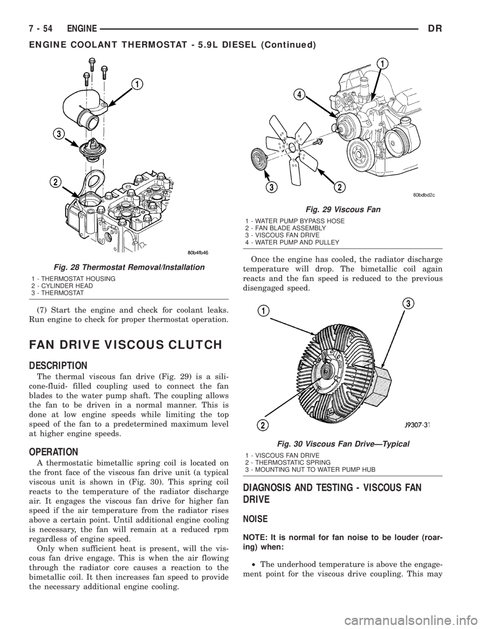
The thermal viscous fan drive (Fig. 29) is a sili-
cone-fluid- filled coupling used to connect the fan
blades to the water pump shaft. The coupling allows
the fan to be driven in a normal manner. This is
done at low engine speeds while limiting the top
speed of the fan to a predetermined maximum level
at higher engine speeds.
OPERATION
A thermostatic bimetallic spring coil is located on
the front face of the viscous fan drive unit (a typical
viscous unit is shown in (Fig. 30). This spring coil
reacts to the temperature of the radiator discharge
air. It engages the viscous fan drive for higher fan
speed if the air temperature from the radiator rises
above a certain point. Until additional engine cooling
is necessary, the fan will remain at a reduced rpm
regardless of engine speed.
Only when sufficient heat is present, will the vis-
cous fan drive engage. This is when the air flowing
through the radiator core causes a reaction to the
bimetallic coil. It then increases fan speed to provide
the necessary additional engine cooling.Once the engine has cooled, the radiator discharge
temperature will drop. The bimetallic coil again
reacts and the fan speed is reduced to the previous
disengaged speed.
DIAGNOSIS AND TESTING - VISCOUS FAN
DRIVE
NOISE
NOTE: It is normal for fan noise to be louder (roar-
ing) when:
²The underhood temperature is above the engage-
ment point for the viscous drive coupling. This may
Fig. 28 Thermostat Removal/Installation
1 - THERMOSTAT HOUSING
2 - CYLINDER HEAD
3 - THERMOSTAT
Fig. 29 Viscous Fan
1 - WATER PUMP BYPASS HOSE
2 - FAN BLADE ASSEMBLY
3 - VISCOUS FAN DRIVE
4 - WATER PUMP AND PULLEY
Fig. 30 Viscous Fan DriveÐTypical
1 - VISCOUS FAN DRIVE
2 - THERMOSTATIC SPRING
3 - MOUNTING NUT TO WATER PUMP HUB
7 - 54 ENGINEDR
ENGINE COOLANT THERMOSTAT - 5.9L DIESEL (Continued)
Page 1566 of 2895
CAMSHAFT & BEARINGS (IN
BLOCK)
REMOVAL
REMOVALÐCAMSHAFT BEARINGS
NOTE: Measure the diameter of each bore. If the
camshaft bore for the first or rear cam bushing is
worn beyond the limit, install a new service bush-
ing. Inspect the rest of the camshaft bores for dam-
age or excessive wear.If the bores without a
bushing are worn beyond the limit, the engine must
be removed for machining and installation of ser-
vice bushings. If badly worn, replace the cylinder
block.
(1) Remove the camshaft (Refer to 9 - ENGINE/
ENGINE BLOCK/CAMSHAFT & BEARINGS (IN
BLOCK) - REMOVAL).
(2) Remove the bushing from the No.1 bore and
No.7 using a universal cam bushing tool.
(3) Mark the cylinder block so you can align the oil
hole in the cylinder block with the oil hole in the
bushing.
REMOVAL - CAMSHAFT
(1) Disconnect both battery negative cables.
(2) Recover A/C refrigerant (if A/C equipped) (Refer
to 24 - HEATING & AIR CONDITIONING/PLUMB-
ING - STANDARD PROCEDURE).
(3) Raise vehicle on hoist.
(4) Drain engine coolant into container suitable for
re-use (Refer to 7 - COOLING - STANDARD PROCE-
DURE).
(5) Lower vehicle.
(6) Remove radiator upper hose.
(7) Remove viscous fan/drive assembly and fan
shroud (Refer to 7 - COOLING/ENGINE/RADIATOR
FAN - REMOVAL).
(8) Disconnect the coolant recovery bottle hose
from the radiator filler neck.
(9) Disconnect lower radiator hose from radiator
outlet.
(10)Automatic Transmission models:Discon-
nect transmission oil cooler lines from front of radia-
tor using Special Tool 6931 (unless equipped with
finger-release disconnect).
(11) Remove radiator mounting screws and lift
radiator out of engine compartment.
(12) Remove upper radiator support panel.
(13) If A/C equipped, disconnect A/C condenser
refrigerant lines.
(14) Disconnect charge air cooler piping from the
cooler inlet and outlet.(15) Remove the two charge air cooler mounting
bolts.
(16) Remove charge air cooler (and A/C condenser
if equipped) from vehicle.
(17) Remove accessory drive belt (Refer to 7 -
COOLING/ACCESSORY DRIVE/DRIVE BELTS -
REMOVAL).
(18) Remove accessory drive belt tensioner.
(19) Remove the fan support/hub assembly.
(20) Remove crankshaft damper and speed indica-
tor ring (Refer to 9 - ENGINE/ENGINE BLOCK/VI-
BRATION DAMPER - REMOVAL).
(21) Remove the gear cover-to-housing bolts and
gently pry the cover away from the housing, taking
care not to mar the sealing surfaces. Remove dust
seal with cover.
(22) Using Special Tool 7471±B Crankshaft Bar-
ring Tool, rotate the crankshaft to align the timing
marks on the crankshaft and the camshaft gears.
(23) Remove the cylinder head cover (Refer to 9 -
ENGINE/CYLINDER HEAD/CYLINDER HEAD
COVER(S) - REMOVAL).
(24) Remove the rocker arms, cross heads, and
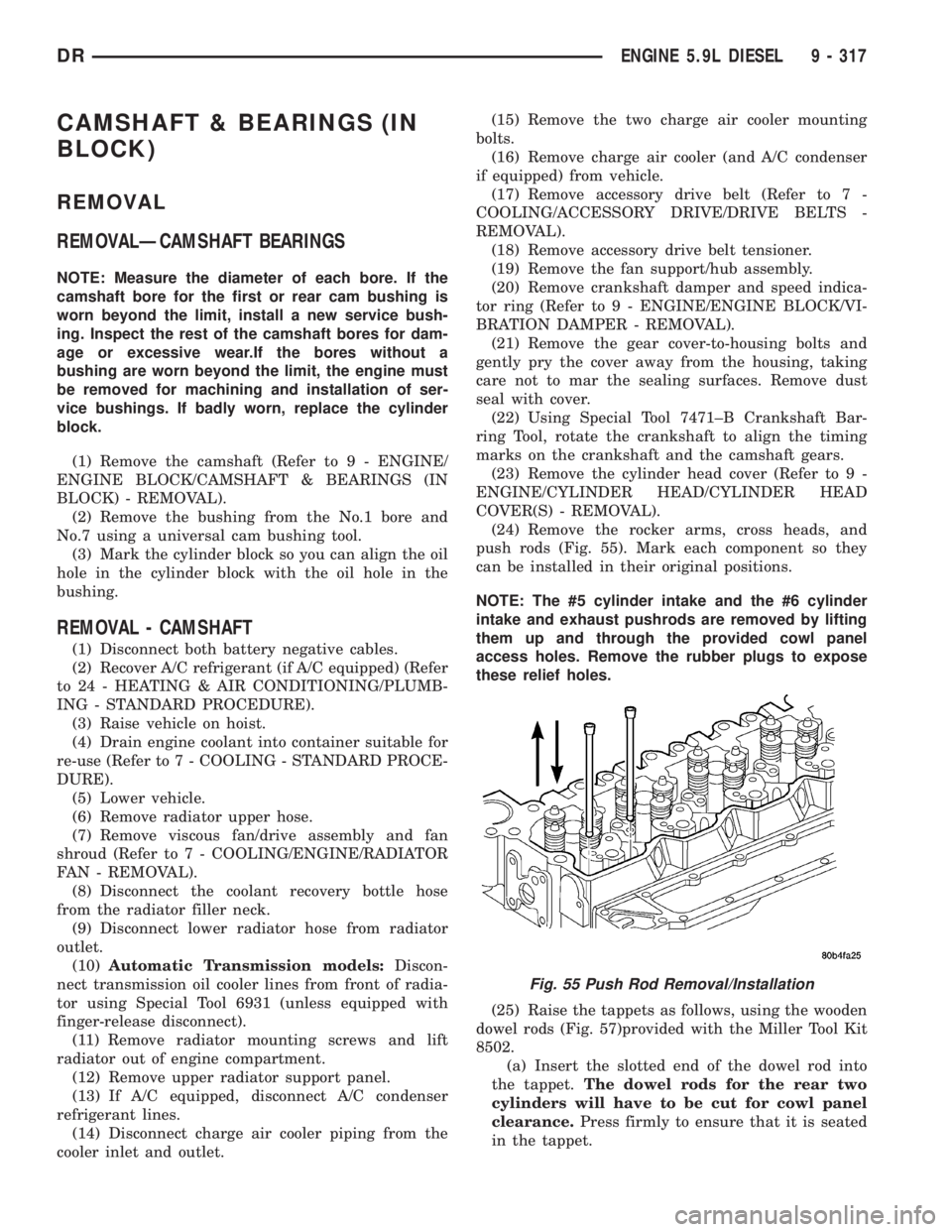
push rods (Fig. 55). Mark each component so they
can be installed in their original positions.
NOTE: The #5 cylinder intake and the #6 cylinder
intake and exhaust pushrods are removed by lifting
them up and through the provided cowl panel
access holes. Remove the rubber plugs to expose
these relief holes.
(25) Raise the tappets as follows, using the wooden
dowel rods (Fig. 57)provided with the Miller Tool Kit
8502.
(a) Insert the slotted end of the dowel rod into
the tappet.The dowel rods for the rear two
cylinders will have to be cut for cowl panel
clearance.Press firmly to ensure that it is seated
in the tappet.
Fig. 55 Push Rod Removal/Installation
DRENGINE 5.9L DIESEL 9 - 317
Page 1572 of 2895
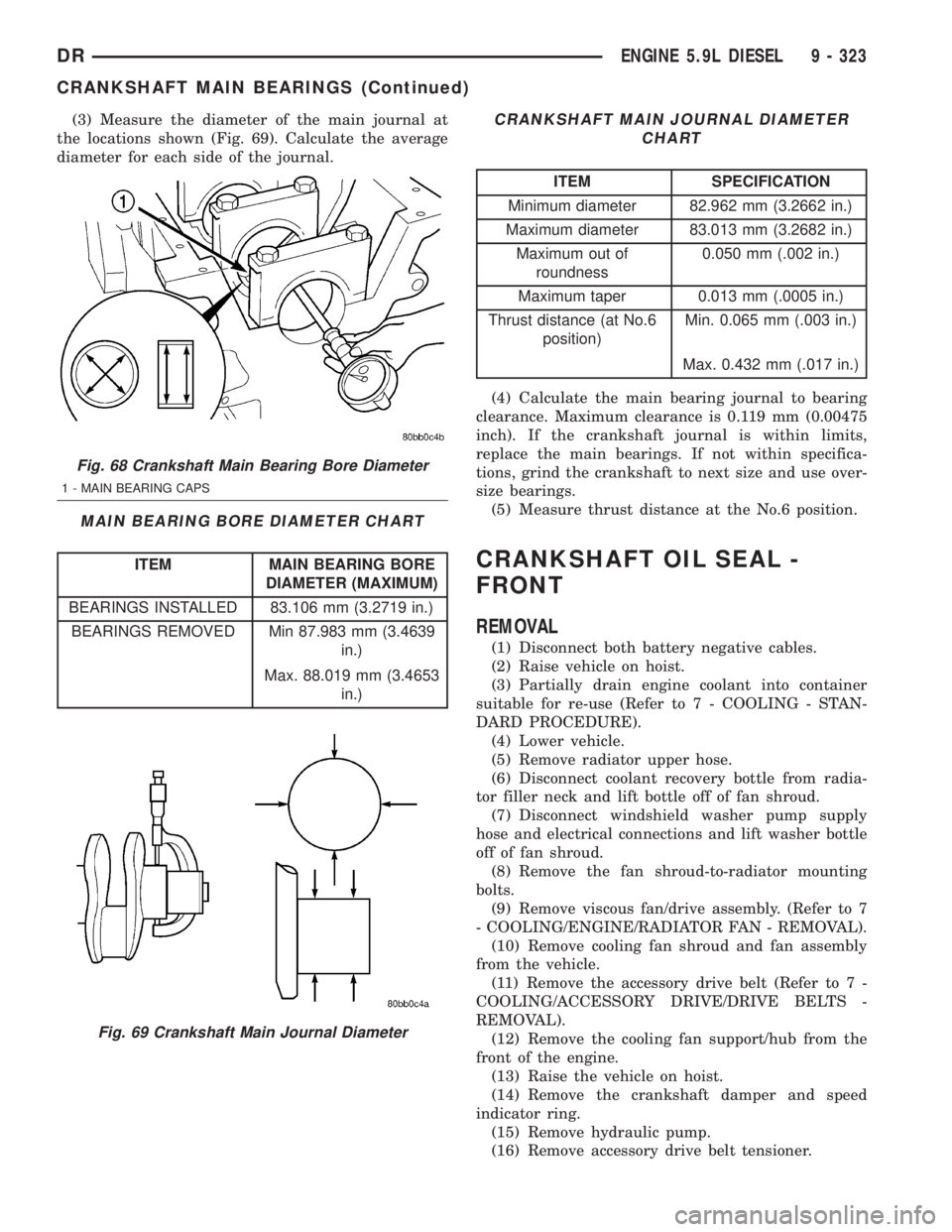
(3) Measure the diameter of the main journal at
the locations shown (Fig. 69). Calculate the average
diameter for each side of the journal.
MAIN BEARING BORE DIAMETER CHART
ITEM MAIN BEARING BORE
DIAMETER (MAXIMUM)
BEARINGS INSTALLED 83.106 mm (3.2719 in.)
BEARINGS REMOVED Min 87.983 mm (3.4639
in.)
Max. 88.019 mm (3.4653
in.)
CRANKSHAFT MAIN JOURNAL DIAMETER
CHART
ITEM SPECIFICATION
Minimum diameter 82.962 mm (3.2662 in.)
Maximum diameter 83.013 mm (3.2682 in.)
Maximum out of
roundness0.050 mm (.002 in.)
Maximum taper 0.013 mm (.0005 in.)
Thrust distance (at No.6
position)Min. 0.065 mm (.003 in.)
Max. 0.432 mm (.017 in.)
(4) Calculate the main bearing journal to bearing
clearance. Maximum clearance is 0.119 mm (0.00475
inch). If the crankshaft journal is within limits,
replace the main bearings. If not within specifica-
tions, grind the crankshaft to next size and use over-
size bearings.
(5) Measure thrust distance at the No.6 position.
CRANKSHAFT OIL SEAL -
FRONT
REMOVAL
(1) Disconnect both battery negative cables.
(2) Raise vehicle on hoist.
(3) Partially drain engine coolant into container
suitable for re-use (Refer to 7 - COOLING - STAN-
DARD PROCEDURE).
(4) Lower vehicle.
(5) Remove radiator upper hose.
(6) Disconnect coolant recovery bottle from radia-
tor filler neck and lift bottle off of fan shroud.
(7) Disconnect windshield washer pump supply
hose and electrical connections and lift washer bottle
off of fan shroud.
(8) Remove the fan shroud-to-radiator mounting
bolts.
(9) Remove viscous fan/drive assembly. (Refer to 7
- COOLING/ENGINE/RADIATOR FAN - REMOVAL).
(10) Remove cooling fan shroud and fan assembly
from the vehicle.
(11) Remove the accessory drive belt (Refer to 7 -
COOLING/ACCESSORY DRIVE/DRIVE BELTS -
REMOVAL).
(12) Remove the cooling fan support/hub from the
front of the engine.
(13) Raise the vehicle on hoist.
(14) Remove the crankshaft damper and speed
indicator ring.
(15) Remove hydraulic pump.
(16) Remove accessory drive belt tensioner.
Fig. 68 Crankshaft Main Bearing Bore Diameter
1 - MAIN BEARING CAPS
Fig. 69 Crankshaft Main Journal Diameter
DRENGINE 5.9L DIESEL 9 - 323
CRANKSHAFT MAIN BEARINGS (Continued)
Page 1574 of 2895
ring tool to keep the engine from rotating during
tightening operation.
(11) Install the fan support/hub assembly and
torque bolts to 32 N´m (24 ft. lbs.).
(12) Install hydraulic pump.
(13) Install accessory drive belt tensioner. Torque
bolt to 43 Nm (32 ft.lbs.).
(14) Install cooling fan (Refer to 7 - COOLING/EN-
GINE/RADIATOR FAN - INSTALLATION).
(15) Install the accessory drive belt (Refer to 7 -
COOLING/ACCESSORY DRIVE/DRIVE BELTS -
INSTALLATION).
(16) Refill cooling system (Refer to 7 - COOLING -
STANDARD PROCEDURE).
(17) Connect battery negative cables.
(18) Start engine and check for oil leaks.
CRANKSHAFT OIL SEAL -
REAR
REMOVAL
(1) Disconnect the battery negative cables.
(2) Remove the transmission and transfer case (if
equipped).
(3) Remove the clutch cover and disc (if manual
transmission equipped) (Refer to 6 - CLUTCH/
CLUTCH DISC - REMOVAL).
(4) Remove the flywheel or converter drive plate.
(5) Drill holes 180É apart into the seal. Be careful
not to contact the drill against the crankshaft.
(6) Install #10 sheet metal screws in the drilled
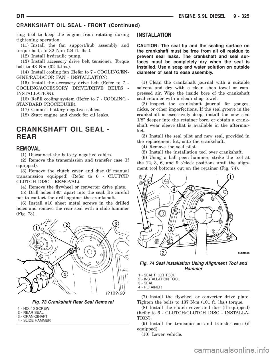
holes and remove the rear seal with a slide hammer
(Fig. 73).
INSTALLATION
CAUTION: The seal lip and the sealing surface on
the crankshaft must be free from all oil residue to
prevent seal leaks. The crankshaft and seal sur-
faces must be completely dry when the seal is
installed. Use a soap and water solution on outside
diameter of seal to ease assembly.
(1) Clean the crankshaft journal with a suitable
solvent and dry with a clean shop towel or com-
pressed air. Wipe the inside bore of the crankshaft
seal retainer with a clean shop towel.
(2) Inspect the crankshaft journal for gouges,
nicks, or other imperfections. If the seal groove in the
crankshaft is excessively deep, install the new seal
1/8º deeper into the retainer bore, or obtain a crank-
shaft wear sleeve that is available in the aftermar-
ket.
(3) Install the seal pilot and new seal, provided in
the replacement kit, onto the crankshaft.
(4) Remove the seal pilot.
(5) Install the installation tool over crankshaft.
(6) Using a ball peen hammer, strike the tool at
the 12, 3, 6, and 9 o'clock positions until the align-
ment tool bottoms out on the retainer (Fig. 74).
(7) Install the flywheel or converter drive plate.
Tighten the bolts to 137 N´m (101 ft. lbs.) torque.
(8) Install the clutch cover and disc (if equipped)
(Refer to 6 - CLUTCH/CLUTCH DISC - INSTALLA-
TION).
(9) Install the transmission and transfer case (if
equipped).
(10) Lower vehicle.
Fig. 73 Crankshaft Rear Seal Removal
1 - NO. 10 SCREW
2 - REAR SEAL
3 - CRANKSHAFT
4 - SLIDE HAMMER
Fig. 74 Seal Installation Using Alignment Tool and
Hammer
1 - SEAL PILOT TOOL
2 - INSTALLATION TOOL
3 - SEAL
4 - RETAINER
DRENGINE 5.9L DIESEL 9 - 325
CRANKSHAFT OIL SEAL - FRONT (Continued)
Page 1584 of 2895
VIBRATION DAMPER
REMOVAL
(1) Remove the accessory drive belt (Refer to 7 -
COOLING/ACCESSORY DRIVE/DRIVE BELTS -
REMOVAL).
(2) Remove the four (4) damper to crankshaft bolts
and remove damper and speed indicator ring.
INSPECTION
(1) Inspect the damper hub for cracks and replace
if any are found.
(2) Inspect the index lines on the damper hub and
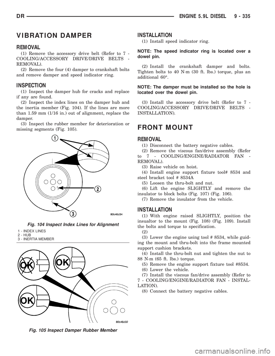
the inertia member (Fig. 104). If the lines are more
than 1.59 mm (1/16 in.) out of alignment, replace the
damper.
(3) Inspect the rubber member for deterioration or
missing segments (Fig. 105).
INSTALLATION
(1) Install speed indicator ring.
NOTE: The speed indicator ring is located over a
dowel pin.
(2) Install the crankshaft damper and bolts.
Tighten bolts to 40 N´m (30 ft. lbs.) torque, plus an
additional 60É.
NOTE: The damper must be installed so the hole is
located over the dowel pin.
(3) Install the accessory drive belt (Refer to 7 -
COOLING/ACCESSORY DRIVE/DRIVE BELTS -
INSTALLATION).
FRONT MOUNT
REMOVAL
(1) Disconnect the battery negative cables.
(2) Remove the viscous fan/drive assembly (Refer
to 7 - COOLING/ENGINE/RADIATOR FAN -
REMOVAL).
(3) Raise vehicle on hoist.
(4) Install engine support fixture tool# 8534 and
steel bracket tool # 8534A
(5) Loosen the thru-bolt and nut.
(6) Lift the engine SLIGHTLY and remove the
insulator to block bolts (Fig. 107) (Fig. 106).
(7) Remove the insulator from the vehicle.
INSTALLATION
(1) With engine raised SLIGHTLY, position the
insualtor to the mount (Fig. 108) (Fig. 109). Install
the bolts and torque to specification.
(2)
(3) Lower the engine using tool # 8534, while guid-
ing the mount and thru-bolt into the frame mounted
support cushion brackets.
(4) Install the thru-bolt nut and tighten the nut to
88 N´m (65 ft. lbs.) torque.
(5) Remove the engine support fixture tool #8534.
(6) Lower the vehicle.
(7) Install the viscous fan/drive assembly (Refer to
7 - COOLING/ENGINE/RADIATOR FAN - INSTAL-
LATION).
(8) Connect the battery negative cables.
Fig. 104 Inspect Index Lines for Alignment
1 - INDEX LINES
2 - HUB
3 - INERTIA MEMBER
Fig. 105 Inspect Damper Rubber Member
DRENGINE 5.9L DIESEL 9 - 335
Page 1597 of 2895
(8) Install the oil drain tube and a new gasket to
the turbocharger. Tighten the drain tube bolts to 24
N´m (18 ft. lbs.) torque.
(9)Pre-lube the turbocharger.Pour 50 to 60 cc
(2 to 3 oz.) clean engine oil in the oil supply line fit-
ting on the turbo. Rotate the turbocharger impeller
by hand to distrubute the oil thoroughly.
(10) Install and tighten the oil supply line fitting
nut to 24 N´m (18 ft. lbs.) torque.
(11) Position the charge air cooler inlet pipe to the
turbocharger. With the clamp in position, tighten the
clamp nut to 8 N´m (72 in. lbs.) torque.
(12) Position the air inlet hose to the turbocharger.
Tighten the clamp to 8 N´m (72 in. lbs.) torque.
(13) Raise vehicle on hoist.
(14) Connect the exhaust pipe to the turbocharger
and tighten the bolts to 34 N´m (25 ft. lbs.) torque.
(15) Lower the vehicle.
(16) Connect the battery negative cables.
(17) Start the engine to check for leaks.
VALVE TIMING
STANDARD PROCEDURE - TIMING
VERIFICATION
(1) Remove the cylinder head cover(Refer to 9 -
ENGINE/CYLINDER HEAD/CYLINDER HEAD
COVER(S) - REMOVAL).
(2) Remove fuel injector from cylinder number
1(Refer to 14 - FUEL SYSTEM/FUEL INJECTION/
FUEL INJECTOR - REMOVAL).
(3) Using Special Tool 7471B rotate the engine
until the TDC mark on the damper is at 12 o'clock.
(4) Using a 8 in.x 1/4 in. dowel rod inserted into
cylinder number 1, rock the crankshaft back and
forth to verify piston number 1 is at TDC.
(5) With cylinder number still at TDC, inspect the
keyway on the crankshaft gear for proper alignment
(12 o'clock position).
(6) If the keyway is not at 12 o'clock position
replace the crankshaft gear assembly.
(7) If the keyway is at 12 o'clock position, remove
front gear cover and verify timing mark alignment
between the camshaft gear and crankshaft gear, if
not aligned inspect keyway on camshaft gear.
(8) Inspect keyway on camshaft gear for proper
alignment with the key in the camshaft, if alignment
is off replace the camshaft/gear assembly.
(9) If timing marks alignment is off and no dam-
age is found at either the crankshaft or camshaft
gear keyways, realign timing marks as necessary.
GEAR HOUSING
REMOVAL
(1) Disconnect the battery negative cables.
(2) Raise vehicle on hoist.
(3) Partially drain engine coolant into container
suitable for re-use (Refer to 7 - COOLING - STAN-
DARD PROCEDURE).
(4) Lower vehicle.
(5) Remove radiator upper hose.
(6) Disconnect coolant recovery bottle hose from
radiator filler neck and lift bottle off of fan shroud.
(7) Disconnect windshield washer pump supply
hose and electrical connections and lift washer bottle
off of fan shroud.
(8) Remove lower fan shroud fasteners. Disconnect
fan drive wire harness.
(9) Remove the upper fan shroud-to-radiator
mounting bolts.
(10) Remove viscous fan/drive assembly (Refer to 7
- COOLING/ENGINE/RADIATOR FAN - REMOVAL).
(11) Remove the accessory drive belt (Refer to 7 -
COOLING/ACCESSORY DRIVE/DRIVE BELTS -
REMOVAL).
(12) Remove the cooling fan support/hub from the
front of the engine.
(13) Raise the vehicle on hoist.
(14) Remove the crankshaft damper (Refer to 9 -
ENGINE/ENGINE BLOCK/VIBRATION DAMPER -
REMOVAL) and speed indicator ring.
(15) Lower the vehicle.
(16) Remove the hydraulic pump.
(17) Remove the accessory drive belt tensioner.
(18) Remove the gear cover-to-housing bolts and
gently pry the cover away from the housing, taking
care not to mar the gasket surfaces.
(19) Remove the fuel injection pump (Refer to 14 -
FUEL SYSTEM/FUEL DELIVERY/FUEL INJEC-
TION PUMP - REMOVAL).
(20) Disconnect the camshaft position sensor con-
nector.
(21) Disconnect and remove engine speed sensor.
(22) Remove the camshaft (Refer to 9 - ENGINE/
ENGINE BLOCK/CAMSHAFT & BEARINGS (IN
BLOCK) - REMOVAL).
(23) Remove the six front oil pan fasteners.
(24) Remove the gear housing fasteners.
NOTE: Use care when removing the gear housing,
to avoid damage to the oil pan gasket, as the gas-
ket will be reused if it is not damaged.
(25) Slide a feeler gauge between the gear housing
and oil pan gasket, to break the gasket seal.
(26) Remove the gear housing and gasket.
9 - 348 ENGINE 5.9L DIESELDR
EXHAUST MANIFOLD (Continued)