2003 DODGE RAM Front hub assembly
[x] Cancel search: Front hub assemblyPage 1598 of 2895
(27) Clean the gasket material from the cylinder
block and gear housing.
INSTALLATION
(1) Inspect oil pan gasket. If torn, gasket must be
replaced.
(2) Install a new gasket and the gear housing.
Torque bolts to 24 N´m (18 ft. lbs.). Follow torque
sequence.
(3) If a new housing is installed, the camshaft
position sensor, and engine speed sensor must be
transferred to the new housing.
(4) Connect the camshaft position sensor connec-
tor.
(5) Install and connect engine speed sensor.
(6) Install the injection pump (Refer to 14 - FUEL
SYSTEM/FUEL DELIVERY/FUEL INJECTION
PUMP - INSTALLATION).
(7) Install the camshaft (Refer to 9 - ENGINE/EN-
GINE BLOCK/CAMSHAFT & BEARINGS (IN
BLOCK) - INSTALLATION). Align the crankshaft
and camshaft gear marks as shown in.
(8) Install a new front crankshaft seal into the
gear cover.
(9) Apply a bead of MopartSilicone Rubber Adhe-
sive Sealant or equivalent to the gear housing cover.
Be sure to surround all through holes.
(10) Using the seal pilot to align the cover, install
the cover to the housing and install the bolts.
Tighten the bolts to 24 N´m (18 ft. lbs.) torque.
(11) Remove the seal pilot. Install front seal dust
shield.
(12) Raise the vehicle.
(13) Trim any excess gear housing gasket to make
it flush with the oil pan rail.
(14) Install the crankshaft damper and speed indi-
cator ring (Refer to 9 - ENGINE/ENGINE BLOCK/
VIBRATION DAMPER - INSTALLATION). Torque
bolts to 40 Nm (30 ft. lbs.), plus an additional 60É.
(15) Lower vehicle.
(16) Install the fan support/hub assembly and
tighten bolts to 32 N´m (24 ft. lbs.) torque.
(17) Install the hydraulic pump.
(18) Install the accessory drive belt tensioner.
Torque bolt to 43 N´m (32 ft. lbs.) torque.
(19) Install the accessory drive belt (Refer to 7 -
COOLING/ACCESSORY DRIVE/DRIVE BELTS -
INSTALLATION).
(20) Install the upper cooling fan and shroud
together (Refer to 7 - COOLING/ENGINE/RADIA-
TOR FAN - INSTALLATION).(21) Install lower shroud and connect fan drive
harness connector.
(22) Install the windshield washer reservoir to the
fan shroud and connect the washer pump supply
hose and electrical connection.
(23) Install the coolant recovery bottle to the fan
shroud and connect the hose to the radiator filler
neck.
(24) Install the radiator upper hose and clamps.
(25) Add engine oil.
(26) Add coolant (Refer to 7 - COOLING - STAN-
DARD PROCEDURE).
(27) Connect the battery cables.
(28) Start engine and inspect for leaks.
GEAR HOUSING COVER
REMOVAL
(1) Disconnect both battery negative cables.
(2) Raise vehicle on hoist.
(3) Partially drain engine coolant into container
suitable for re-use (Refer to 7 - COOLING - STAN-
DARD PROCEDURE).
(4) Lower vehicle.
(5) Remove radiator upper hose.
(6) Disconnect coolant recovery bottle hose from
radiator filler neck and lift bottle off of fan shroud.
(7) Disconnect windshield washer pump supply
hose and electrical connections and lift washer bottle
off of fan shroud.
(8) Remove viscous fan/drive assembly (Refer to 7 -
COOLING/ENGINE/RADIATOR FAN - REMOVAL).
(9) Remove the accessory drive belt (Refer to 7 -
COOLING/ACCESSORY DRIVE/DRIVE BELTS -
REMOVAL).
(10) Remove the cooling fan support/hub from the
front of the engine.
(11) Raise the vehicle on hoist.
(12) Remove power steering pump.
(13) Remove accessory drive belt tensioner.
(14) Remove the crankshaft damper and speed
indicator ring (Refer to 9 - ENGINE/ENGINE
BLOCK/VIBRATION DAMPER - REMOVAL).
(15) Lower the vehicle.
(16) Remove the gear cover-to-housing bolts and
gently pry the cover away from the housing, taking
care not to mar the gasket surfaces.
DRENGINE 5.9L DIESEL 9 - 349
GEAR HOUSING (Continued)
Page 1840 of 2895
TRANSMISSION AND TRANSFER CASE
TABLE OF CONTENTS
page page
MANUAL TRANSMISSION - NV3500..........1
MANUAL TRANSMISSION - NV4500..........42
MANUAL TRANSMISSION - NV5600..........87
AUTOMATIC TRANSMISSION - 46RE........129
AUTOMATIC TRANSMISSION - 48RE........310
AUTOMATIC TRANSMISSION - 45RFE/545RFE. . 488
TRANSFER CASE - NV241 GENII...........591
TRANSFER CASE - NV271................623
TRANSFER CASE - NV243................658
TRANSFER CASE - NV273................687
MANUAL TRANSMISSION - NV3500
TABLE OF CONTENTS
page page
MANUAL TRANSMISSION - NV3500
DESCRIPTION..........................1
OPERATION............................1
DIAGNOSIS AND TESTING................3
REMOVAL.............................3
DISASSEMBLY..........................4CLEANING............................15
INSPECTION..........................15
ASSEMBLY............................17
INSTALLATION.........................38
SPECIFICATIONS.......................39
SPECIAL TOOLS.......................40
MANUAL TRANSMISSION -
NV3500
DESCRIPTION
The transmission is a medium-duty 5-speed, con-
stant mesh fully synchronized manual transmission
with fifth gear overdrive range. The transmission is
available in two and four-wheel drive configurations.
The transmission gear case consists of two aluminum
housings (Fig. 1). The clutch housing is an integral
part of the transmission front housing.
A combination of roller and ball bearings are used
to support the transmission shafts in the two hous-
ings. The transmission gears all rotate on caged type
needle bearings. A roller bearing is used between the
input and output shaft.
The transmission has a single shaft shift mecha-
nism with three shift forks all mounted on the shaft.
The shaft is supported in the front and rear housings
by bushings and one linear ball bearing. Internal
shift components consist of the forks, shaft, shift
lever socket and detent components
OPERATION
The manual transmission receives power through the
clutch assembly from the engine. The clutch disc issplined to the transmission input shaft and is turned at
engine speed at all times that the clutch is engaged.
The input shaft is connected to the transmission coun-
tershaft through the mesh of fourth speed gear on the
input shaft and the fourth countershaft gear. At this
point, all the transmission gears are spinning.
The driver selects a particular gear by moving the
shift lever to the desired gear position. This move-
ment moves the internal transmission shift compo-
nents to begin the shift sequence. As the shift lever
moves the selected shift rail, the shift fork attached
to that rail begins to move. The fork is positioned in
a groove in the outer circumference of the synchro-
nizer sleeve. As the shift fork moves the synchronizer
sleeve, the synchronizer begins to speed-up or slow
down the selected gear (depending on whether we are
up-shifting or down-shifting). The synchronizer does
this by having the synchronizer hub splined to the
mainshaft and moving the blocker ring into contact
with the gear's friction cone. As the blocker ring and
friction cone come together, the gear speed is brought
up or down to the speed of the synchronizer. As the
two speeds match, the splines on the inside of the
synchronizer sleeve become aligned with the teeth on
the blocker ring and the friction cone and eventually
will slide over the teeth, locking the gear to the
mainshaft, or countershaft, through the synchronizer.
DRTRANSMISSION AND TRANSFER CASE 21 - 1
Page 1857 of 2895
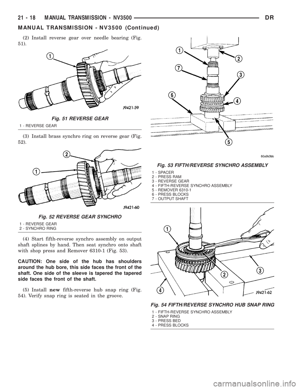
(2) Install reverse gear over needle bearing (Fig.
51).
(3) Install brass synchro ring on reverse gear (Fig.
52).
(4) Start fifth-reverse synchro assembly on output
shaft splines by hand. Then seat synchro onto shaft
with shop press and Remover 6310-1 (Fig. 53).
CAUTION: One side of the hub has shoulders
around the hub bore, this side faces the front of the
shaft. One side of the sleeve is tapered the tapered
side faces the front of the shaft.
(5) Installnewfifth-reverse hub snap ring (Fig.
54). Verify snap ring is seated in the groove.
Fig. 51 REVERSE GEAR
1 - REVERSE GEAR
Fig. 52 REVERSE GEAR SYNCHRO
1 - REVERSE GEAR
2 - SYNCHRO RING
Fig. 53 FIFTH/REVERSE SYNCHRO ASSEMBLY
1 - SPACER
2 - PRESS RAM
3 - REVERSE GEAR
4 - FIFTH-REVERSE SYNCHRO ASSEMBLY
5 - REMOVER 6310-1
6 - PRESS BLOCKS
7 - OUTPUT SHAFT
Fig. 54 FIFTH/REVERSE SYNCHRO HUB SNAP RING
1 - FIFTH-REVERSE SYNCHRO ASSEMBLY
2 - SNAP RING
3 - PRESS BED
4 - PRESS BLOCKS
21 - 18 MANUAL TRANSMISSION - NV3500DR
MANUAL TRANSMISSION - NV3500 (Continued)
Page 1862 of 2895
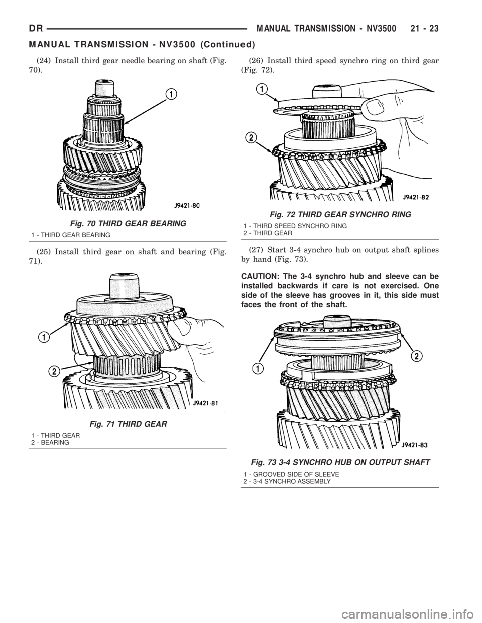
(24) Install third gear needle bearing on shaft (Fig.
70).
(25) Install third gear on shaft and bearing (Fig.
71).(26) Install third speed synchro ring on third gear
(Fig. 72).
(27) Start 3-4 synchro hub on output shaft splines
by hand (Fig. 73).
CAUTION: The 3-4 synchro hub and sleeve can be
installed backwards if care is not exercised. One
side of the sleeve has grooves in it, this side must
faces the front of the shaft.
Fig. 70 THIRD GEAR BEARING
1 - THIRD GEAR BEARING
Fig. 71 THIRD GEAR
1 - THIRD GEAR
2 - BEARING
Fig. 72 THIRD GEAR SYNCHRO RING
1 - THIRD SPEED SYNCHRO RING
2 - THIRD GEAR
Fig. 73 3-4 SYNCHRO HUB ON OUTPUT SHAFT
1 - GROOVED SIDE OF SLEEVE
2 - 3-4 SYNCHRO ASSEMBLY
DRMANUAL TRANSMISSION - NV3500 21 - 23
MANUAL TRANSMISSION - NV3500 (Continued)
Page 1866 of 2895
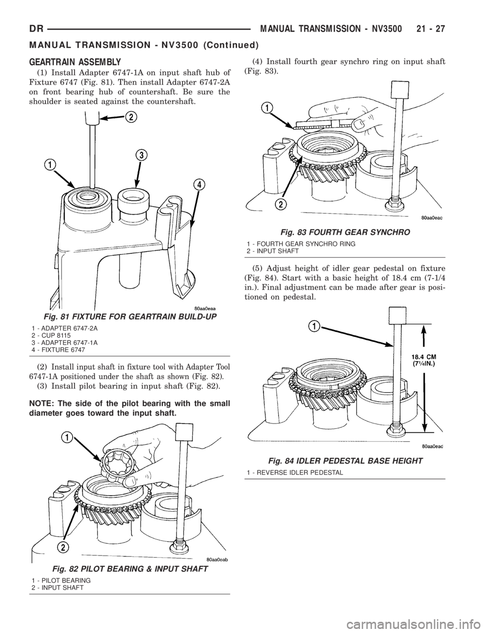
GEARTRAIN ASSEMBLY
(1) Install Adapter 6747-1A on input shaft hub of
Fixture 6747 (Fig. 81). Then install Adapter 6747-2A
on front bearing hub of countershaft. Be sure the
shoulder is seated against the countershaft.
(2)
Install input shaft in fixture tool with Adapter Tool
6747-1A positioned under the shaft as shown (Fig. 82).
(3) Install pilot bearing in input shaft (Fig. 82).
NOTE: The side of the pilot bearing with the small
diameter goes toward the input shaft.(4) Install fourth gear synchro ring on input shaft
(Fig. 83).
(5) Adjust height of idler gear pedestal on fixture
(Fig. 84). Start with a basic height of 18.4 cm (7-1/4
in.). Final adjustment can be made after gear is posi-
tioned on pedestal.
Fig. 81 FIXTURE FOR GEARTRAIN BUILD-UP
1 - ADAPTER 6747-2A
2 - CUP 8115
3 - ADAPTER 6747-1A
4 - FIXTURE 6747
Fig. 82 PILOT BEARING & INPUT SHAFT
1 - PILOT BEARING
2 - INPUT SHAFT
Fig. 83 FOURTH GEAR SYNCHRO
1 - FOURTH GEAR SYNCHRO RING
2 - INPUT SHAFT
Fig. 84 IDLER PEDESTAL BASE HEIGHT
1 - REVERSE IDLER PEDESTAL
DRMANUAL TRANSMISSION - NV3500 21 - 27
MANUAL TRANSMISSION - NV3500 (Continued)
Page 1867 of 2895
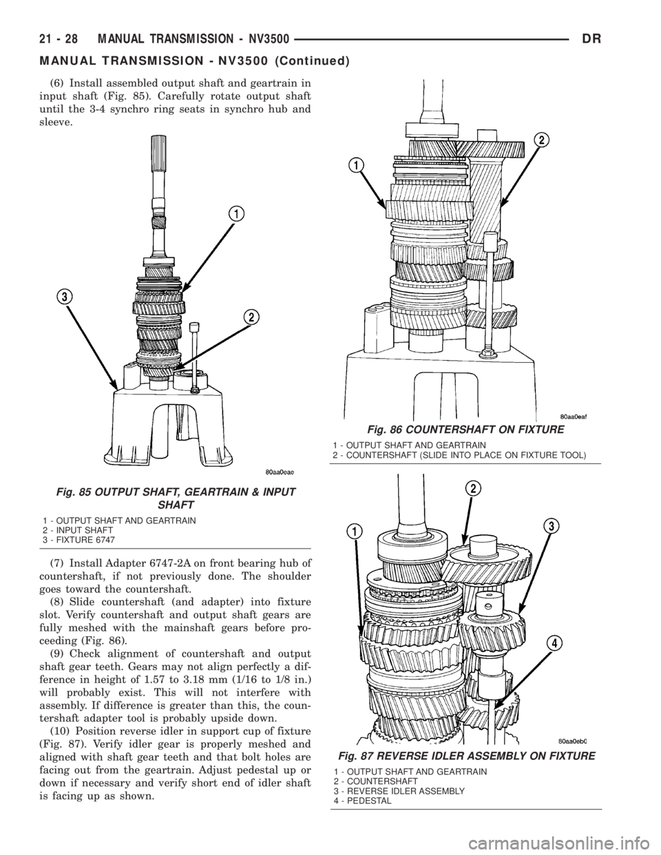
(6) Install assembled output shaft and geartrain in
input shaft (Fig. 85). Carefully rotate output shaft
until the 3-4 synchro ring seats in synchro hub and
sleeve.
(7) Install Adapter 6747-2A on front bearing hub of
countershaft, if not previously done. The shoulder
goes toward the countershaft.
(8) Slide countershaft (and adapter) into fixture
slot. Verify countershaft and output shaft gears are
fully meshed with the mainshaft gears before pro-
ceeding (Fig. 86).
(9) Check alignment of countershaft and output
shaft gear teeth. Gears may not align perfectly a dif-
ference in height of 1.57 to 3.18 mm (1/16 to 1/8 in.)
will probably exist. This will not interfere with
assembly. If difference is greater than this, the coun-
tershaft adapter tool is probably upside down.
(10) Position reverse idler in support cup of fixture
(Fig. 87). Verify idler gear is properly meshed and
aligned with shaft gear teeth and that bolt holes are
facing out from the geartrain. Adjust pedestal up or
down if necessary and verify short end of idler shaft
is facing up as shown.
Fig. 86 COUNTERSHAFT ON FIXTURE
1 - OUTPUT SHAFT AND GEARTRAIN
2 - COUNTERSHAFT (SLIDE INTO PLACE ON FIXTURE TOOL)
Fig. 87 REVERSE IDLER ASSEMBLY ON FIXTURE
1 - OUTPUT SHAFT AND GEARTRAIN
2 - COUNTERSHAFT
3 - REVERSE IDLER ASSEMBLY
4 - PEDESTAL
Fig. 85 OUTPUT SHAFT, GEARTRAIN & INPUT
SHAFT
1 - OUTPUT SHAFT AND GEARTRAIN
2 - INPUT SHAFT
3 - FIXTURE 6747
21 - 28 MANUAL TRANSMISSION - NV3500DR
MANUAL TRANSMISSION - NV3500 (Continued)
Page 1882 of 2895
The driver selects a particular gear by moving the
shift lever to the desired gear position. This move-
ment moves the internal transmission shift compo-
nents to begin the shift sequence. As the shift lever
moves the selected shift rail, the shift fork attached
to that rail begins to move. The fork is positioned in
a groove in the outer circumference of the synchro-
nizer sleeve. As the shift fork moves the synchronizer
sleeve, the synchronizer begins to speed-up or slow
down the selected gear (depending on whether the
driver is up-shifting or down-shifting). The synchro-
nizer does this by having the synchronizer hub
splined to the mainshaft, or the countershaft in some
cases, and moving the blocker ring into contact with
the gear's friction cone. As the blocker ring and fric-
tion cone come together, the gear speed is brought up
or down to the speed of the synchronizer. As the two
speeds match, the splines on the inside of the syn-
chronizer sleeve become aligned with the teeth on
the blocker ring and the friction cone and eventually
will slide over the teeth, locking the gear to the
mainshaft, or countershaft, through the synchronizer.
DIAGNOSIS AND TESTING
LOW LUBRICANT LEVEL
A low transmission lubricant level is generally the
result of a leak, inadequate lubricant fill or an incor-
rect lubricant level check. A correct lubricant level
check can only be made when the vehicle is level.
Also allow the lubricant to settle for a minute or so
before checking. These recommendations will ensure
an accurate check and avoid an underfill or overfill
condition. Always check the lubricant level after any
addition of fluid to avoid an incorrect lubricant level
condition.
Leaks can occur at the mating surfaces of the gear
case, adaptor or extension housing, or from the front/
rear seals. A suspected leak could also be the result
of an overfill condition. Leaks at the rear of the
extension or adapter housing will be from the hous-
ing oil seals. Leaks at component mating surfaces
will probably be the result of inadequate sealer, gaps
in the sealer, incorrect bolt tightening or use of a
non-recommended sealer. A leak at the front of the
transmission will be from either the front bearing
retainer or retainer seal. Lubricant may be seen drip-
ping from the clutch housing after extended opera-
tion. If the leak is severe, it may also contaminate
the clutch disc causing the disc to slip, grab and or
chatter.
HARD SHIFTING
Hard shifting is usually caused by a low lubricant
level, improper or contaminated lubricants. The con-
sequence of using non-recommended lubricants isnoise, excessive wear, internal bind and hard shift-
ing. Substantial lubricant leaks can result in gear,
shift rail, synchro, and bearing damage. If a leak
goes undetected for an extended period, the first indi-
cations of component damage are usually hard shift-
ing and noise.
Component damage, incorrect clutch adjustment or
damaged clutch pressure plate or disc are additional
probable causes of increased shift effort. Incorrect
adjustment or a worn/damaged pressure plate or disc
can cause incorrect release. If clutch problem is
advanced, gear clash during shifts can result. Worn
or damaged synchro rings can cause gear clash when
shifting into any forward gear. In some new or
rebuilt transmissions, new synchro rings may tend to
stick slightly causing hard or noisy shifts. In most
cases this condition will decline as the rings wear-in.
TRANSMISSION NOISE
Most manual transmissions make some noise dur-
ing normal operation. Rotating gears generate a mild
whine that is audible, but generally only at extreme
speeds. Severe highly audible transmission noise is
generally the initial indicator of a lubricant problem.
Insufficient, improper or contaminated lubricant
will promote rapid wear of gears, synchros, shift
rails, forks and bearings. The overheating caused by
a lubricant problem, can also lead to gear breakage.
REMOVAL
(1) Shift transmission into Neutral.
(2) Remove shift boot screws from floorpan and
slide boot upward on the shift lever.
(3) Remove shift lever extension from shift tower
and lever assembly.
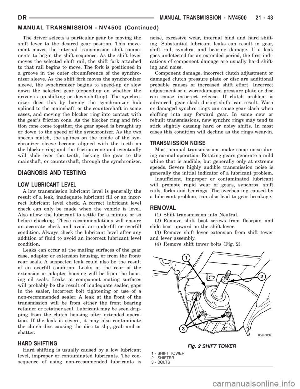
(4) Remove shift tower bolts (Fig. 2).
Fig. 2 SHIFT TOWER
1 - SHIFT TOWER
2 - SHIFTER
3 - BOLTS
DRMANUAL TRANSMISSION - NV4500 21 - 43
MANUAL TRANSMISSION - NV4500 (Continued)
Page 1893 of 2895
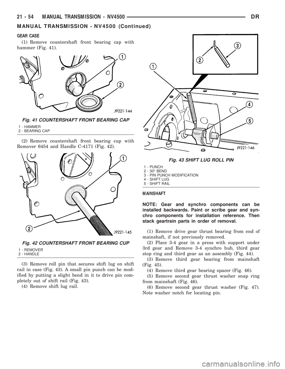
GEAR CASE
(1) Remove countershaft front bearing cap with
hammer (Fig. 41).
(2) Remove countershaft front bearing cup with
Remover 6454 and Handle C-4171 (Fig. 42).
(3) Remove roll pin that secures shift lug on shift
rail in case (Fig. 43). A small pin punch can be mod-
ified by putting a slight bend in it to drive pin com-
pletely out of shift rail (Fig. 43).
(4) Remove shift lug rail.MAINSHAFT
NOTE: Gear and synchro components can be
installed backwards. Paint or scribe gear and syn-
chro components for installation reference. Then
stack geartrain parts in order of removal.
(1) Remove drive gear thrust bearing from end of
mainshaft, if not previously removed.
(2) Place 3-4 gear in a press with support under
3rd gear and Remove 3-4 synchro hub, third gear
stop ring and third gear as an assembly (Fig. 44).
(3) Remove third gear bearing from mainshaft
(Fig. 45).
(4) Remove third gear bearing spacer (Fig. 46).
(5) Remove second gear thrust washer snap ring
from mainshaft (Fig. 46).
(6) Remove second gear thrust washer (Fig. 47).
Note washer notch for locating pin.
Fig. 41 COUNTERSHAFT FRONT BEARING CAP
1 - HAMMER
2 - BEARING CAP
Fig. 42 COUNTERSHAFT FRONT BEARING CUP
1 - REMOVER
2 - HANDLE
Fig. 43 SHIFT LUG ROLL PIN
1 - PUNCH
2 - 30É BEND
3 - PIN PUNCH MODIFICATION
4 - SHIFT LUG
5 - SHIFT RAIL
21 - 54 MANUAL TRANSMISSION - NV4500DR
MANUAL TRANSMISSION - NV4500 (Continued)