2003 DODGE RAM Front hub assembly
[x] Cancel search: Front hub assemblyPage 2264 of 2895
slots in face of gear carrier. Use extra petroleum jelly
to hold washer in place if desired.
(11) Install the torlon bushing onto the front plan-
etary carrier hub.
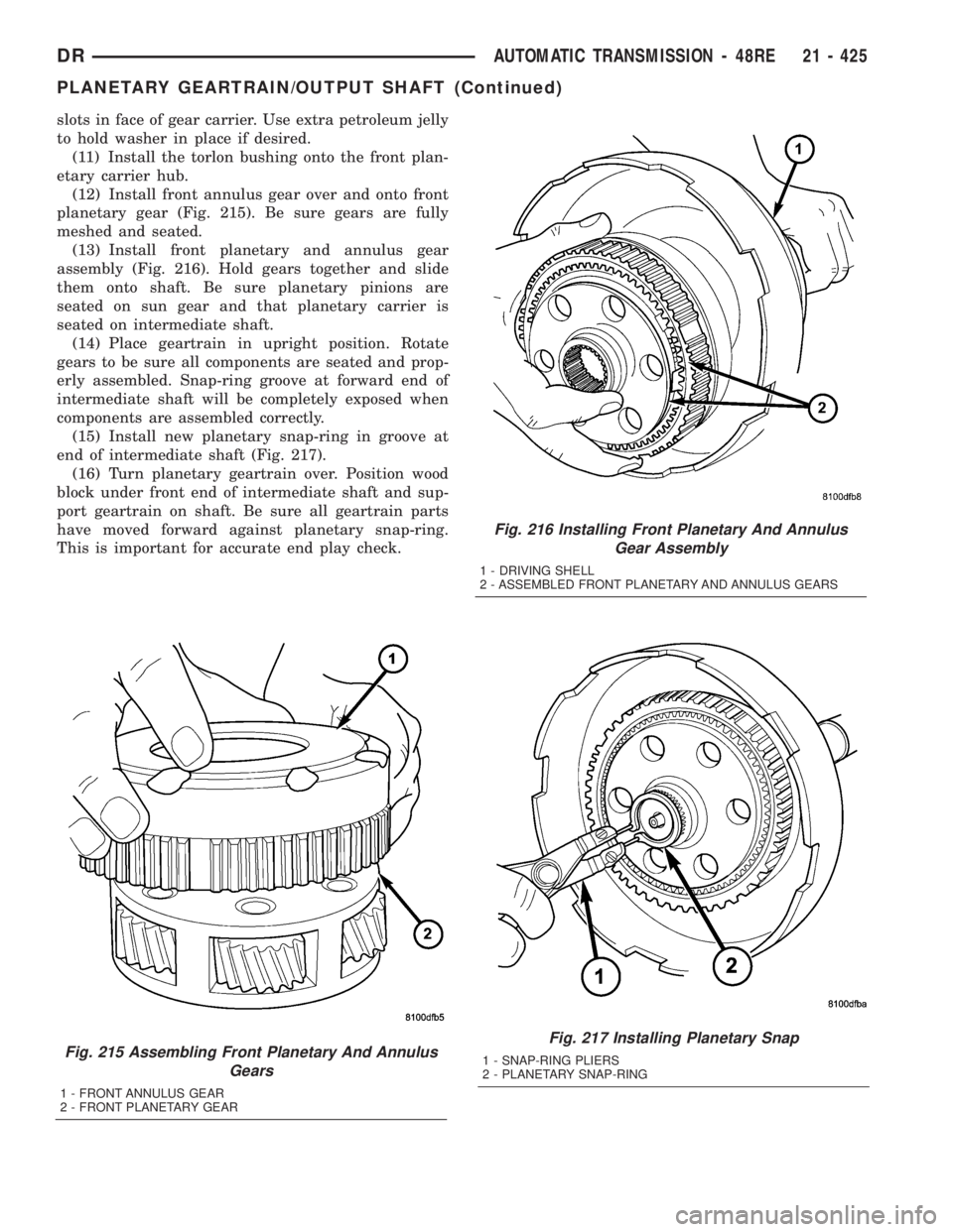
(12) Install front annulus gear over and onto front
planetary gear (Fig. 215). Be sure gears are fully
meshed and seated.
(13) Install front planetary and annulus gear
assembly (Fig. 216). Hold gears together and slide
them onto shaft. Be sure planetary pinions are
seated on sun gear and that planetary carrier is
seated on intermediate shaft.
(14) Place geartrain in upright position. Rotate
gears to be sure all components are seated and prop-
erly assembled. Snap-ring groove at forward end of
intermediate shaft will be completely exposed when
components are assembled correctly.
(15) Install new planetary snap-ring in groove at
end of intermediate shaft (Fig. 217).
(16) Turn planetary geartrain over. Position wood
block under front end of intermediate shaft and sup-
port geartrain on shaft. Be sure all geartrain parts
have moved forward against planetary snap-ring.
This is important for accurate end play check.
Fig. 215 Assembling Front Planetary And Annulus
Gears
1 - FRONT ANNULUS GEAR
2 - FRONT PLANETARY GEAR
Fig. 216 Installing Front Planetary And Annulus
Gear Assembly
1 - DRIVING SHELL
2 - ASSEMBLED FRONT PLANETARY AND ANNULUS GEARS
Fig. 217 Installing Planetary Snap
1 - SNAP-RING PLIERS
2 - PLANETARY SNAP-RING
DRAUTOMATIC TRANSMISSION - 48RE 21 - 425
PLANETARY GEARTRAIN/OUTPUT SHAFT (Continued)
Page 2266 of 2895
OPERATION
To apply the clutch, pressure is applied between
the clutch retainer and piston. The fluid pressure is
provided by the oil pump, transferred through the
control valves and passageways, and enters the
clutch through the hub of the reaction shaft support.
With pressure applied between the clutch retainer
and piston, the piston moves away from the clutch
retainer and compresses the clutch pack. This action
applies the clutch pack, allowing torque to flow
through the input shaft into the driving discs, and
into the clutch plates and pressure plate that are
lugged to the clutch retainer. The waved spring is
used to cushion the application of the clutch pack.
The snap-ring is selective and used to adjust clutch
pack clearance.
When pressure is released from the piston, the
spring returns the piston to its fully released position
and disengages the clutch. The release spring also
helps to cushion the application of the clutch assem-
bly. When the clutch is in the process of being
released by the release spring, fluid flows through a
vent and one-way ball-check-valve located in the pis-
ton. The check-valve is needed to eliminate the pos-sibility of plate drag caused by centrifugal force
acting on the residual fluid trapped in the clutch pis-
ton retainer.
DISASSEMBLY
(1) Remove fiber thrust washer from forward side
of clutch retainer.
(2) Remove input shaft front and rear seal rings.
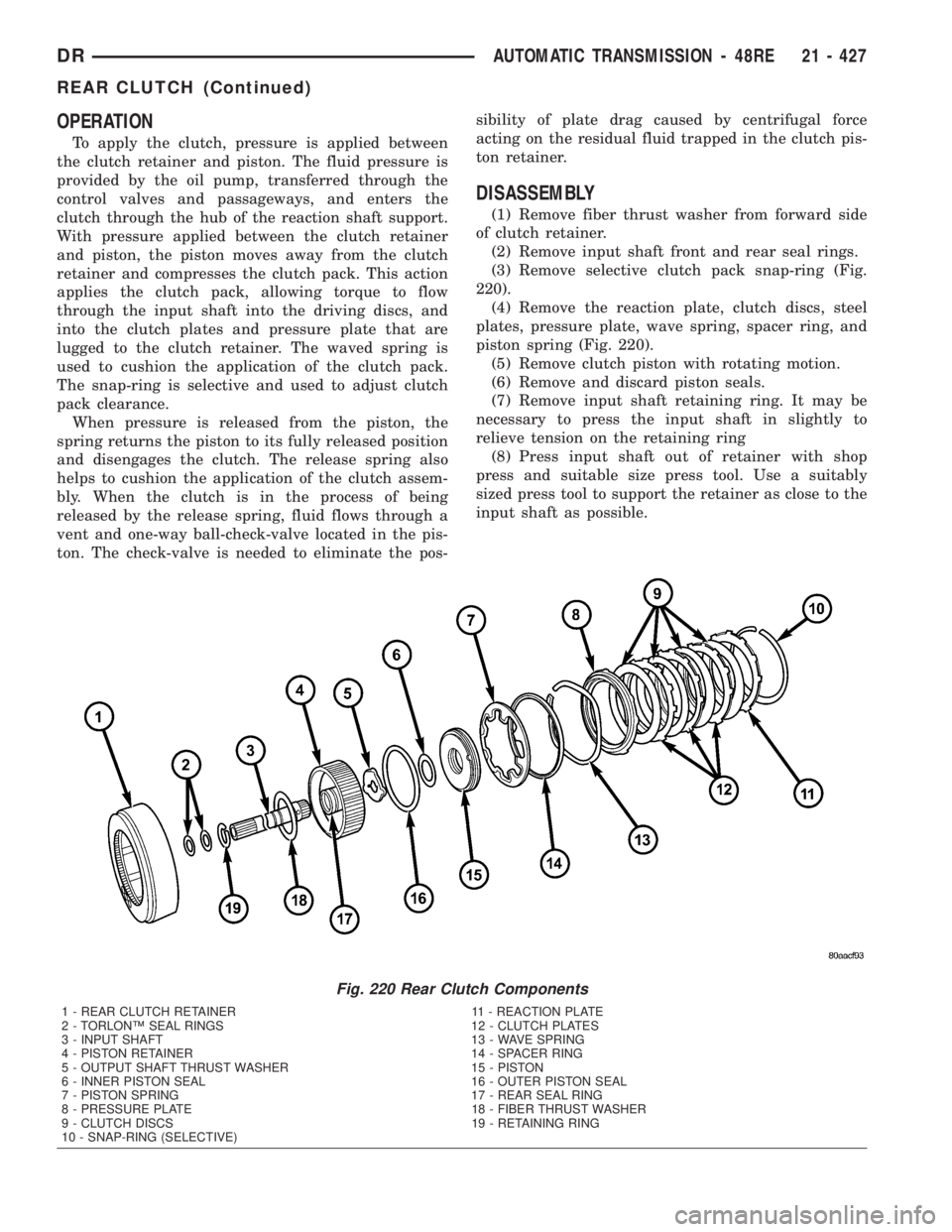
(3) Remove selective clutch pack snap-ring (Fig.
220).
(4) Remove the reaction plate, clutch discs, steel
plates, pressure plate, wave spring, spacer ring, and
piston spring (Fig. 220).
(5) Remove clutch piston with rotating motion.
(6) Remove and discard piston seals.
(7) Remove input shaft retaining ring. It may be
necessary to press the input shaft in slightly to
relieve tension on the retaining ring
(8) Press input shaft out of retainer with shop
press and suitable size press tool. Use a suitably
sized press tool to support the retainer as close to the
input shaft as possible.
Fig. 220 Rear Clutch Components
1 - REAR CLUTCH RETAINER 11 - REACTION PLATE
2 - TORLONŸ SEAL RINGS 12 - CLUTCH PLATES
3 - INPUT SHAFT 13 - WAVE SPRING
4 - PISTON RETAINER 14 - SPACER RING
5 - OUTPUT SHAFT THRUST WASHER 15 - PISTON
6 - INNER PISTON SEAL 16 - OUTER PISTON SEAL
7 - PISTON SPRING 17 - REAR SEAL RING
8 - PRESSURE PLATE 18 - FIBER THRUST WASHER
9 - CLUTCH DISCS 19 - RETAINING RING
10 - SNAP-RING (SELECTIVE)
DRAUTOMATIC TRANSMISSION - 48RE 21 - 427
REAR CLUTCH (Continued)
Page 2267 of 2895
CLEANING
Clean the clutch components with solvent and dry
them with compressed air. Do not use rags or shop
towels to dry any of the clutch parts. Lint from such
materials will adhere to component surfaces and
could restrict or block fluid passages after assembly.
INSPECTION
Replace the clutch discs if warped, worn, scored,
burned/charred, the lugs are damaged, or if the fac-
ing is flaking off. Replace the top and bottom pres-
sure plates if scored, warped, or cracked. Be sure the
driving lugs on the pressure and clutch plates are
also in good condition. The lugs must not be bent,
cracked or damaged in any way.
Replace the piston spring and wave spring if either
part is distorted, warped or broken.
Check the lug grooves in the clutch retainer. The
clutch and pressure plates should slide freely in the
slots. Replace the retainer if the grooves are worn or
damaged. Also check action of the check balls in the
retainer and piston. Each check ball must move
freely and not stick.
Replace the retainer bushing if worn, scored, or
doubt exists about bushing condition.
Inspect the piston and retainer seal surfaces for
nicks or scratches. Minor scratches can be removed
with crocus cloth. However, replace the piston and/or
retainer if the seal surfaces are seriously scored.
Check condition of the fiber thrust washer and
metal output shaft thrust washer. Replace either
washer if worn or damaged.
Check condition of the seal rings on the input shaft
and clutch retainer hub. Replace the seal rings only
if worn, distorted, or damaged. The input shaft front
seal ring is teflon with chamfered ends. The rear ring
is metal with interlocking ends.
Check the input shaft for wear, or damage. Replace
the shaft if worn, scored or damaged in any way.
ASSEMBLY
(1) Soak clutch discs in transmission fluid while
assembling other clutch parts.
(2) Install new seal rings on clutch retainer hub
and input shaft if necessary.
(a) Be sure clutch hub seal ring is fully seated in
groove and is not twisted.
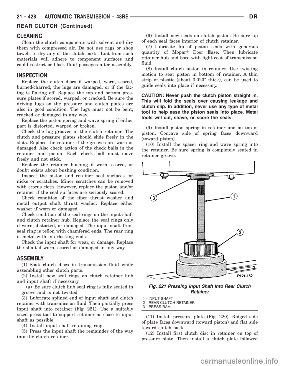
(3) Lubricate splined end of input shaft and clutch
retainer with transmission fluid. Then partially press
input shaft into retainer (Fig. 221). Use a suitably
sized press tool to support retainer as close to input
shaft as possible.
(4) Install input shaft retaining ring.
(5) Press the input shaft the remainder of the way
into the clutch retainer.(6) Install new seals on clutch piston. Be sure lip
of each seal faces interior of clutch retainer.
(7) Lubricate lip of piston seals with generous
quantity of MopartDoor Ease. Then lubricate
retainer hub and bore with light coat of transmission
fluid.
(8) Install clutch piston in retainer. Use twisting
motion to seat piston in bottom of retainer. A thin
strip of plastic (about 0.0209thick), can be used to
guide seals into place if necessary.
CAUTION: Never push the clutch piston straight in.
This will fold the seals over causing leakage and
clutch slip. In addition, never use any type of metal
tool to help ease the piston seals into place. Metal
tools will cut, shave, or score the seals.
(9) Install piston spring in retainer and on top of
piston. Concave side of spring faces downward
(toward piston).
(10) Install the spacer ring and wave spring into
the retainer. Be sure spring is completely seated in
retainer groove.
(11) Install pressure plate (Fig. 220). Ridged side
of plate faces downward (toward piston) and flat side
toward clutch pack.
(12) Install first clutch disc in retainer on top of
pressure plate. Then install a clutch plate followed
Fig. 221 Pressing Input Shaft Into Rear Clutch
Retainer
1 - INPUT SHAFT
2 - REAR CLUTCH RETAINER
3 - PRESS RAM
21 - 428 AUTOMATIC TRANSMISSION - 48REDR
REAR CLUTCH (Continued)
Page 2273 of 2895
in an incorrect T.V. cable adjustment.Slide the
sheath of the T.V. cable (D) back and forth until the
centerlines of the T.V. cable end (B) and the throttle
bell crank lever (C) are aligned within one millimeter
(1mm) (Fig. 232).
(7) While holding the T.V. cable in the set position
push the T.V. cable lock (A) into the down position
(Fig. 232). This will lock the present T.V. cable
adjustment.
NOTE: Be sure that as the cable is pulled forward
and centered on the throttle lever stud, the cable
housing moves smoothly with the cable. Due to the
angle at which the cable housing enters the spring
housing, the cable housing may bind slightly and
create an incorrect adjustment.
(8) Reconnect the T.V. cable (B) to the throttle
bellcrank lever (C).
(9) Check cable adjustment. Verify transmission
throttle lever and lever on throttle body move simul-
taneously.
TORQUE CONVERTER
DESCRIPTION
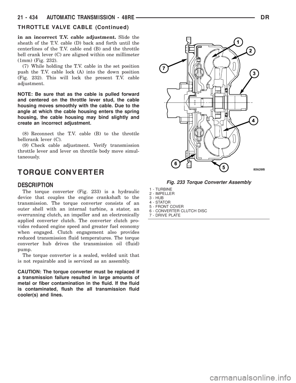
The torque converter (Fig. 233) is a hydraulic
device that couples the engine crankshaft to the
transmission. The torque converter consists of an
outer shell with an internal turbine, a stator, an
overrunning clutch, an impeller and an electronically
applied converter clutch. The converter clutch pro-
vides reduced engine speed and greater fuel economy
when engaged. Clutch engagement also provides
reduced transmission fluid temperatures. The torque
converter hub drives the transmission oil (fluid)
pump.
The torque converter is a sealed, welded unit that
is not repairable and is serviced as an assembly.
CAUTION: The torque converter must be replaced if
a transmission failure resulted in large amounts of
metal or fiber contamination in the fluid. If the fluid
is contaminated, flush the all transmission fluid
cooler(s) and lines.
Fig. 233 Torque Converter Assembly
1 - TURBINE
2 - IMPELLER
3 - HUB
4-STATOR
5 - FRONT COVER
6 - CONVERTER CLUTCH DISC
7 - DRIVE PLATE
21 - 434 AUTOMATIC TRANSMISSION - 48REDR
THROTTLE VALVE CABLE (Continued)
Page 2334 of 2895
NOTE: The air supply which is used must be free of
moisture and dirt. Use a pressure of 30 psi to test
clutch operation.
Apply air pressure at each port. If the clutch is
functioning, a soft thump will be heard as the clutch
is applied. The clutch application can also be felt by
touching the appropriate element while applying air
pressure. As the air pressure is released, the clutch
should also release.
DIAGNOSIS AND TESTING - CONVERTER
HOUSING FLUID LEAK
When diagnosing converter housing fluid leaks,
two items must be established before repair.
(1) Verify that a leak condition actually exists.
(2) Determined the true source of the leak.
Some suspected converter housing fluid leaks may not
be leaks at all. They may only be the result of residual
fluid in the converter housing, or excess fluid spilled dur-
ing factory fill or fill after repair. Converter housing
leaks have several potential sources. Through careful
observation, a leak source can be identified before remov-
ing the transmission for repair. Torque converter seal
leaks tend to move along the drive hub and onto the rear
of the converter. Pump cover seal tend to run down the
cover and the inside surface of the bellhousing.
Some leaks, or suspected leaks, may be particu-
larly difficult to locate. If necessary, a Mopart
approved dye may be used to locate a leak.
TORQUE CONVERTER LEAK POINTS
Possible sources of converter leaks are:
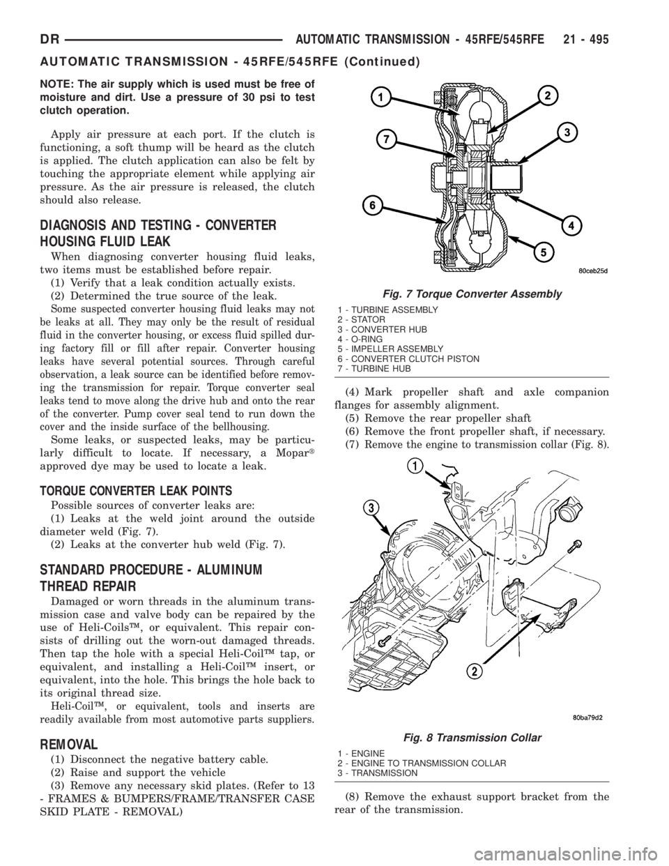
(1) Leaks at the weld joint around the outside
diameter weld (Fig. 7).
(2) Leaks at the converter hub weld (Fig. 7).
STANDARD PROCEDURE - ALUMINUM
THREAD REPAIR
Damaged or worn threads in the aluminum trans-
mission case and valve body can be repaired by the
use of Heli-CoilsŸ, or equivalent. This repair con-
sists of drilling out the worn-out damaged threads.
Then tap the hole with a special Heli-CoilŸ tap, or
equivalent, and installing a Heli-CoilŸ insert, or
equivalent, into the hole. This brings the hole back to
its original thread size.
Heli-CoilŸ, or equivalent, tools and inserts are
readily available from most automotive parts suppliers.
REMOVAL
(1) Disconnect the negative battery cable.
(2) Raise and support the vehicle
(3) Remove any necessary skid plates. (Refer to 13
- FRAMES & BUMPERS/FRAME/TRANSFER CASE
SKID PLATE - REMOVAL)(4) Mark propeller shaft and axle companion
flanges for assembly alignment.
(5) Remove the rear propeller shaft
(6) Remove the front propeller shaft, if necessary.
(7)
Remove the engine to transmission collar (Fig. 8).
(8) Remove the exhaust support bracket from the
rear of the transmission.
Fig. 7 Torque Converter Assembly
1 - TURBINE ASSEMBLY
2-STATOR
3 - CONVERTER HUB
4 - O-RING
5 - IMPELLER ASSEMBLY
6 - CONVERTER CLUTCH PISTON
7 - TURBINE HUB
Fig. 8 Transmission Collar
1 - ENGINE
2 - ENGINE TO TRANSMISSION COLLAR
3 - TRANSMISSION
DRAUTOMATIC TRANSMISSION - 45RFE/545RFE 21 - 495
AUTOMATIC TRANSMISSION - 45RFE/545RFE (Continued)
Page 2438 of 2895
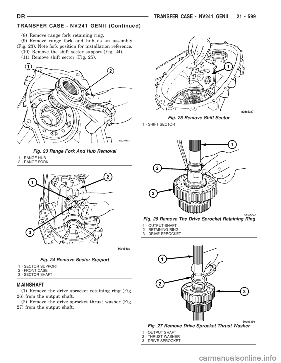
(8) Remove range fork retaining ring.
(9) Remove range fork and hub as an assembly
(Fig. 23). Note fork position for installation reference.
(10) Remove the shift sector support (Fig. 24).
(11) Remove shift sector (Fig. 25).
MAINSHAFT
(1) Remove the drive sprocket retaining ring (Fig.
26) from the output shaft.
(2) Remove the drive sprocket thrust washer (Fig.
27) from the output shaft.
Fig. 23 Range Fork And Hub Removal
1 - RANGE HUB
2 - RANGE FORK
Fig. 24 Remove Sector Support
1 - SECTOR SUPPORT
2 - FRONT CASE
3 - SECTOR SHAFT
Fig. 25 Remove Shift Sector
1 - SHIFT SECTOR
Fig. 26 Remove The Drive Sprocket Retaining Ring
1 - OUTPUT SHAFT
2 - RETAINING RING
3 - DRIVE SPROCKET
Fig. 27 Remove Drive Sprocket Thrust Washer
1 - OUTPUT SHAFT
2 - THRUST WASHER
3 - DRIVE SPROCKET
DRTRANSFER CASE - NV241 GENII 21 - 599
TRANSFER CASE - NV241 GENII (Continued)
Page 2441 of 2895
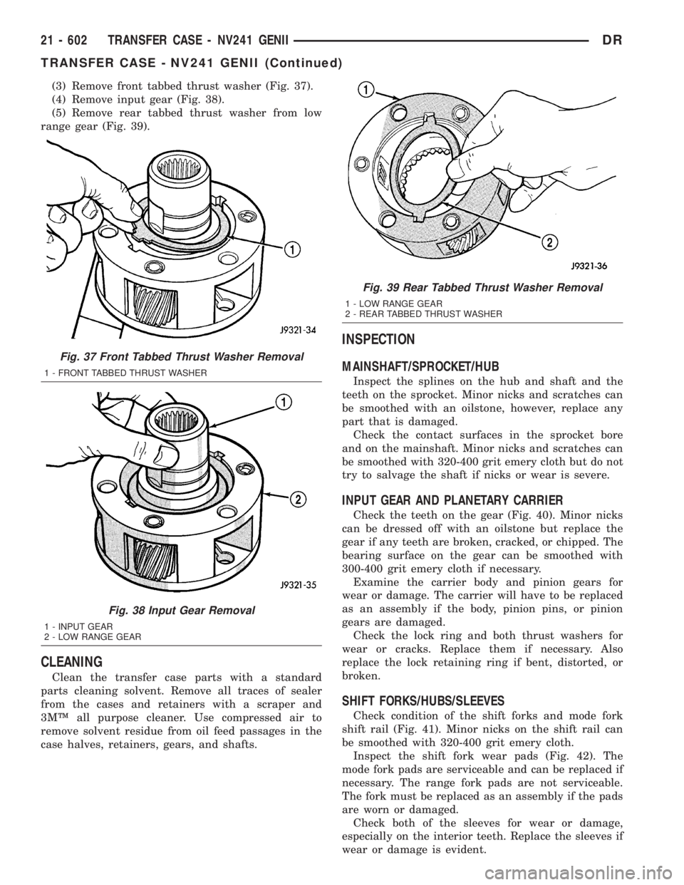
(3) Remove front tabbed thrust washer (Fig. 37).
(4) Remove input gear (Fig. 38).
(5) Remove rear tabbed thrust washer from low
range gear (Fig. 39).
CLEANING
Clean the transfer case parts with a standard
parts cleaning solvent. Remove all traces of sealer
from the cases and retainers with a scraper and
3MŸ all purpose cleaner. Use compressed air to
remove solvent residue from oil feed passages in the
case halves, retainers, gears, and shafts.
INSPECTION
MAINSHAFT/SPROCKET/HUB
Inspect the splines on the hub and shaft and the
teeth on the sprocket. Minor nicks and scratches can
be smoothed with an oilstone, however, replace any
part that is damaged.
Check the contact surfaces in the sprocket bore
and on the mainshaft. Minor nicks and scratches can
be smoothed with 320-400 grit emery cloth but do not
try to salvage the shaft if nicks or wear is severe.
INPUT GEAR AND PLANETARY CARRIER
Check the teeth on the gear (Fig. 40). Minor nicks
can be dressed off with an oilstone but replace the
gear if any teeth are broken, cracked, or chipped. The
bearing surface on the gear can be smoothed with
300-400 grit emery cloth if necessary.
Examine the carrier body and pinion gears for
wear or damage. The carrier will have to be replaced
as an assembly if the body, pinion pins, or pinion
gears are damaged.
Check the lock ring and both thrust washers for
wear or cracks. Replace them if necessary. Also
replace the lock retaining ring if bent, distorted, or
broken.
SHIFT FORKS/HUBS/SLEEVES
Check condition of the shift forks and mode fork
shift rail (Fig. 41). Minor nicks on the shift rail can
be smoothed with 320-400 grit emery cloth.
Inspect the shift fork wear pads (Fig. 42). The
mode fork pads are serviceable and can be replaced if
necessary. The range fork pads are not serviceable.
The fork must be replaced as an assembly if the pads
are worn or damaged.
Check both of the sleeves for wear or damage,
especially on the interior teeth. Replace the sleeves if
wear or damage is evident.
Fig. 37 Front Tabbed Thrust Washer Removal
1 - FRONT TABBED THRUST WASHER
Fig. 38 Input Gear Removal
1 - INPUT GEAR
2 - LOW RANGE GEAR
Fig. 39 Rear Tabbed Thrust Washer Removal
1 - LOW RANGE GEAR
2 - REAR TABBED THRUST WASHER
21 - 602 TRANSFER CASE - NV241 GENIIDR
TRANSFER CASE - NV241 GENII (Continued)
Page 2446 of 2895
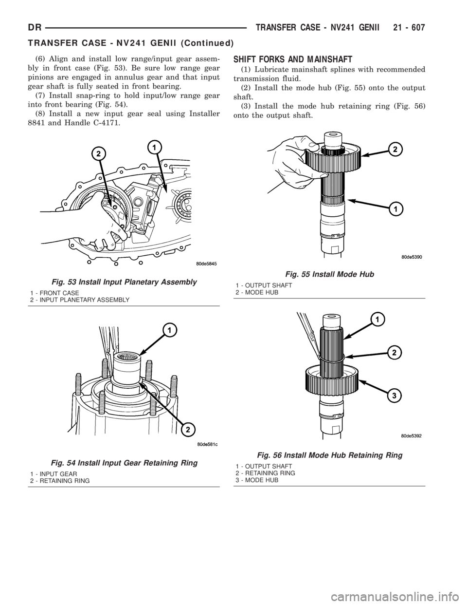
(6) Align and install low range/input gear assem-
bly in front case (Fig. 53). Be sure low range gear
pinions are engaged in annulus gear and that input
gear shaft is fully seated in front bearing.
(7) Install snap-ring to hold input/low range gear
into front bearing (Fig. 54).
(8) Install a new input gear seal using Installer
8841 and Handle C-4171.SHIFT FORKS AND MAINSHAFT
(1) Lubricate mainshaft splines with recommended
transmission fluid.
(2) Install the mode hub (Fig. 55) onto the output
shaft.
(3) Install the mode hub retaining ring (Fig. 56)
onto the output shaft.
Fig. 53 Install Input Planetary Assembly
1 - FRONT CASE
2 - INPUT PLANETARY ASSEMBLY
Fig. 54 Install Input Gear Retaining Ring
1 - INPUT GEAR
2 - RETAINING RING
Fig. 55 Install Mode Hub
1 - OUTPUT SHAFT
2 - MODE HUB
Fig. 56 Install Mode Hub Retaining Ring
1 - OUTPUT SHAFT
2 - RETAINING RING
3 - MODE HUB
DRTRANSFER CASE - NV241 GENII 21 - 607
TRANSFER CASE - NV241 GENII (Continued)