2003 DODGE RAM seat adjustment
[x] Cancel search: seat adjustmentPage 81 of 2895
INSTALLATION
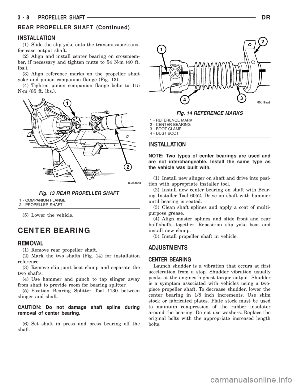
(1) Slide the slip yoke onto the transmission/trans-
fer case output shaft.
(2) Align and install center bearing on crossmem-
ber, if necessary and tighten nutts to 54 N´m (40 ft.
lbs.).
(3) Align reference marks on the propeller shaft
yoke and pinion companion flange (Fig. 13).
(4) Tighten pinion companion flange bolts to 115
N´m (85 ft. lbs.).
(5) Lower the vehicle.
CENTER BEARING
REMOVAL
(1) Remove rear propeller shaft.
(2) Mark the two shafts (Fig. 14) for installation
reference.
(3) Remove slip joint boot clamp and separate the
two shafts.
(4) Use hammer and punch to tap slinger away
from shaft to provide room for bearing splitter.
(5) Position Bearing Splitter Tool 1130 between
slinger and shaft.
CAUTION: Do not damage shaft spline during
removal of center bearing.
(6) Set shaft in press and press bearing off the
shaft.
INSTALLATION
NOTE: Two types of center bearings are used and
are not interchangeable. Install the same type as
the vehicle was built with.
(1) Install new slinger on shaft and drive into posi-
tion with appropriate installer tool.
(2) Install new center bearing on shaft with Bear-
ing Installer Tool 6052. Drive on shaft with hammer
until bearing is seated.
(3) Clean shaft splines and apply a coat of multi-
purpose grease.
(4) Align master splines and slide front and rear
half-shafts together. Reposition slip yoke boot and
install new clamp.
(5) Install propeller shaft in vehicle.
ADJUSTMENTS
CENTER BEARING
Launch shudder is a vibration that occurs at first
acceleration from a stop. Shudder vibration usually
peaks at the engines highest torque output. Shudder
is a symptom associated with vehicles using a two-
piece propeller shaft. To decrease shudder, lower the
center bearing in 1/8 inch increments. Use shim
stock or fabricated plates. Plate stock must be used
to maintain compression of the rubber insulator
around the bearing. Do not use washers. Replace the
original bolts with the appropriate increased length
bolts.
Fig. 13 REAR PROPELLER SHAFT
1 - COMPANION FLANGE
2 - PROPELLER SHAFT
Fig. 14 REFERENCE MARKS
1 - REFERENCE MARK
2 - CENTER BEARING
3 - BOOT CLAMP
4 - DUST BOOT
3 - 8 PROPELLER SHAFTDR
REAR PROPELLER SHAFT (Continued)
Page 137 of 2895

(7) Back off the ring gear side adjuster 4 holes, to
obtain initial ring gear backlash.
(8) Install ring gear side adjuster lock and bolt. Do
not tighten adjuster lock bolt at this time.
(9) Tighten pinion gear side adjuster firmly
against the differential case bearing cup.
(10) Rotate the pinion several times to seat the dif-
ferential bearings.
(11) Loosen pinion gear side adjuster until it is no
longer in contact with the bearing cup.
(12) Tighten pinion gear side adjuster until it just
makes contact with the bearing cup.
(13) Tighten pinion gear side adjuster an addi-
tional:
²New Bearings:6 Adjuster Holes
²Original Bearings:4 Adjuster Holes
(14) Install pinion gear side adjuster lock and bolt.
Do not tighten adjuster lock bolt at this time.
(15) Tighten bearing cap bolts to 85 N´m (63 ft.
lbs.).
(16) Tighten adjuster lock bolts to 25 N´m (18 ft.
lbs.) (Fig. 39).(17) Measure ring gear backlash and check gear
tooth contact pattern. Refer to Adjustments for pro-
cedure.
(18) Install axle shafts and hub bearings.
(19) Install differential housing gasket and cover.
Tighten cover bolts to 40 N´m (30 ft. lbs.).
(20) Fill differential with lubricant, refer to Lubri-
cation & Maintenance for capacity and lubricant
type.
(21) Install fill plug and tighten to 32 N´m (24 ft.
lbs.).
DIFFERENTIAL CASE
BEARINGS
REMOVAL
(1) Remove the differential case from the housing.
(2) Install Plug 8888 into the end of the case.
(3) Remove differental case bearings with Bearing
Splitter 1130 and Bridge 938 (Fig. 40).
Fig. 39 ADJUSTER LOCK BOLT
1 - DIFFERENTIAL CASE
2 - ADJUSTER LOCK
3 - ADJUSTER LOCK BOLT
4 - BEARING CAP BOLT
Fig. 40 DIFFERENTIAL CASE BEARING
1 - BRIDGE
2 - SPLITTER
3 - BEARING
4 - PLUG
3 - 64 FRONT AXLE - 9 1/4 AADR
DIFFERENTIAL (Continued)
Page 149 of 2895
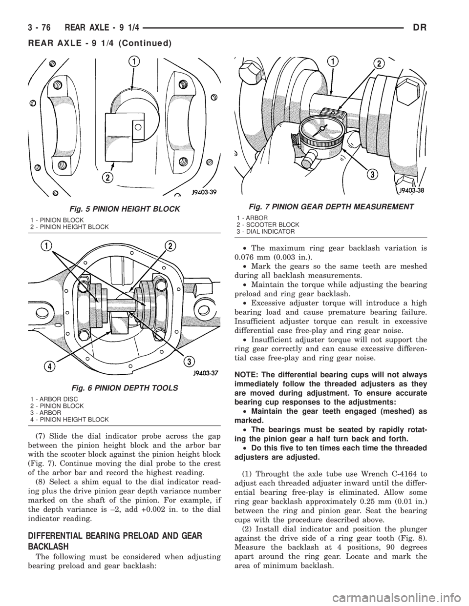
(7) Slide the dial indicator probe across the gap
between the pinion height block and the arbor bar
with the scooter block against the pinion height block
(Fig. 7). Continue moving the dial probe to the crest
of the arbor bar and record the highest reading.
(8) Select a shim equal to the dial indicator read-
ing plus the drive pinion gear depth variance number
marked on the shaft of the pinion. For example, if
the depth variance is ±2, add +0.002 in. to the dial
indicator reading.
DIFFERENTIAL BEARING PRELOAD AND GEAR
BACKLASH
The following must be considered when adjusting
bearing preload and gear backlash:²The maximum ring gear backlash variation is
0.076 mm (0.003 in.).
²Mark the gears so the same teeth are meshed
during all backlash measurements.
²Maintain the torque while adjusting the bearing
preload and ring gear backlash.
²Excessive adjuster torque will introduce a high
bearing load and cause premature bearing failure.
Insufficient adjuster torque can result in excessive
differential case free-play and ring gear noise.
²Insufficient adjuster torque will not support the
ring gear correctly and can cause excessive differen-
tial case free-play and ring gear noise.
NOTE: The differential bearing cups will not always
immediately follow the threaded adjusters as they
are moved during adjustment. To ensure accurate
bearing cup responses to the adjustments:
²Maintain the gear teeth engaged (meshed) as
marked.
²The bearings must be seated by rapidly rotat-
ing the pinion gear a half turn back and forth.
²Do this five to ten times each time the threaded
adjusters are adjusted.
(1) Throught the axle tube use Wrench C-4164 to
adjust each threaded adjuster inward until the differ-
ential bearing free-play is eliminated. Allow some
ring gear backlash approximately 0.25 mm (0.01 in.)
between the ring and pinion gear. Seat the bearing
cups with the procedure described above.
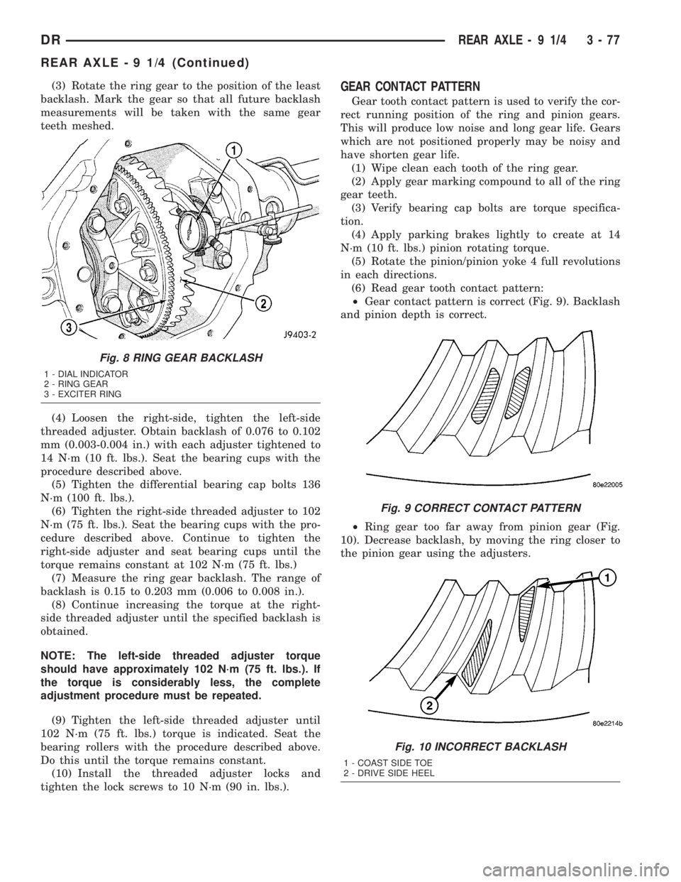
(2) Install dial indicator and position the plunger
against the drive side of a ring gear tooth (Fig. 8).
Measure the backlash at 4 positions, 90 degrees
apart around the ring gear. Locate and mark the
area of minimum backlash.
Fig. 5 PINION HEIGHT BLOCK
1 - PINION BLOCK
2 - PINION HEIGHT BLOCK
Fig. 6 PINION DEPTH TOOLS
1 - ARBOR DISC
2 - PINION BLOCK
3 - ARBOR
4 - PINION HEIGHT BLOCK
Fig. 7 PINION GEAR DEPTH MEASUREMENT
1 - ARBOR
2 - SCOOTER BLOCK
3 - DIAL INDICATOR
3 - 76 REAR AXLE-91/4DR
REAR AXLE - 9 1/4 (Continued)
Page 150 of 2895
(3) Rotate the ring gear to the position of the least
backlash. Mark the gear so that all future backlash
measurements will be taken with the same gear
teeth meshed.
(4) Loosen the right-side, tighten the left-side
threaded adjuster. Obtain backlash of 0.076 to 0.102
mm (0.003-0.004 in.) with each adjuster tightened to
14 N´m (10 ft. lbs.). Seat the bearing cups with the
procedure described above.
(5) Tighten the differential bearing cap bolts 136
N´m (100 ft. lbs.).
(6) Tighten the right-side threaded adjuster to 102
N´m (75 ft. lbs.). Seat the bearing cups with the pro-
cedure described above. Continue to tighten the
right-side adjuster and seat bearing cups until the
torque remains constant at 102 N´m (75 ft. lbs.)
(7) Measure the ring gear backlash. The range of
backlash is 0.15 to 0.203 mm (0.006 to 0.008 in.).
(8) Continue increasing the torque at the right-
side threaded adjuster until the specified backlash is
obtained.
NOTE: The left-side threaded adjuster torque
should have approximately 102 N´m (75 ft. lbs.). If
the torque is considerably less, the complete
adjustment procedure must be repeated.
(9) Tighten the left-side threaded adjuster until
102 N´m (75 ft. lbs.) torque is indicated. Seat the
bearing rollers with the procedure described above.
Do this until the torque remains constant.
(10) Install the threaded adjuster locks and
tighten the lock screws to 10 N´m (90 in. lbs.).GEAR CONTACT PATTERN
Gear tooth contact pattern is used to verify the cor-
rect running position of the ring and pinion gears.
This will produce low noise and long gear life. Gears
which are not positioned properly may be noisy and
have shorten gear life.
(1) Wipe clean each tooth of the ring gear.
(2) Apply gear marking compound to all of the ring
gear teeth.
(3) Verify bearing cap bolts are torque specifica-
tion.
(4) Apply parking brakes lightly to create at 14
N´m (10 ft. lbs.) pinion rotating torque.
(5) Rotate the pinion/pinion yoke 4 full revolutions
in each directions.
(6) Read gear tooth contact pattern:
²Gear contact pattern is correct (Fig. 9). Backlash
and pinion depth is correct.
²Ring gear too far away from pinion gear (Fig.
10). Decrease backlash, by moving the ring closer to
the pinion gear using the adjusters.
Fig. 8 RING GEAR BACKLASH
1 - DIAL INDICATOR
2 - RING GEAR
3 - EXCITER RING
Fig. 9 CORRECT CONTACT PATTERN
Fig. 10 INCORRECT BACKLASH
1 - COAST SIDE TOE
2 - DRIVE SIDE HEEL
DRREAR AXLE - 9 1/4 3 - 77
REAR AXLE - 9 1/4 (Continued)
Page 161 of 2895
DISASSEMBLY
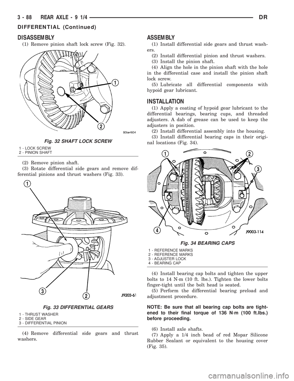
(1) Remove pinion shaft lock screw (Fig. 32).
(2) Remove pinion shaft.
(3) Rotate differential side gears and remove dif-
ferential pinions and thrust washers (Fig. 33).
(4) Remove differential side gears and thrust
washers.
ASSEMBLY
(1) Install differential side gears and thrust wash-
ers.
(2) Install differential pinion and thrust washers.
(3) Install the pinion shaft.
(4) Align the hole in the pinion shaft with the hole
in the differential case and install the pinion shaft
lock screw.
(5) Lubricate all differential components with
hypoid gear lubricant.
INSTALLATION
(1) Apply a coating of hypoid gear lubricant to the
differential bearings, bearing cups, and threaded
adjusters. A dab of grease can be used to keep the
adjusters in position.
(2) Install differential assembly into the housing.
(3) Install differential bearing caps in their origi-
nal locations (Fig. 34).
(4) Install bearing cap bolts and tighten the upper
bolts to 14 N´m (10 ft. lbs.). Tighten the lower bolts
finger-tight until the bolt head is seated.
(5) Perform the differential bearing preload and
adjustment procedure.
NOTE: Be sure that all bearing cap bolts are tight-
ened to their final torque of 136 N´m (100 ft.lbs.)
before proceeding.
(6) Install axle shafts.
(7) Apply a 1/4 inch bead of red Mopar Silicone
Rubber Sealant or equivalent to the housing cover
(Fig. 35).
Fig. 32 SHAFT LOCK SCREW
1 - LOCK SCREW
2 - PINION SHAFT
Fig. 33 DIFFERENTIAL GEARS
1 - THRUST WASHER
2 - SIDE GEAR
3 - DIFFERENTIAL PINION
Fig. 34 BEARING CAPS
1 - REFERENCE MARKS
2 - REFERENCE MARKS
3 - ADJUSTER LOCK
4 - BEARING CAP
3 - 88 REAR AXLE-91/4DR
DIFFERENTIAL (Continued)
Page 178 of 2895
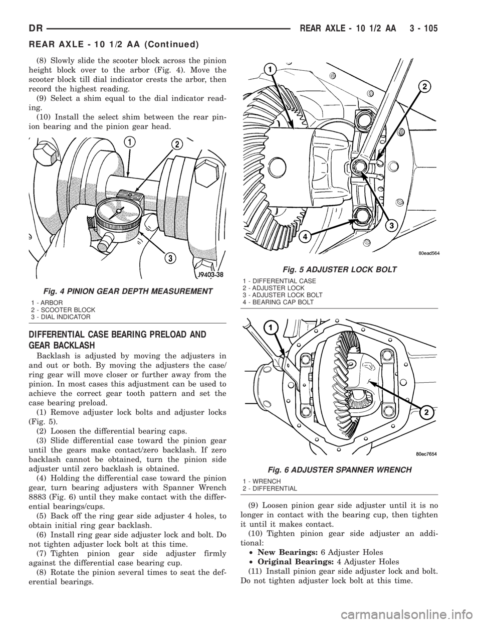
(8) Slowly slide the scooter block across the pinion
height block over to the arbor (Fig. 4). Move the
scooter block till dial indicator crests the arbor, then
record the highest reading.
(9) Select a shim equal to the dial indicator read-
ing.
(10) Install the select shim between the rear pin-
ion bearing and the pinion gear head.
DIFFERENTIAL CASE BEARING PRELOAD AND
GEAR BACKLASH
Backlash is adjusted by moving the adjusters in
and out or both. By moving the adjusters the case/
ring gear will move closer or further away from the
pinion. In most cases this adjustment can be used to
achieve the correct gear tooth pattern and set the
case bearing preload.
(1) Remove adjuster lock bolts and adjuster locks
(Fig. 5).
(2) Loosen the differential bearing caps.
(3) Slide differential case toward the pinion gear
until the gears make contact/zero backlash. If zero
backlash cannot be obtained, turn the pinion side
adjuster until zero backlash is obtained.
(4) Holding the differential case toward the pinion
gear, turn bearing adjusters with Spanner Wrench
8883 (Fig. 6) until they make contact with the differ-
ential bearings/cups.
(5) Back off the ring gear side adjuster 4 holes, to
obtain initial ring gear backlash.
(6) Install ring gear side adjuster lock and bolt. Do
not tighten adjuster lock bolt at this time.
(7) Tighten pinion gear side adjuster firmly
against the differential case bearing cup.
(8) Rotate the pinion several times to seat the def-
erential bearings.(9) Loosen pinion gear side adjuster until it is no
longer in contact with the bearing cup, then tighten
it until it makes contact.
(10) Tighten pinion gear side adjuster an addi-
tional:
²New Bearings:6 Adjuster Holes
²Original Bearings:4 Adjuster Holes
(11) Install pinion gear side adjuster lock and bolt.
Do not tighten adjuster lock bolt at this time.
Fig. 4 PINION GEAR DEPTH MEASUREMENT
1 - ARBOR
2 - SCOOTER BLOCK
3 - DIAL INDICATOR
Fig. 5 ADJUSTER LOCK BOLT
1 - DIFFERENTIAL CASE
2 - ADJUSTER LOCK
3 - ADJUSTER LOCK BOLT
4 - BEARING CAP BOLT
Fig. 6 ADJUSTER SPANNER WRENCH
1 - WRENCH
2 - DIFFERENTIAL
DRREAR AXLE - 10 1/2 AA 3 - 105
REAR AXLE - 10 1/2 AA (Continued)
Page 191 of 2895

(8) Install ring gear side adjuster lock and bolt. Do
not tighten adjuster lock bolt at this time.
(9) Tighten pinion gear side adjuster firmly
against the differential case bearing cup.
(10) Rotate the pinion several times to seat the dif-
ferential bearings.
(11) Loosen pinion gear side adjuster until it is no
longer in contact with the bearing cup.
(12) Tighten pinion gear side adjuster until it just
makes contact with the bearing cup.
(13) Tighten pinion gear side adjuster an addi-
tional:
²New Bearings6 Adjuster Holes
²Original Bearings4 Adjuster Holes
(14) Install pinion gear side adjuster lock and bolt.
Do not tighten adjuster lock bolt at this time.
(15) Tighten bearing cap bolts to 165 N´m (122 ft.
lbs.).
(16) Tighten adjuster lock bolts to 25 N´m (18 ft.
lbs.) (Fig. 37).
(17) Measure ring gear backlash and check gear
tooth contact pattern. Refer to Adjustments for pro-
cedure.
(18) Install axle shafts.
(19) Install differential housing gasket and cover.
Tighten cover bolts to 40 N´m (30 ft. lbs.).
(20) Fill axle with lubricant, refer to Lubrication &
Maintenance for capacity and lubricant type.
(21) Install fill plug and tighten to 32 N´m (24 ft.
lbs.).DIFFERENTIAL TRAC-RITE
DESCRIPTION
The Trac-RiteŸ differential is a helical gear differ-
ential. The differential has two side gears, six pinion
gears and six pinion brake shoes.
NOTE: The differential is seviced as an assembly
only if damaged, but can be disassembled for
cleaning. The assembly should be cleaned every
time a bearing is changed due to damage.
OPERATION
When one wheel begins to spin the pinion gears on
that side are forced toward the pinion brake shoes.
The pinion brake shoes then cause frictional drag on
the opposite pinion gears and the side gear. These
friction forces transfer the power to the opposite
wheel. Once the frictional forces are overcome, differ-
entiation will occur. The torque will be continually
biased by the frictional forces to the high traction
wheel.
DISASSEMBLY
(1) Remove differential ring gear bolts.
(2) Remove differential case cover locating screws
(Fig. 38).
(3) Remove differential case cover.
(4) Remove side gear and thrust washer (Fig. 39).
Fig. 37 ADJUSTER LOCK BOLT
1 - DIFFERENTIAL CASE
2 - ADJUSTER LOCK
3 - ADJUSTER LOCK BOLT
4 - BEARING CAP BOLT
Fig. 38 LOCATION SCREWS
1 - DIFFERENTIAL COVER
2 - LOCATION SCREWS
3 - 118 REAR AXLE - 10 1/2 AADR
DIFFERENTIAL (Continued)
Page 205 of 2895
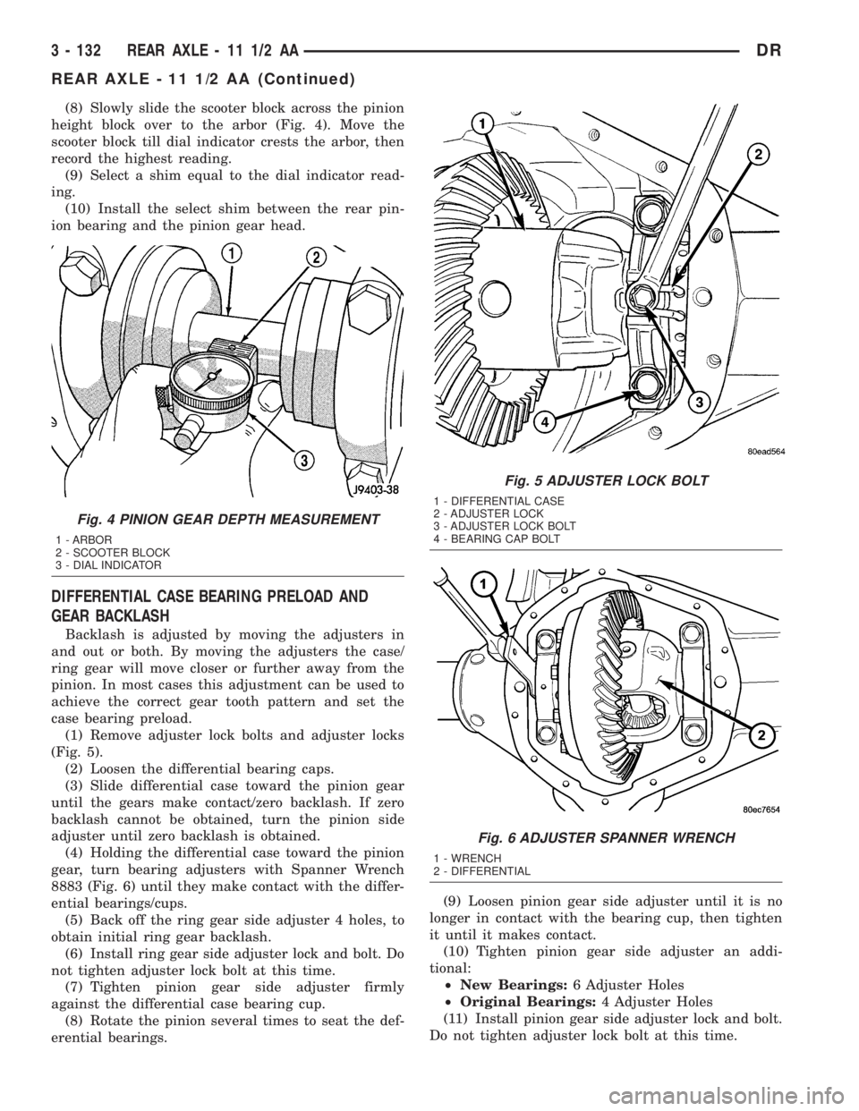
(8) Slowly slide the scooter block across the pinion
height block over to the arbor (Fig. 4). Move the
scooter block till dial indicator crests the arbor, then
record the highest reading.
(9) Select a shim equal to the dial indicator read-
ing.
(10) Install the select shim between the rear pin-
ion bearing and the pinion gear head.
DIFFERENTIAL CASE BEARING PRELOAD AND
GEAR BACKLASH
Backlash is adjusted by moving the adjusters in
and out or both. By moving the adjusters the case/
ring gear will move closer or further away from the
pinion. In most cases this adjustment can be used to
achieve the correct gear tooth pattern and set the
case bearing preload.
(1) Remove adjuster lock bolts and adjuster locks
(Fig. 5).
(2) Loosen the differential bearing caps.
(3) Slide differential case toward the pinion gear
until the gears make contact/zero backlash. If zero
backlash cannot be obtained, turn the pinion side
adjuster until zero backlash is obtained.
(4) Holding the differential case toward the pinion
gear, turn bearing adjusters with Spanner Wrench
8883 (Fig. 6) until they make contact with the differ-
ential bearings/cups.
(5) Back off the ring gear side adjuster 4 holes, to
obtain initial ring gear backlash.
(6) Install ring gear side adjuster lock and bolt. Do
not tighten adjuster lock bolt at this time.
(7) Tighten pinion gear side adjuster firmly
against the differential case bearing cup.
(8) Rotate the pinion several times to seat the def-
erential bearings.(9) Loosen pinion gear side adjuster until it is no
longer in contact with the bearing cup, then tighten
it until it makes contact.
(10) Tighten pinion gear side adjuster an addi-
tional:
²New Bearings:6 Adjuster Holes
²Original Bearings:4 Adjuster Holes
(11) Install pinion gear side adjuster lock and bolt.
Do not tighten adjuster lock bolt at this time.
Fig. 4 PINION GEAR DEPTH MEASUREMENT
1 - ARBOR
2 - SCOOTER BLOCK
3 - DIAL INDICATOR
Fig. 5 ADJUSTER LOCK BOLT
1 - DIFFERENTIAL CASE
2 - ADJUSTER LOCK
3 - ADJUSTER LOCK BOLT
4 - BEARING CAP BOLT
Fig. 6 ADJUSTER SPANNER WRENCH
1 - WRENCH
2 - DIFFERENTIAL
3 - 132 REAR AXLE - 11 1/2 AADR
REAR AXLE - 11 1/2 AA (Continued)