2003 DODGE RAM electrical
[x] Cancel search: electricalPage 1507 of 2895
DISTRIBUTOR BUSHING
REMOVAL
(1) Remove distributor (Refer to 8 - ELECTRICAL/
IGNITION CONTROL/DISTRIBUTOR - REMOVAL).
(2) Remove the intake manifold (Refer to 9 -
ENGINE/MANIFOLDS/INTAKE MANIFOLD -
REMOVAL).
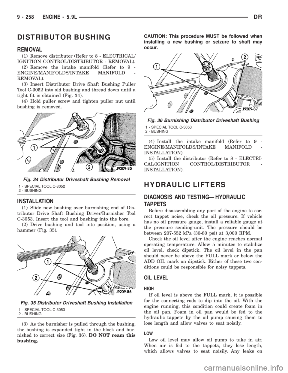
(3) Insert Distributor Drive Shaft Bushing Puller
Tool C-3052 into old bushing and thread down until a
tight fit is obtained (Fig. 34).
(4) Hold puller screw and tighten puller nut until
bushing is removed.
INSTALLATION
(1) Slide new bushing over burnishing end of Dis-
tributor Drive Shaft Bushing Driver/Burnisher Tool
C-3053. Insert the tool and bushing into the bore.
(2) Drive bushing and tool into position, using a
hammer (Fig. 35).
(3) As the burnisher is pulled through the bushing,
the bushing is expanded tight in the block and bur-
nished to correct size (Fig. 36).DO NOT ream this
bushing.CAUTION: This procedure MUST be followed when
installing a new bushing or seizure to shaft may
occur.
(4) Install the intake manifold (Refer to 9 -
ENGINE/MANIFOLDS/INTAKE MANIFOLD -
INSTALLATION).
(5) Install the distributor (Refer to 8 - ELECTRI-
CAL/IGNITION CONTROL/DISTRIBUTOR -
INSTALLATION).
HYDRAULIC LIFTERS
DIAGNOSIS AND TESTINGÐHYDRAULIC
TAPPETS
Before disassembling any part of the engine to cor-
rect tappet noise, check the oil pressure. If vehicle
has no oil pressure gauge, install a reliable gauge at
the pressure sending-unit. The pressure should be
between 207-552 kPa (30-80 psi) at 3,000 RPM.
Check the oil level after the engine reaches normal
operating temperature. Allow 5 minutes to stabilize
oil level, check dipstick. The oil level in the pan
should never be above the FULL mark or below the
ADD OIL mark on dipstick. Either of these two con-
ditions could be responsible for noisy tappets.
OIL LEVEL
HIGH
If oil level is above the FULL mark, it is possible
for the connecting rods to dip into the oil. With the
engine running, this condition could create foam in
the oil pan. Foam in oil pan would be fed to the
hydraulic tappets by the oil pump causing them to
lose length and allow valves to seat noisily.
LOW
Low oil level may allow oil pump to take in air.
When air is fed to the tappets, they lose length,
which allows valves to seat noisily. Any leaks on
Fig. 34 Distributor Driveshaft Bushing Removal
1 - SPECIAL TOOL C-3052
2 - BUSHING
Fig. 35 Distributor Driveshaft Bushing Installation
1 - SPECIAL TOOL C-3053
2 - BUSHING
Fig. 36 Burnishing Distributor Driveshaft Bushing
1 - SPECIAL TOOL C-3053
2 - BUSHING
9 - 258 ENGINE - 5.9LDR
Page 1539 of 2895
²Installing an insert into the tapped hole to bring
the hole back to its original thread size.
STANDARD PROCEDUREÐHYDROSTATIC
LOCK
CAUTION: DO NOT use the starter motor to rotate
the crankshaft. Severe damage could occur.
When an engine is suspected of hydrostatic lock
(regardless of what caused the problem), follow the
steps below.
(1) Disconnect the negative cable(s) from the bat-
tery.
(2) Inspect air cleaner, induction system, and
intake manifold to ensure system is dry and clear of
foreign material.
(3) Place a shop towel around the fuel injectors to
catch any fluid that may possibly be under pressure
in the cylinder head. Remove the fuel injectors (Refer
to 14 - FUEL SYSTEM/FUEL INJECTION/FUEL
INJECTOR - REMOVAL).
(4) With all injectors removed, rotate the crank-
shaft using the crankshaft barring tool (PN 7471±B).
(5) Identify the fluid in the cylinders (coolant, fuel,
oil, etc.).
(6) Be sure all fluid has been removed from the
cylinders.
(7) Repair engine or components as necessary to
prevent this problem from occurring again.
(8) Squirt a small amount of engine oil into the
cylinders to lubricate the walls. This will prevent
damage on restart.
(9) Install fuel injectors (Refer to 14 - FUEL SYS-
TEM/FUEL INJECTION/FUEL INJECTOR -
INSTALLATION).
(10) Drain engine oil. Remove and discard the oil
filter (Refer to 9 - ENGINE/LUBRICATION/OIL FIL-
TER - REMOVAL).
(11) Install the drain plug. Tighten the plug to 50
N´m (37 ft. lbs.) torque.
(12) Install a new oil filter (Refer to 9 - ENGINE/
LUBRICATION/OIL FILTER - INSTALLATION).
(13) Fill engine crankcase with the specified
amount and grade of oil (Refer to LUBRICATION &
MAINTENANCE/FLUID TYPES - SPECIFICA-
TIONS).
(14) Connect the negative cable(s) to the battery.
(15) Start the engine and check for any leaks.
REMOVAL
REMOVALÐENGINE
(1) Disconnect both battery negative cables.
(2) Disconnect engine grid heater harness at grid
heater relays.(3) Disconnect electrical connections from rear of
alternator.
(4) Recover A/C refrigerant. (Refer to 24 - HEAT-
ING & AIR CONDITIONING/PLUMBING - STAN-
DARD PROCEDURE).
(5) Raise vehicle on a hoist.
(6) Drain engine coolant (Refer to 7 - COOLING -
STANDARD PROCEDURE).
(7) Remove engine oil drain plug and drain engine
oil.
(8) Remove fan/drive assembly. Refer to Section 7
± Fan/Drive Removal
(9) Remove radiator upper hose.
(10) Remove upper fan shroud mounting bolts.
(11) Disconnect the coolant recovery bottle hose
from the radiator fill neck and remove bottle.
(12) Using a 36mm wrench, remove viscous fan/
drive assembly. (Refer to 7 - COOLING/ENGINE/RA-
DIATOR FAN - REMOVAL).
(13) Remove cooling fan and shroud together.
(14) Disconnect heater core supply and return
hoses from the cylinder head fitting and coolant pipe.
(15) Raise vehicle on a hoist.
(16) Remove transmission and transfer case (if
equipped).
(17) Disconnect exhaust pipe from turbocharger
extension pipe.
(18) Disconnect engine harness to vehicle harness
connectors.
(19) Remove starter motor (Refer to 8 - ELECTRI-
CAL/STARTING/STARTER MOTOR - REMOVAL).
(20) Remove flywheel/flexplate.
(21) Remove transmission adapter
(22) Disconnect A/C suction/discharge hose from
the rear of the A/C compressor.
(23) Lower vehicle.
(24) Disconnect lower radiator hose from radiator
outlet.
(25) Automatic transmission models:
(26) Disconnect transmission oil cooler lines from
in front of radiator using special tool #6931
(27) Remove radiator. (Refer to 7 - COOLING/EN-
GINE/RADIATOR - REMOVAL).
(28) If A/C equipped, disconnect A/C condenser
refrigerant lines.
(29) Disconnect charge air cooler piping.
(30) Remove charge air cooler mounting bolts.
(31) Remove charge air cooler (and A/C condenser
if equipped) from vehicle.
(32) Remove damper and speed indicator ring from
front of engine.
(33) Disconnect engine block heater connector.
(34) Disconnect A/C compressor and pressure sen-
sor electrical connectors.
9 - 290 ENGINE 5.9L DIESELDR
ENGINE 5.9L DIESEL (Continued)
Page 1541 of 2895
(2) Lower engine into the engine compartment and
install the engine the engine mount through bolts
and nuts.
(3) Tighten the mount through bolts and nuts to
88 N-m (65 ft-lbs) torque.
(4) Remove the engine lifting device (Tool 9009).
(5) Check cylinder head capscrew length and
install into cylinder head.
(6) Torque alternately to 70 N-m (52 ft-lbs). Torque
alternately to 105 N-m (77 ft-lbs). Rotate 90 degrees.
(7) Install rocker housing. Torque to 24 N-m (18 ft-
lbs). Refer to Section 9 Rocker Housing Installation
(8) Replace injector o-ring and sealing washer on
injectors #5 and #6. Install injectors and alternately
tighten hold-down capscrews to 10 N-m (89 in-lbs).
(9) Install fuel connector tube and fuel connector
tube nut. Torque to 50 N-m (37 ft-lb). 10.
(10) Install #5 and #6 high pressure fuel lines. Fol-
low correct torque sequence per section 14. Torque
fuel line fittings to 30 N-m (22 ft-lb). Torque brace
capscrew to 24 N-m (18 ft-lb).
(11) Install rear engine lift bracket. Torque to 77
N-m (57 ft-lb).
(12) Install push tubes, rocker arms, and pedestals
for cylinders #4, #5, and #6. Torque the mounting
bolts to 36 N-m (27 ft-lbs).
(13) Reset valve lash on cylinders #4, #5, and #6.
Torque adjusting nuts to 24 N-m (18 ft-lbs).
(14) Install cylinder head cover. Torque to 24 N-m
(18 ft-lbs).(Refer to 9 - ENGINE/CYLINDER HEAD -
INSTALLATION).
(15) Connect breather tube and lube oil drain tube
to breather housing. Install breather housing. Torque
capscrews to 24 N-m (18 ft-lbs)
(16) Connect fuel supply and return hoses.
(17) Connect ECM ground to hydroform screw.
Connect ECM power connector.
(18) Install the APPS cable(s) to the APPS. Install
the throttle linkage cover.
(19) Install the power steering pump.
(20) Install the damper and speed indicator ring.
Torque to 40 N-m (30 ft-lb) plus 60 degrees.
(21) Connect the engine block heater connection.
(22) Connect the A/C compressor and pressure sen-
sor connectors
(23) Install the charge air cooler and a/c condenser
(if equipped). Install and tighten the charge air
cooler mounting bolts to 2 N-m (17 in-lbs).
(24) Connect the charge air cooler piping. Torque
all clamps to 8 N-m (72 in-lbs).
(25) Connect the a/c refrigerant lines to the a/c
condenser (if equipped).
(26) Install the radiator upper support panel.
(27) Install radiator.
(28) Connect the transmission quick-connect oil
cooler lines.(29) Raise vehicle.
(30) Connect a/c compressor suction/discharge hose
(if equipped).
(31) Install the radiator lower hose and clamps.
(32) Install the battery negative cables to the
engine block on the driver and passenger side.
(33) Install the transmission adapter with a new
camshaft rectangular ring seal. Torque to 77 N-m (57
ft-lb).
(34) Install the flywheel/flexplate. Torque to 137
N-m (101 ft-lb).
(35) Install the starter motor. Torque to 43 N-m
(32 ft-lb). (Refer to 8 - ELECTRICAL/STARTING/
STARTER MOTOR - INSTALLATION).
(36) Connect engine to vehicle harness connectors.
(37) Install transmission and transfer case (if
equipped).
(38) Connect the exhaust pipe to the turbocharger
elbow.
(39) Connect the transmission auxiliary oil cooler
lines (if equipped).
(40) Lower the vehicle.
(41)
Connect the heater core supply and return hoses.
(42) Install the cooling fan and upper fan shroud
at the same time. (Refer to 7 - COOLING/ENGINE/
RADIATOR FAN - INSTALLATION).
(43) Install the coolant recovery bottle.
(44) Install the windshield washer bottle.
(45) Install the upper radiator hose and clamps.
(46) Raise vehicle.
(47) Connect electronically controlled fan drive
wire harness. Install lower radiator fan shroud.
(48) Change oil filter and install new engine oil.
(49) Fill the cooling system with coolant. (Refer to
7 - COOLING - STANDARD PROCEDURE).
(50) Connect grid heater harness at grid heater
relays.
(51) Connect electrical connections to rear of alter-
nator.
(52) Start the engine and inspect for engine oil,
coolant, and fuel leaks.
INSTALLATIONÐCRANKCASE BREATHER
(1) Install a new o-ring onto the breather element.
(2) Lubricate o-ring and install into cylinder head
cover. Torque capscrews to 10 N´m (89 in. lbs.).
(3) Connect breather tube and lube oil drain tube.
(4) Install breather cover (Fig. 4). Torque to 24
N´m (18 ft. lbs.)
(5) Install oil fill cap.
9 - 292 ENGINE 5.9L DIESELDR
ENGINE 5.9L DIESEL (Continued)
Page 1572 of 2895
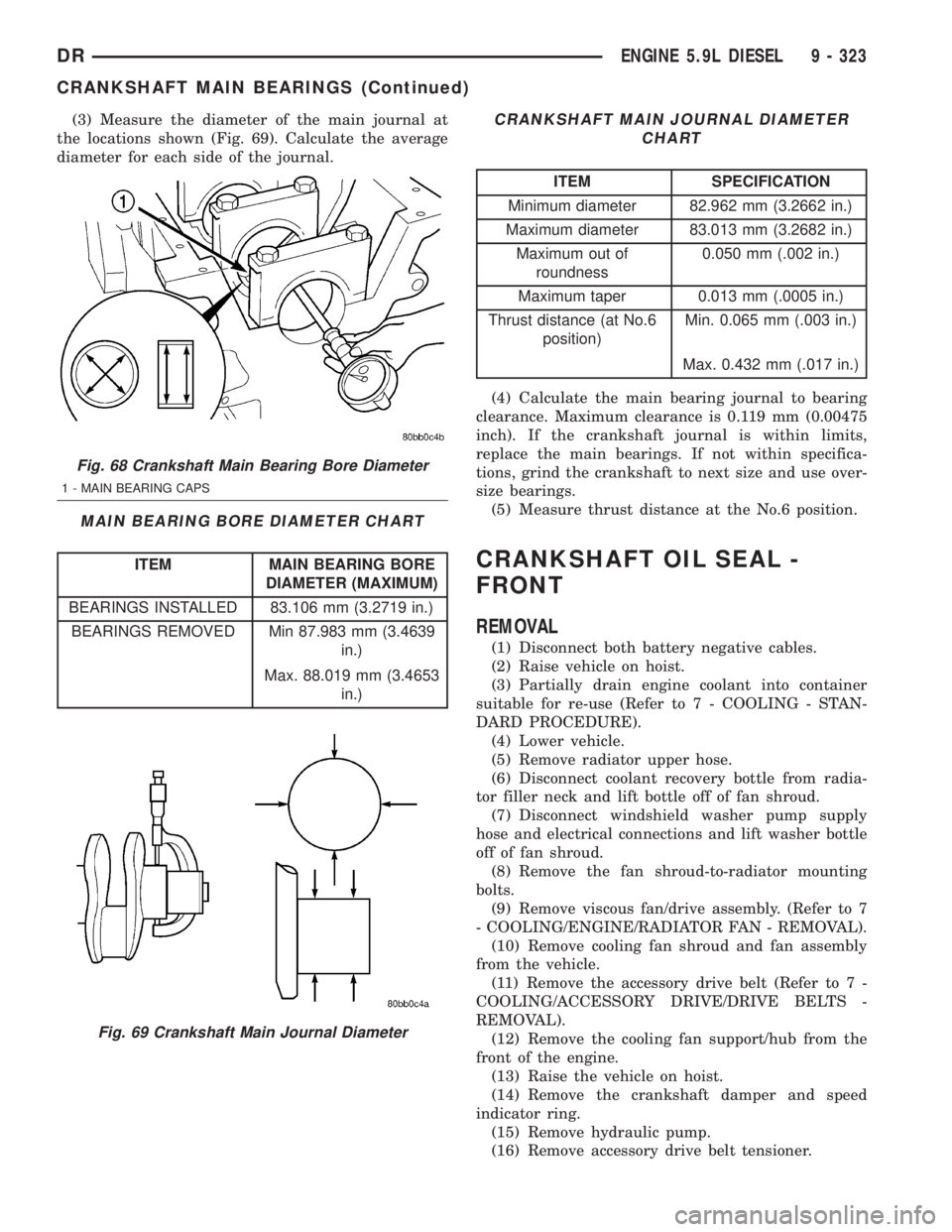
(3) Measure the diameter of the main journal at
the locations shown (Fig. 69). Calculate the average
diameter for each side of the journal.
MAIN BEARING BORE DIAMETER CHART
ITEM MAIN BEARING BORE
DIAMETER (MAXIMUM)
BEARINGS INSTALLED 83.106 mm (3.2719 in.)
BEARINGS REMOVED Min 87.983 mm (3.4639
in.)
Max. 88.019 mm (3.4653
in.)
CRANKSHAFT MAIN JOURNAL DIAMETER
CHART
ITEM SPECIFICATION
Minimum diameter 82.962 mm (3.2662 in.)
Maximum diameter 83.013 mm (3.2682 in.)
Maximum out of
roundness0.050 mm (.002 in.)
Maximum taper 0.013 mm (.0005 in.)
Thrust distance (at No.6
position)Min. 0.065 mm (.003 in.)
Max. 0.432 mm (.017 in.)
(4) Calculate the main bearing journal to bearing
clearance. Maximum clearance is 0.119 mm (0.00475
inch). If the crankshaft journal is within limits,
replace the main bearings. If not within specifica-
tions, grind the crankshaft to next size and use over-
size bearings.
(5) Measure thrust distance at the No.6 position.
CRANKSHAFT OIL SEAL -
FRONT
REMOVAL
(1) Disconnect both battery negative cables.
(2) Raise vehicle on hoist.
(3) Partially drain engine coolant into container
suitable for re-use (Refer to 7 - COOLING - STAN-
DARD PROCEDURE).
(4) Lower vehicle.
(5) Remove radiator upper hose.
(6) Disconnect coolant recovery bottle from radia-
tor filler neck and lift bottle off of fan shroud.
(7) Disconnect windshield washer pump supply
hose and electrical connections and lift washer bottle
off of fan shroud.
(8) Remove the fan shroud-to-radiator mounting
bolts.
(9) Remove viscous fan/drive assembly. (Refer to 7
- COOLING/ENGINE/RADIATOR FAN - REMOVAL).
(10) Remove cooling fan shroud and fan assembly
from the vehicle.
(11) Remove the accessory drive belt (Refer to 7 -
COOLING/ACCESSORY DRIVE/DRIVE BELTS -
REMOVAL).
(12) Remove the cooling fan support/hub from the
front of the engine.
(13) Raise the vehicle on hoist.
(14) Remove the crankshaft damper and speed
indicator ring.
(15) Remove hydraulic pump.
(16) Remove accessory drive belt tensioner.
Fig. 68 Crankshaft Main Bearing Bore Diameter
1 - MAIN BEARING CAPS
Fig. 69 Crankshaft Main Journal Diameter
DRENGINE 5.9L DIESEL 9 - 323
CRANKSHAFT MAIN BEARINGS (Continued)
Page 1576 of 2895
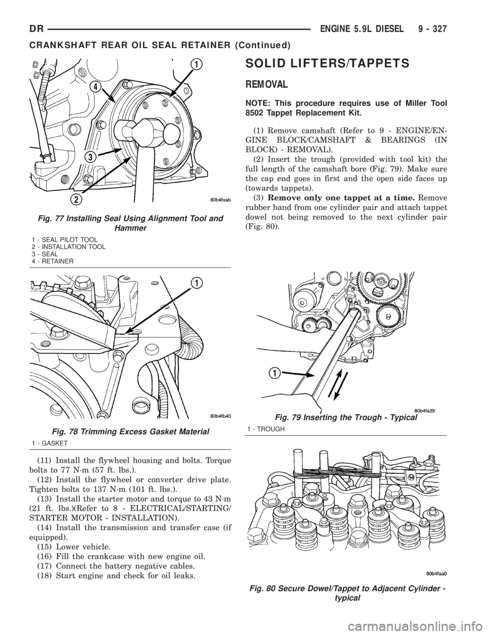
(11) Install the flywheel housing and bolts. Torque
bolts to 77 N´m (57 ft. lbs.).
(12) Install the flywheel or converter drive plate.
Tighten bolts to 137 N´m (101 ft. lbs.).
(13) Install the starter motor and torque to 43 N´m
(21 ft. lbs.)(Refer to 8 - ELECTRICAL/STARTING/
STARTER MOTOR - INSTALLATION).
(14) Install the transmission and transfer case (if
equipped).
(15) Lower vehicle.
(16) Fill the crankcase with new engine oil.
(17) Connect the battery negative cables.
(18) Start engine and check for oil leaks.
SOLID LIFTERS/TAPPETS
REMOVAL
NOTE: This procedure requires use of Miller Tool
8502 Tappet Replacement Kit.
(1) Remove camshaft (Refer to 9 - ENGINE/EN-
GINE BLOCK/CAMSHAFT & BEARINGS (IN
BLOCK) - REMOVAL).
(2) Insert the trough (provided with tool kit) the
full length of the camshaft bore (Fig. 79). Make sure
the cap end goes in first and the open side faces up
(towards tappets).
(3)Remove only one tappet at a time.Remove
rubber band from one cylinder pair and attach tappet
dowel not being removed to the next cylinder pair
(Fig. 80).
Fig. 79 Inserting the Trough - Typical
1 - TROUGH
Fig. 80 Secure Dowel/Tappet to Adjacent Cylinder -
typical
Fig. 77 Installing Seal Using Alignment Tool and
Hammer
1 - SEAL PILOT TOOL
2 - INSTALLATION TOOL
3 - SEAL
4 - RETAINER
Fig. 78 Trimming Excess Gasket Material
1 - GASKET
DRENGINE 5.9L DIESEL 9 - 327
CRANKSHAFT REAR OIL SEAL RETAINER (Continued)
Page 1597 of 2895
(8) Install the oil drain tube and a new gasket to
the turbocharger. Tighten the drain tube bolts to 24
N´m (18 ft. lbs.) torque.
(9)Pre-lube the turbocharger.Pour 50 to 60 cc
(2 to 3 oz.) clean engine oil in the oil supply line fit-
ting on the turbo. Rotate the turbocharger impeller
by hand to distrubute the oil thoroughly.
(10) Install and tighten the oil supply line fitting
nut to 24 N´m (18 ft. lbs.) torque.
(11) Position the charge air cooler inlet pipe to the
turbocharger. With the clamp in position, tighten the
clamp nut to 8 N´m (72 in. lbs.) torque.
(12) Position the air inlet hose to the turbocharger.
Tighten the clamp to 8 N´m (72 in. lbs.) torque.
(13) Raise vehicle on hoist.
(14) Connect the exhaust pipe to the turbocharger
and tighten the bolts to 34 N´m (25 ft. lbs.) torque.
(15) Lower the vehicle.
(16) Connect the battery negative cables.
(17) Start the engine to check for leaks.
VALVE TIMING
STANDARD PROCEDURE - TIMING
VERIFICATION
(1) Remove the cylinder head cover(Refer to 9 -
ENGINE/CYLINDER HEAD/CYLINDER HEAD
COVER(S) - REMOVAL).
(2) Remove fuel injector from cylinder number
1(Refer to 14 - FUEL SYSTEM/FUEL INJECTION/
FUEL INJECTOR - REMOVAL).
(3) Using Special Tool 7471B rotate the engine
until the TDC mark on the damper is at 12 o'clock.
(4) Using a 8 in.x 1/4 in. dowel rod inserted into
cylinder number 1, rock the crankshaft back and
forth to verify piston number 1 is at TDC.
(5) With cylinder number still at TDC, inspect the
keyway on the crankshaft gear for proper alignment
(12 o'clock position).
(6) If the keyway is not at 12 o'clock position
replace the crankshaft gear assembly.
(7) If the keyway is at 12 o'clock position, remove
front gear cover and verify timing mark alignment
between the camshaft gear and crankshaft gear, if
not aligned inspect keyway on camshaft gear.
(8) Inspect keyway on camshaft gear for proper
alignment with the key in the camshaft, if alignment
is off replace the camshaft/gear assembly.
(9) If timing marks alignment is off and no dam-
age is found at either the crankshaft or camshaft
gear keyways, realign timing marks as necessary.
GEAR HOUSING
REMOVAL
(1) Disconnect the battery negative cables.
(2) Raise vehicle on hoist.
(3) Partially drain engine coolant into container
suitable for re-use (Refer to 7 - COOLING - STAN-
DARD PROCEDURE).
(4) Lower vehicle.
(5) Remove radiator upper hose.
(6) Disconnect coolant recovery bottle hose from
radiator filler neck and lift bottle off of fan shroud.
(7) Disconnect windshield washer pump supply
hose and electrical connections and lift washer bottle
off of fan shroud.
(8) Remove lower fan shroud fasteners. Disconnect
fan drive wire harness.
(9) Remove the upper fan shroud-to-radiator
mounting bolts.
(10) Remove viscous fan/drive assembly (Refer to 7
- COOLING/ENGINE/RADIATOR FAN - REMOVAL).
(11) Remove the accessory drive belt (Refer to 7 -
COOLING/ACCESSORY DRIVE/DRIVE BELTS -
REMOVAL).
(12) Remove the cooling fan support/hub from the
front of the engine.
(13) Raise the vehicle on hoist.
(14) Remove the crankshaft damper (Refer to 9 -
ENGINE/ENGINE BLOCK/VIBRATION DAMPER -
REMOVAL) and speed indicator ring.
(15) Lower the vehicle.
(16) Remove the hydraulic pump.
(17) Remove the accessory drive belt tensioner.
(18) Remove the gear cover-to-housing bolts and
gently pry the cover away from the housing, taking
care not to mar the gasket surfaces.
(19) Remove the fuel injection pump (Refer to 14 -
FUEL SYSTEM/FUEL DELIVERY/FUEL INJEC-
TION PUMP - REMOVAL).
(20) Disconnect the camshaft position sensor con-
nector.
(21) Disconnect and remove engine speed sensor.
(22) Remove the camshaft (Refer to 9 - ENGINE/
ENGINE BLOCK/CAMSHAFT & BEARINGS (IN
BLOCK) - REMOVAL).
(23) Remove the six front oil pan fasteners.
(24) Remove the gear housing fasteners.
NOTE: Use care when removing the gear housing,
to avoid damage to the oil pan gasket, as the gas-
ket will be reused if it is not damaged.
(25) Slide a feeler gauge between the gear housing
and oil pan gasket, to break the gasket seal.
(26) Remove the gear housing and gasket.
9 - 348 ENGINE 5.9L DIESELDR
EXHAUST MANIFOLD (Continued)
Page 1598 of 2895
(27) Clean the gasket material from the cylinder
block and gear housing.
INSTALLATION
(1) Inspect oil pan gasket. If torn, gasket must be
replaced.
(2) Install a new gasket and the gear housing.
Torque bolts to 24 N´m (18 ft. lbs.). Follow torque
sequence.
(3) If a new housing is installed, the camshaft
position sensor, and engine speed sensor must be
transferred to the new housing.
(4) Connect the camshaft position sensor connec-
tor.
(5) Install and connect engine speed sensor.
(6) Install the injection pump (Refer to 14 - FUEL
SYSTEM/FUEL DELIVERY/FUEL INJECTION
PUMP - INSTALLATION).
(7) Install the camshaft (Refer to 9 - ENGINE/EN-
GINE BLOCK/CAMSHAFT & BEARINGS (IN
BLOCK) - INSTALLATION). Align the crankshaft
and camshaft gear marks as shown in.
(8) Install a new front crankshaft seal into the
gear cover.
(9) Apply a bead of MopartSilicone Rubber Adhe-
sive Sealant or equivalent to the gear housing cover.
Be sure to surround all through holes.
(10) Using the seal pilot to align the cover, install
the cover to the housing and install the bolts.
Tighten the bolts to 24 N´m (18 ft. lbs.) torque.
(11) Remove the seal pilot. Install front seal dust
shield.
(12) Raise the vehicle.
(13) Trim any excess gear housing gasket to make
it flush with the oil pan rail.
(14) Install the crankshaft damper and speed indi-
cator ring (Refer to 9 - ENGINE/ENGINE BLOCK/
VIBRATION DAMPER - INSTALLATION). Torque
bolts to 40 Nm (30 ft. lbs.), plus an additional 60É.
(15) Lower vehicle.
(16) Install the fan support/hub assembly and
tighten bolts to 32 N´m (24 ft. lbs.) torque.
(17) Install the hydraulic pump.
(18) Install the accessory drive belt tensioner.
Torque bolt to 43 N´m (32 ft. lbs.) torque.
(19) Install the accessory drive belt (Refer to 7 -
COOLING/ACCESSORY DRIVE/DRIVE BELTS -
INSTALLATION).
(20) Install the upper cooling fan and shroud
together (Refer to 7 - COOLING/ENGINE/RADIA-
TOR FAN - INSTALLATION).(21) Install lower shroud and connect fan drive
harness connector.
(22) Install the windshield washer reservoir to the
fan shroud and connect the washer pump supply
hose and electrical connection.
(23) Install the coolant recovery bottle to the fan
shroud and connect the hose to the radiator filler
neck.
(24) Install the radiator upper hose and clamps.
(25) Add engine oil.
(26) Add coolant (Refer to 7 - COOLING - STAN-
DARD PROCEDURE).
(27) Connect the battery cables.
(28) Start engine and inspect for leaks.
GEAR HOUSING COVER
REMOVAL
(1) Disconnect both battery negative cables.
(2) Raise vehicle on hoist.
(3) Partially drain engine coolant into container
suitable for re-use (Refer to 7 - COOLING - STAN-
DARD PROCEDURE).
(4) Lower vehicle.
(5) Remove radiator upper hose.
(6) Disconnect coolant recovery bottle hose from
radiator filler neck and lift bottle off of fan shroud.
(7) Disconnect windshield washer pump supply
hose and electrical connections and lift washer bottle
off of fan shroud.
(8) Remove viscous fan/drive assembly (Refer to 7 -
COOLING/ENGINE/RADIATOR FAN - REMOVAL).
(9) Remove the accessory drive belt (Refer to 7 -
COOLING/ACCESSORY DRIVE/DRIVE BELTS -
REMOVAL).
(10) Remove the cooling fan support/hub from the
front of the engine.
(11) Raise the vehicle on hoist.
(12) Remove power steering pump.
(13) Remove accessory drive belt tensioner.
(14) Remove the crankshaft damper and speed
indicator ring (Refer to 9 - ENGINE/ENGINE
BLOCK/VIBRATION DAMPER - REMOVAL).
(15) Lower the vehicle.
(16) Remove the gear cover-to-housing bolts and
gently pry the cover away from the housing, taking
care not to mar the gasket surfaces.
DRENGINE 5.9L DIESEL 9 - 349
GEAR HOUSING (Continued)
Page 1599 of 2895
INSTALLATION
(1) Install a new front crankshaft oil seal.
(2) Obtain a seal pilot/installation tool from a
crankshaft front seal service kit and install the pilot
into the seal.
(3) Apply a bead of MopartSilicone Rubber Adhe-
sive Sealant or equivalent to the gear housing cover.
Be sure to surround all through holes.
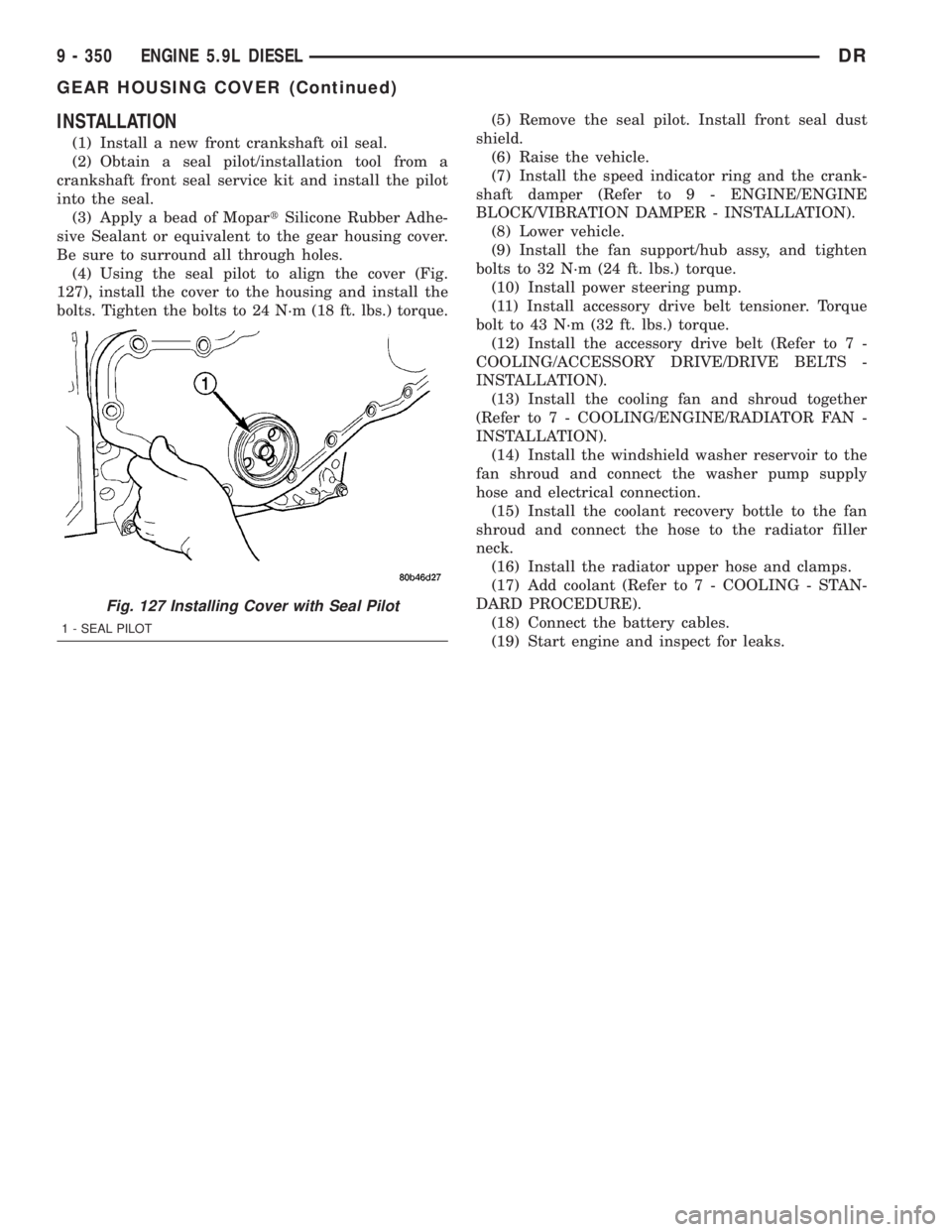
(4) Using the seal pilot to align the cover (Fig.
127), install the cover to the housing and install the
bolts. Tighten the bolts to 24 N´m (18 ft. lbs.) torque.(5) Remove the seal pilot. Install front seal dust
shield.
(6) Raise the vehicle.
(7) Install the speed indicator ring and the crank-
shaft damper (Refer to 9 - ENGINE/ENGINE
BLOCK/VIBRATION DAMPER - INSTALLATION).
(8) Lower vehicle.
(9) Install the fan support/hub assy, and tighten
bolts to 32 N´m (24 ft. lbs.) torque.
(10) Install power steering pump.
(11) Install accessory drive belt tensioner. Torque
bolt to 43 N´m (32 ft. lbs.) torque.
(12) Install the accessory drive belt (Refer to 7 -
COOLING/ACCESSORY DRIVE/DRIVE BELTS -
INSTALLATION).
(13) Install the cooling fan and shroud together
(Refer to 7 - COOLING/ENGINE/RADIATOR FAN -
INSTALLATION).
(14) Install the windshield washer reservoir to the
fan shroud and connect the washer pump supply
hose and electrical connection.
(15) Install the coolant recovery bottle to the fan
shroud and connect the hose to the radiator filler
neck.
(16) Install the radiator upper hose and clamps.
(17) Add coolant (Refer to 7 - COOLING - STAN-
DARD PROCEDURE).
(18) Connect the battery cables.
(19) Start engine and inspect for leaks.
Fig. 127 Installing Cover with Seal Pilot
1 - SEAL PILOT
9 - 350 ENGINE 5.9L DIESELDR
GEAR HOUSING COVER (Continued)