2003 DODGE RAM electrical
[x] Cancel search: electricalPage 1390 of 2895
PISTON RING SPECIFICATION CHART
Ring Position Groove Maximum
Clearance Clearance
Upper Ring .051-.094mm 0.11mm
(0.0020- .0037
in.)(0.004 in.)
Intermediate
Ring0.04-0.08mm 0.10mm
(0.0016-0.0031
in.)(0.004 in.)
Oil Control Ring .019-.229mm .25mm
(Steel Rails) (.0007-.0090
in.)(0.010 in.)
Ring Position Ring Gap Wear Limit
Upper Ring 0.20-0.36mm 0.43mm
(0.0079-0.0142
in.)(0.0017 in.)
Intermediate
Ring0.37-0.63mm 0.74mm
(0.0146-0.0249
in.)(0.029 in.)
Oil Control Ring 0.025-0.76mm 1.55mm
(Steel Rail) (0.0099- 0.03
in.)(0.061 in.)
(7) The No. 1 and No. 2 piston rings have a differ-
ent cross section. Ensure No. 2 ring is installed with
manufacturers I.D. mark (Dot) facing up, towards top
of the piston.
NOTE: Piston rings are installed in the following
order:
²Oil ring expander.
²Upper oil ring side rail.
²Lower oil ring side rail.
²No. 2 Intermediate piston ring.
²No. 1 Upper piston ring.
(8) Install the oil ring expander.
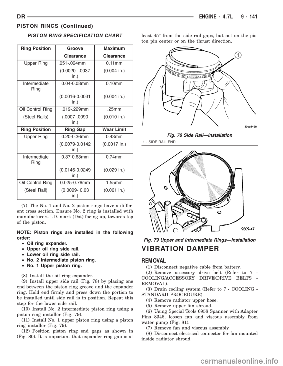
(9) Install upper side rail (Fig. 78) by placing one
end between the piston ring groove and the expander
ring. Hold end firmly and press down the portion to
be installed until side rail is in position. Repeat this
step for the lower side rail.
(10) Install No. 2 intermediate piston ring using a
piston ring installer (Fig. 79).
(11) Install No. 1 upper piston ring using a piston
ring installer (Fig. 79).
(12) Position piston ring end gaps as shown in
(Fig. 80). It is important that expander ring gap is atleast 45É from the side rail gaps, but not on the pis-
ton pin center or on the thrust direction.
VIBRATION DAMPER
REMOVAL
(1) Disconnect negative cable from battery.
(2) Remove accessory drive belt (Refer to 7 -
COOLING/ACCESSORY DRIVE/DRIVE BELTS -
REMOVAL).
(3) Drain cooling system (Refer to 7 - COOLING -
STANDARD PROCEDURE).
(4) Remove radiator upper hose.
(5) Remove upper fan shroud.
(6) Using Special Tools 6958 Spanner with Adapter
Pins 8346, loosen fan and viscous assembly from
water pump (Fig. 81).
(7) Remove fan and viscous assembly.
(8) Disconnect electrical connector for fan mounted
inside radiator shroud.
Fig. 78 Side RailÐInstallation
1 - SIDE RAIL END
Fig. 79 Upper and Intermediate RingsÐInstallation
DRENGINE - 4.7L 9 - 141
PISTON RINGS (Continued)
Page 1392 of 2895
(6) Install radiator upper shroud and tighten fas-
teners to 11 N´m (95 in. lbs.).
(7) Connect electrical connector for shroud fan.
(8) Install radiator upper hose.
(9) Install accessory drive belt (Refer to 7 - COOL-
ING/ACCESSORY DRIVE/DRIVE BELTS - INSTAL-
LATION).(10) Refill cooling system (Refer to 7 - COOLING -
STANDARD PROCEDURE).
(11) Connect negative cable to battery.
STRUCTURAL COVER
DESCRIPTION
The structural dust cover is made of die cast alu-
minum and joins the lower half of the transmission
bell housing to the engine bedplate.
OPERATION
The structural cover provides additional power-
train stiffness and reduces noise and vibration.
REMOVAL
(1) Raise vehicle on hoist.
(2) Remove the left hand exhaust pipe from
exhaust manifold.
(3) Loosen the right hand exhaust manifold-to-ex-
haust pipe retaining bolts.
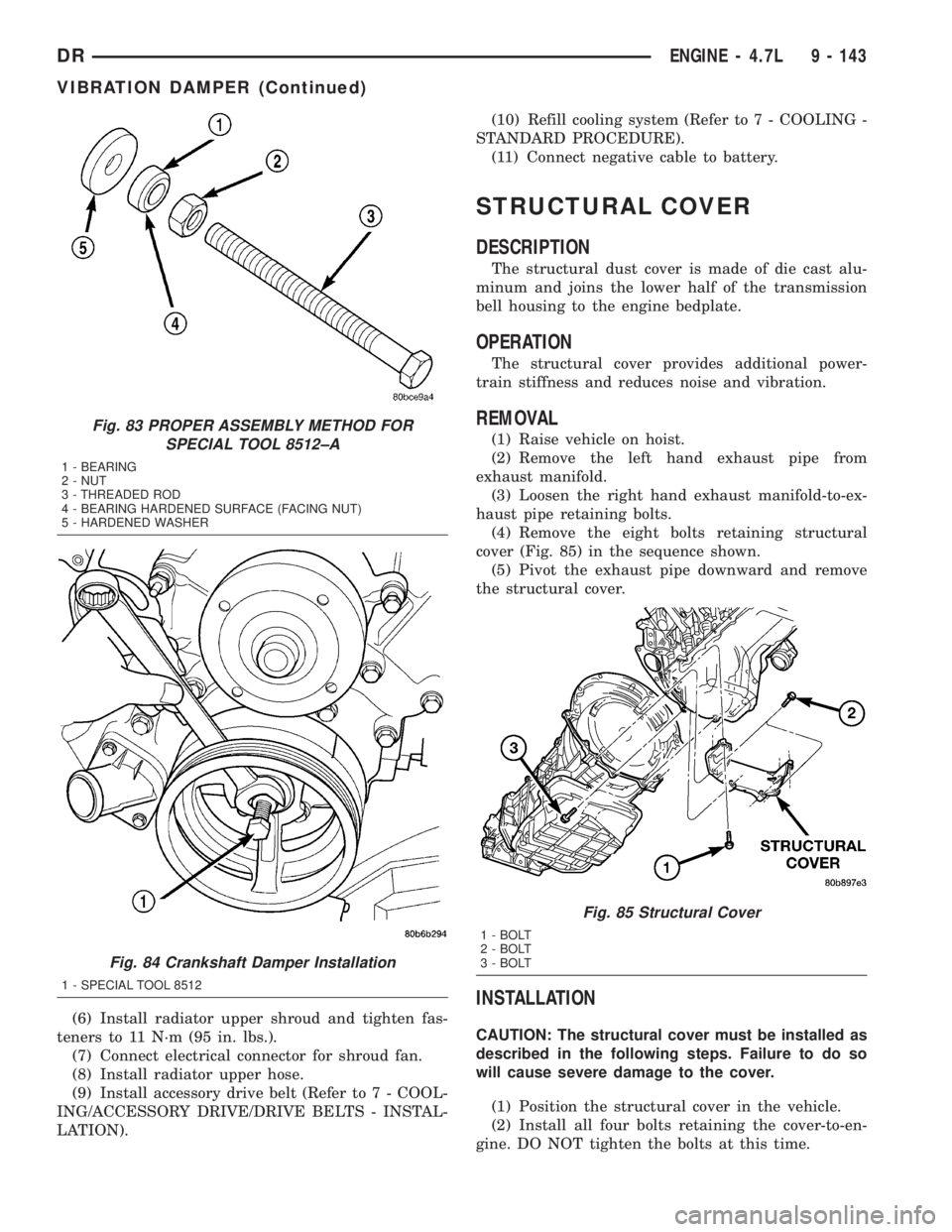
(4) Remove the eight bolts retaining structural
cover (Fig. 85) in the sequence shown.
(5) Pivot the exhaust pipe downward and remove
the structural cover.
INSTALLATION
CAUTION: The structural cover must be installed as
described in the following steps. Failure to do so
will cause severe damage to the cover.
(1) Position the structural cover in the vehicle.
(2) Install all four bolts retaining the cover-to-en-
gine. DO NOT tighten the bolts at this time.
Fig. 83 PROPER ASSEMBLY METHOD FOR
SPECIAL TOOL 8512±A
1 - BEARING
2 - NUT
3 - THREADED ROD
4 - BEARING HARDENED SURFACE (FACING NUT)
5 - HARDENED WASHER
Fig. 84 Crankshaft Damper Installation
1 - SPECIAL TOOL 8512
Fig. 85 Structural Cover
1 - BOLT
2 - BOLT
3 - BOLT
DRENGINE - 4.7L 9 - 143
VIBRATION DAMPER (Continued)
Page 1403 of 2895
OIL PRESSURE SENSOR/
SWITCH
DESCRIPTION
DESCRIPTION
The 3±wire, solid-state engine oil pressure sensor
(sending unit) is located in an engine oil pressure
gallery.
DESCRIPTION
The 3±wire, electrical/mechanical engine oil pres-
sure sensor (sending unit) is located in an engine oil
pressure gallery.
OPERATION
OPERATION
The oil pressure sensor uses three circuits. They
are:
²A 5±volt power supply from the Powertrain Con-
trol Module (PCM)
²A sensor ground through the PCM's sensor
return
²A signal to the PCM relating to engine oil pres-
sure
The oil pressure sensor has a 3±wire electrical
function very much like the Manifold Absolute Pres-
sure (MAP) sensor. Meaning different pressures
relate to different output voltages.
A 5±volt supply is sent to the sensor from the PCM
to power up the sensor. The sensor returns a voltage
signal back to the PCM relating to engine oil pres-
sure. This signal is then transferred (bussed) to the
instrument panel on either a CCD or PCI bus circuit
(depending on vehicle line) to operate the oil pressure
gauge and the check gauges lamp. Ground for the
sensor is provided by the PCM through a low-noise
sensor return.
OPERATION
The oil pressure sensor uses two circuits. They are:
²A signal to the PCM relating to engine oil pres-
sure
²A sensor ground through the PCM's sensor
return
The oil pressure sensor returns a voltage signal
back to the PCM relating to engine oil pressure. This
signal is then transferred (bussed) to the instrument
panel on a CCD bus circuit to operate the oil pres-
sure gauge and the check gauges lamp. Ground for
the sensor is provided by the PCM through a low-
noise sensor return.
REMOVAL
(1) Disconnect the negative cable from the battery.
(2) Raise vehicle on hoist.
(3) Remove front splash shield.
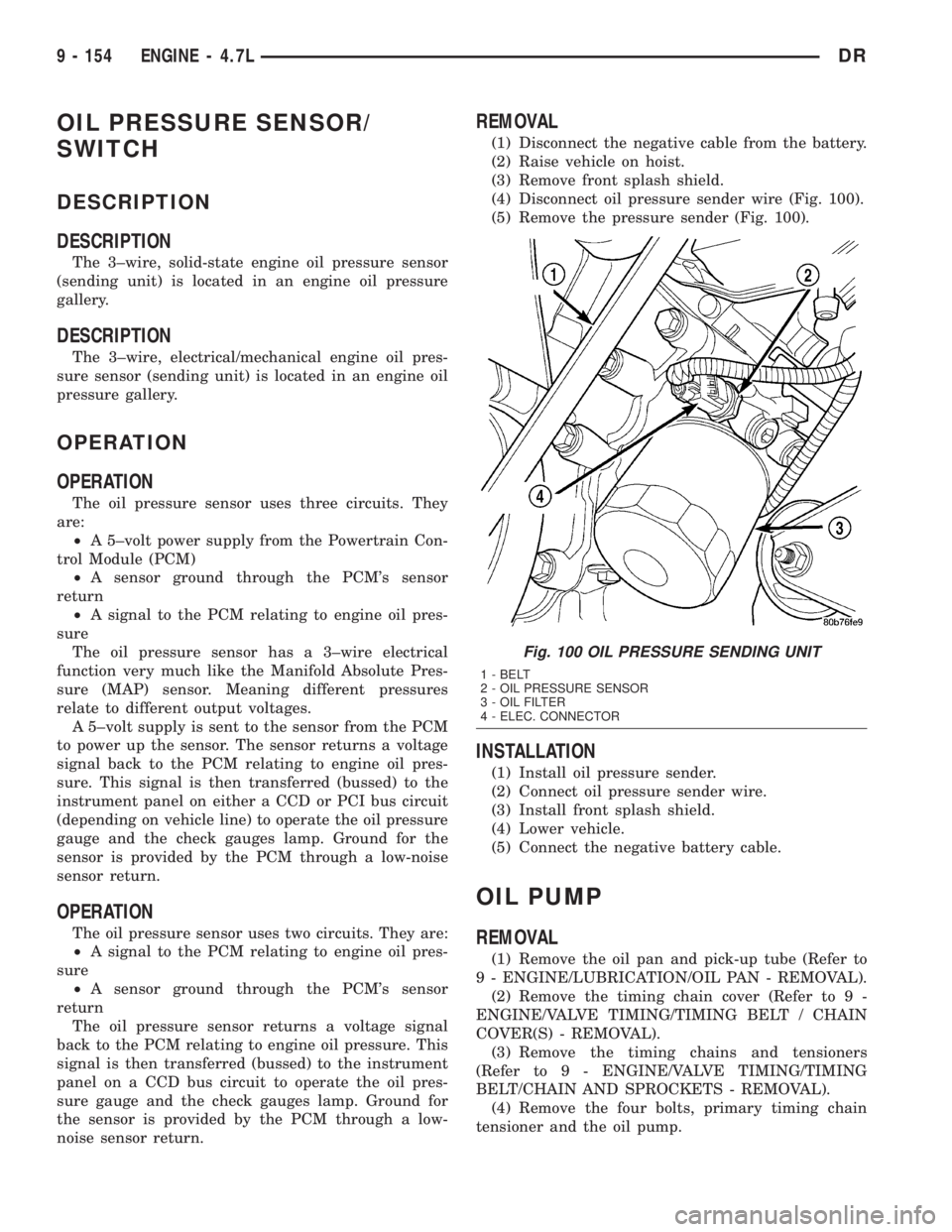
(4) Disconnect oil pressure sender wire (Fig. 100).
(5) Remove the pressure sender (Fig. 100).
INSTALLATION
(1) Install oil pressure sender.
(2) Connect oil pressure sender wire.
(3) Install front splash shield.
(4) Lower vehicle.
(5) Connect the negative battery cable.
OIL PUMP
REMOVAL
(1) Remove the oil pan and pick-up tube (Refer to
9 - ENGINE/LUBRICATION/OIL PAN - REMOVAL).
(2) Remove the timing chain cover (Refer to 9 -
ENGINE/VALVE TIMING/TIMING BELT / CHAIN
COVER(S) - REMOVAL).
(3) Remove the timing chains and tensioners
(Refer to 9 - ENGINE/VALVE TIMING/TIMING
BELT/CHAIN AND SPROCKETS - REMOVAL).
(4) Remove the four bolts, primary timing chain
tensioner and the oil pump.
Fig. 100 OIL PRESSURE SENDING UNIT
1 - BELT
2 - OIL PRESSURE SENSOR
3 - OIL FILTER
4 - ELEC. CONNECTOR
9 - 154 ENGINE - 4.7LDR
Page 1406 of 2895
INSTALLATION
(1) Position the oil pump onto the crankshaft and
install one oil pump retaining bolts.
(2) Position the primary timing chain tensioner
and install three retaining bolts.
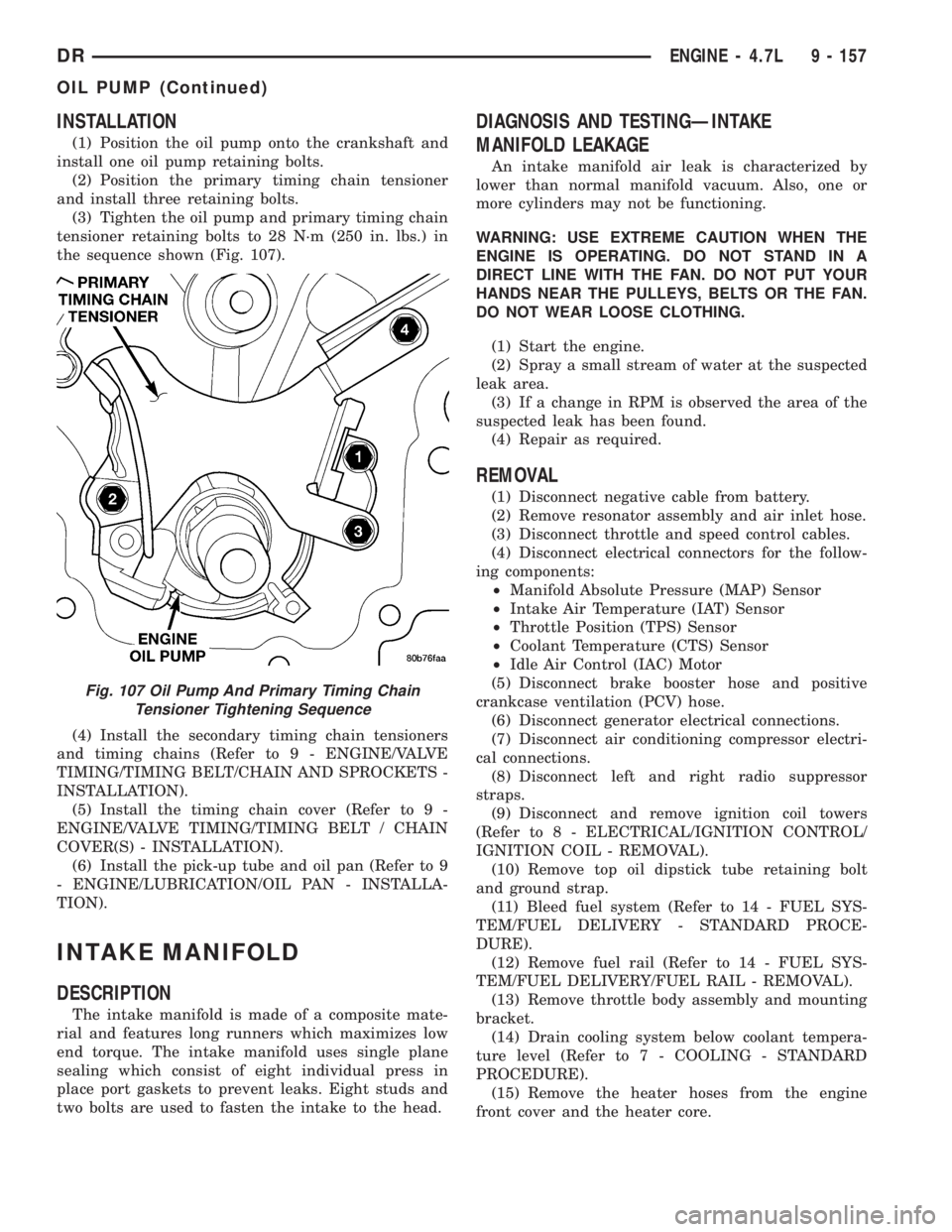
(3) Tighten the oil pump and primary timing chain
tensioner retaining bolts to 28 N´m (250 in. lbs.) in
the sequence shown (Fig. 107).
(4) Install the secondary timing chain tensioners
and timing chains (Refer to 9 - ENGINE/VALVE
TIMING/TIMING BELT/CHAIN AND SPROCKETS -
INSTALLATION).
(5) Install the timing chain cover (Refer to 9 -
ENGINE/VALVE TIMING/TIMING BELT / CHAIN
COVER(S) - INSTALLATION).
(6) Install the pick-up tube and oil pan (Refer to 9
- ENGINE/LUBRICATION/OIL PAN - INSTALLA-
TION).
INTAKE MANIFOLD
DESCRIPTION
The intake manifold is made of a composite mate-
rial and features long runners which maximizes low
end torque. The intake manifold uses single plane
sealing which consist of eight individual press in
place port gaskets to prevent leaks. Eight studs and
two bolts are used to fasten the intake to the head.
DIAGNOSIS AND TESTINGÐINTAKE
MANIFOLD LEAKAGE
An intake manifold air leak is characterized by
lower than normal manifold vacuum. Also, one or
more cylinders may not be functioning.
WARNING: USE EXTREME CAUTION WHEN THE
ENGINE IS OPERATING. DO NOT STAND IN A
DIRECT LINE WITH THE FAN. DO NOT PUT YOUR
HANDS NEAR THE PULLEYS, BELTS OR THE FAN.
DO NOT WEAR LOOSE CLOTHING.
(1) Start the engine.
(2) Spray a small stream of water at the suspected
leak area.
(3) If a change in RPM is observed the area of the
suspected leak has been found.
(4) Repair as required.
REMOVAL
(1) Disconnect negative cable from battery.
(2) Remove resonator assembly and air inlet hose.
(3) Disconnect throttle and speed control cables.
(4) Disconnect electrical connectors for the follow-
ing components:
²Manifold Absolute Pressure (MAP) Sensor
²Intake Air Temperature (IAT) Sensor
²Throttle Position (TPS) Sensor
²Coolant Temperature (CTS) Sensor
²Idle Air Control (IAC) Motor
(5) Disconnect brake booster hose and positive
crankcase ventilation (PCV) hose.
(6) Disconnect generator electrical connections.
(7) Disconnect air conditioning compressor electri-
cal connections.
(8) Disconnect left and right radio suppressor
straps.
(9) Disconnect and remove ignition coil towers
(Refer to 8 - ELECTRICAL/IGNITION CONTROL/
IGNITION COIL - REMOVAL).
(10) Remove top oil dipstick tube retaining bolt
and ground strap.
(11) Bleed fuel system (Refer to 14 - FUEL SYS-
TEM/FUEL DELIVERY - STANDARD PROCE-
DURE).
(12) Remove fuel rail (Refer to 14 - FUEL SYS-
TEM/FUEL DELIVERY/FUEL RAIL - REMOVAL).
(13) Remove throttle body assembly and mounting
bracket.
(14) Drain cooling system below coolant tempera-
ture level (Refer to 7 - COOLING - STANDARD
PROCEDURE).
(15) Remove the heater hoses from the engine
front cover and the heater core.
Fig. 107 Oil Pump And Primary Timing Chain
Tensioner Tightening Sequence
DRENGINE - 4.7L 9 - 157
OIL PUMP (Continued)
Page 1407 of 2895
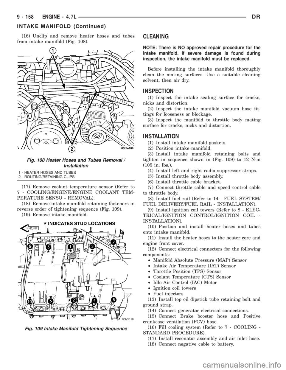
(16) Unclip and remove heater hoses and tubes
from intake manifold (Fig. 108).
(17) Remove coolant temperature sensor (Refer to
7 - COOLING/ENGINE/ENGINE COOLANT TEM-
PERATURE SENSO - REMOVAL).
(18) Remove intake manifold retaining fasteners in
reverse order of tightening sequence (Fig. 109).
(19) Remove intake manifold.CLEANING
NOTE: There is NO approved repair procedure for the
intake manifold. If severe damage is found during
inspection, the intake manifold must be replaced.
Before installing the intake manifold thoroughly
clean the mating surfaces. Use a suitable cleaning
solvent, then air dry.
INSPECTION
(1) Inspect the intake sealing surface for cracks,
nicks and distortion.
(2) Inspect the intake manifold vacuum hose fit-
tings for looseness or blockage.
(3) Inspect the manifold to throttle body mating
surface for cracks, nicks and distortion.
INSTALLATION
(1) Install intake manifold gaskets.
(2) Position intake manifold.
(3) Install intake manifold retaining bolts and
tighten in sequence shown in (Fig. 109) to 12 N´m
(105 in. lbs.).
(4) Install left and right radio suppressor straps.
(5) Install throttle body assembly.
(6) Install throttle cable bracket.
(7) Connect throttle cable and speed control cable
to throttle body.
(8) Install fuel rail (Refer to 14 - FUEL SYSTEM/
FUEL DELIVERY/FUEL RAIL - INSTALLATION).
(9) Install ignition coil towers (Refer to 8 - ELEC-
TRICAL/IGNITION CONTROL/IGNITION COIL -
INSTALLATION).
(10) Position and install heater hoses and tubes
onto intake manifold.
(11) Install the heater hoses to the heater core and
engine front cover.
(12) Connect electrical connectors for the following
components:
²Manifold Absolute Pressure (MAP) Sensor
²Intake Air Temperature (IAT) Sensor
²Throttle Position (TPS) Sensor
²Coolant Temperature (CTS) Sensor
²Idle Air Control (IAC) Motor
²Ignition coil towers
²Fuel injectors
(13) Install top oil dipstick tube retaining bolt and
ground strap.
(14) Connect generator electrical connections.
(15) Connect Brake booster hose and Positive
crankcase ventilation (PCV) hose.
(16) Fill cooling system (Refer to 7 - COOLING -
STANDARD PROCEDURE).
(17) Install resonator assembly and air inlet hose.
(18) Connect negative cable to battery.
Fig. 108 Heater Hoses and Tubes Removal /
Installation
1 - HEATER HOSES AND TUBES
2 - ROUTING/RETAINING CLIPS
Fig. 109 Intake Manifold Tightening Sequence
9 - 158 ENGINE - 4.7LDR
INTAKE MANIFOLD (Continued)
Page 1428 of 2895
(Refer to 9 - ENGINE - DIAGNOSIS AND TEST-
ING)ÐPERFORMANCE and (Refer to 9 - ENGINE -
DIAGNOSIS AND TESTING)ÐMECHANICAL for
possible causes and corrections of malfunctions.
(Refer to 14 - FUEL SYSTEM/FUEL DELIVERY -
DIAGNOSIS AND TESTING) and (Refer to 14 -
FUEL SYSTEM/FUEL INJECTION - DIAGNOSIS
AND TESTING) for the fuel system diagnosis.
Additional tests and diagnostic procedures may be
necessary for specific engine malfunctions that can
not be isolated with the Service Diagnosis charts.
Information concerning additional tests and diagno-
sis is provided within the following diagnosis:²Cylinder Compression Pressure Test (Refer to 9 -
ENGINE - DIAGNOSIS AND TESTING).
²Cylinder Combustion Pressure Leakage Test
(Refer to 9 - ENGINE - DIAGNOSIS AND TEST-
ING).
²Engine Cylinder Head Gasket Failure Diagnosis
(Refer to 9 - ENGINE/CYLINDER HEAD - DIAGNO-
SIS AND TESTING).
²Intake Manifold Leakage Diagnosis (Refer to 9 -
ENGINE/MANIFOLDS/INTAKE MANIFOLD -
DIAGNOSIS AND TESTING).
DIAGNOSIS AND TESTING - ENGINE DIAGNOSIS - PERFORMANCE
CONDITION POSSIBLE CAUSE CORRECTION
ENGINE WILL NOT START 1. Weak battery 1. Charge or replace as necessary.
2. Corroded or loose battery
connections.2. Clean and tighten battery
connections. Apply a coat of light
mineral grease to the terminals.
3. Faulty starter. 3. (Refer to 8 - ELECTRICAL/
STARTING - DIAGNOSIS AND
TESTING).
4. Faulty coil or control unit. 4. (Refer to 8 - ELECTRICAL/
IGNITION CONTROL/IGNITION
COIL - REMOVAL).
5. Incorrect spark plug gap. 5. (Refer to 8 - ELECTRICAL/
IGNITION CONTROL/SPARK PLUG
- CLEANING).
6. Dirt or water in fuel system. 6. Clean system and replace fuel
filter.
7. Faulty fuel pump, relay or wiring. 7. Repair or replace as necessary.
ENGINE STALLS OR ROUGH IDLE 1. Idle speed set to low. 1. (Refer to 14 - FUEL SYSTEM/
FUEL INJECTION/IDLE AIR
CONTROL MOTOR - REMOVAL).
2. Idle mixture too lean or too rich. 2. Refer to Powertrain Diagnosis
Information.
3. Vacuum leak. 3. Inspect intake manifold and
vacuum hoses, repair or replace as
necessary.
4. Faulty coil. 4. (Refer to 8 - ELECTRICAL/
IGNITION CONTROL/IGNITION
COIL - REMOVAL).
5. Incorrect engine timing. 5. (Refer to 9 - ENGINE/VALVE
TIMING - STANDARD
PROCEDURE).
DRENGINE - 5.7L 9 - 179
ENGINE - 5.7L (Continued)
Page 1429 of 2895
CONDITION POSSIBLE CAUSE CORRECTION
1. ENGINE LOSS OF POWER 1. Dirty or incorrectly gapped spark
plugs.1. (Refer to 8 - ELECTRICAL/
IGNITION CONTROL/SPARK PLUG
- CLEANING).
2. Dirt or water in fuel system. 2. Clean system and replace fuel
filter.
3. Faulty fuel pump. 3. (Refer to 14 - FUEL SYSTEM/
FUEL DELIVERY/FUEL PUMP -
DIAGNOSIS AND TESTING).
4. Blown cylinder head gasket. 4. Replace cylinder head gasket.
5. Low compression. 5. (Refer to 9 - ENGINE -
DIAGNOSIS AND TESTING).
6. Burned, warped or pitted valves. 6. Replace as necessary.
7. Plugged or restricted exhaust
system.7. Inspect and replace as
necessary.
8. Faulty coil. 8. (Refer to 8 - ELECTRICAL/
IGNITION CONTROL/IGNITION
COIL - REMOVAL).
1. ENGINE MISSES ON
ACCELERATION1. Spark plugs dirty or incorrectly
gapped.1. (Refer to 8 - ELECTRICAL/
IGNITION CONTROL/SPARK PLUG
- CLEANING).
2. Dirt in fuel system. 2. Clean fuel system.
3. Burned, warped or pitted valves. 3. Replcae as necessary.
4. Faulty coil. 4. (Refer to 8 - ELECTRICAL/
IGNITION CONTROL/IGNITION
COIL - REMOVAL).
1. ENGINE MISSES AT HIGH
SPEED1. Spark plugs dirty or incorrectly
gapped.1. (Refer to 8 - ELECTRICAL/
IGNITION CONTROL/SPARK PLUG
- CLEANING).
2. Faulty coil. 2. (Refer to 8 - ELECTRICAL/
IGNITION CONTROL/IGNITION
COIL - REMOVAL).
3. Dirt or water in fuel system. 3. Clean system and replace fuel
filter.
9 - 180 ENGINE - 5.7LDR
ENGINE - 5.7L (Continued)
Page 1435 of 2895
STANDARD PROCEDURE
STANDARD PROCEDURE - REPAIR DAMAGED
OR WORN THREADS
CAUTION: Be sure that the tapped holes maintain
the original center line.
Damaged or worn threads can be repaired. Essen-
tially, this repair consists of:
²Drilling out worn or damaged threads.
²Tapping the hole with a special Heli-Coil Tap, or
equivalent.
²Installing an insert into the tapped hole to bring
the hole back to its original thread size.
STANDARD PROCEDUREÐHYDROSTATIC
LOCK
CAUTION: DO NOT use the starter motor to rotate
the crankshaft. Severe damage could occur.
When an engine is suspected of hydrostatic lock
(regardless of what caused the problem), follow the
steps below.
(1) Perform the Fuel Pressure Release Procedure
(Refer to 14 - FUEL SYSTEM/FUEL DELIVERY -
STANDARD PROCEDURE).
(2) Disconnect the negative cable(s) from the bat-
tery.
(3) Inspect air cleaner, induction system, and
intake manifold to ensure system is dry and clear of
foreign material.
(4) Place a shop towel around the spark plugs to
catch any fluid that may possibly be under pressure
in the cylinder head. Remove the spark plugs.
(5) With all spark plugs removed, rotate the crank-
shaft using a breaker bar and socket.
(6) Identify the fluid in the cylinders (coolant, fuel,
oil, etc.).
(7) Be sure all fluid has been removed from the
cylinders.
(8) Repair engine or components as necessary to
prevent this problem from occurring again.
(9) Squirt a small amount of engine oil into the
cylinders to lubricate the walls. This will prevent
damage on restart.
(10) Install new spark plugs. Tighten the spark
plugs to 41 N´m (30 ft. lbs.) torque.
(11) Drain engine oil. Remove and discard the oil
filter.
(12) Install the drain plug. Tighten the plug to 34
N´m (25 ft. lbs.) torque.
(13) Install a new oil filter.(14) Fill engine crankcase with the specified
amount and grade of oil. (Refer to LUBRICATION &
MAINTENANCE - SPECIFICATIONS).
(15) Connect the negative cable(s) to the battery.
(16) Start the engine and check for any leaks.
REMOVAL
(1) Disconnect the battery negative cable.
(2) Remove the air cleaner resonator and duct
work as an assembly.
(3) Drain cooling system (Refer to 7 - COOLING -
STANDARD PROCEDURE).
(4) Remove the accessory drive belt (Refer to 7 -
COOLING/ACCESSORY DRIVE/DRIVE BELTS -
REMOVAL).
(5) Remove the viscous fan/drive (Refer to 7 -
COOLING/ENGINE/RADIATOR FAN - REMOVAL).
(6) Remove radiator (Refer to 7 - COOLING/EN-
GINE/RADIATOR - REMOVAL).
(7) Remove the upper crossmember and top core
support.
NOTE: It is not necessary to drain A/C system for
engine removal.
(8) Remove the A/C compressor with the lines
attached. Secure compressor out of the way.
(9) Remove generator assembly (Refer to 8 -
ELECTRICAL/CHARGING/GENERATOR - REMOV-
AL).
(10) Perform the Fuel System Pressure Release
procedure (Refer to 14 - FUEL SYSTEM/FUEL
DELIVERY - STANDARD PROCEDURE).
(11) Remove the intake manifold and IAFM as an
assembly(Refer to 9 - ENGINE/MANIFOLDS/IN-
TAKE MANIFOLD - REMOVAL).
(12) Disconnect the heater hoses.
NOTE: It is not necessary to disconnect P/S hoses
from pump, for P/S pump removal.
(13) Remove the power steering pump and set
aside.
(14) Disconnect the fuel supply line (Refer to 14 -
FUEL SYSTEM/FUEL DELIVERY/QUICK CON-
NECT FITTING - STANDARD PROCEDURE).
(15) Raise and support the vehicle on a hoist and
drain the engine oil.
(16) Remove engine front mount thru-bolt nuts.
(17) Disconnect the transmission oil cooler lines
from their retainers at the oil pan bolts.
(18) Disconnect exhaust pipe at manifolds.
(19) Disconnect the starter wires. Remove starter
motor (Refer to 8 - ELECTRICAL/STARTING/
STARTER MOTOR - REMOVAL).
9 - 186 ENGINE - 5.7LDR
ENGINE - 5.7L (Continued)