2003 DODGE RAM electrical
[x] Cancel search: electricalPage 1276 of 2895
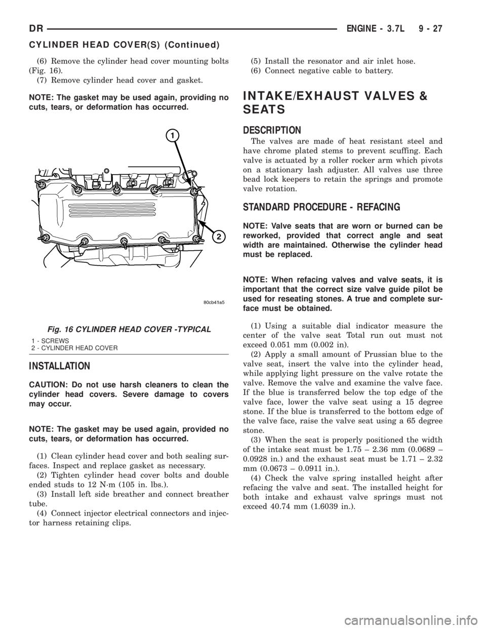
(6) Remove the cylinder head cover mounting bolts
(Fig. 16).
(7) Remove cylinder head cover and gasket.
NOTE: The gasket may be used again, providing no
cuts, tears, or deformation has occurred.
INSTALLATION
CAUTION: Do not use harsh cleaners to clean the
cylinder head covers. Severe damage to covers
may occur.
NOTE: The gasket may be used again, provided no
cuts, tears, or deformation has occurred.
(1) Clean cylinder head cover and both sealing sur-
faces. Inspect and replace gasket as necessary.
(2) Tighten cylinder head cover bolts and double
ended studs to 12 N´m (105 in. lbs.).
(3) Install left side breather and connect breather
tube.
(4) Connect injector electrical connectors and injec-
tor harness retaining clips.(5) Install the resonator and air inlet hose.
(6) Connect negative cable to battery.
INTAKE/EXHAUST VALVES &
SEATS
DESCRIPTION
The valves are made of heat resistant steel and
have chrome plated stems to prevent scuffing. Each
valve is actuated by a roller rocker arm which pivots
on a stationary lash adjuster. All valves use three
bead lock keepers to retain the springs and promote
valve rotation.
STANDARD PROCEDURE - REFACING
NOTE: Valve seats that are worn or burned can be
reworked, provided that correct angle and seat
width are maintained. Otherwise the cylinder head
must be replaced.
NOTE: When refacing valves and valve seats, it is
important that the correct size valve guide pilot be
used for reseating stones. A true and complete sur-
face must be obtained.
(1) Using a suitable dial indicator measure the
center of the valve seat Total run out must not
exceed 0.051 mm (0.002 in).
(2) Apply a small amount of Prussian blue to the
valve seat, insert the valve into the cylinder head,
while applying light pressure on the valve rotate the
valve. Remove the valve and examine the valve face.
If the blue is transferred below the top edge of the
valve face, lower the valve seat using a 15 degree
stone. If the blue is transferred to the bottom edge of
the valve face, raise the valve seat using a 65 degree
stone.
(3) When the seat is properly positioned the width
of the intake seat must be 1.75 ± 2.36 mm (0.0689 ±
0.0928 in.) and the exhaust seat must be 1.71 ± 2.32
mm (0.0673 ± 0.0911 in.).
(4) Check the valve spring installed height after
refacing the valve and seat. The installed height for
both intake and exhaust valve springs must not
exceed 40.74 mm (1.6039 in.).
Fig. 16 CYLINDER HEAD COVER -TYPICAL
1 - SCREWS
2 - CYLINDER HEAD COVER
DRENGINE - 3.7L 9 - 27
CYLINDER HEAD COVER(S) (Continued)
Page 1285 of 2895
(12) Remove cylinder head cover retaining bolts.
(13) Remove cylinder head cover.
INSTALLATION
CAUTION: Do not use harsh cleaners to clean the
cylinder head covers. Severe damage to covers
may occur.
NOTE: The gasket may be used again, provided no
cuts, tears, or deformation has occurred.
(1) Clean cylinder head cover and both sealing sur-
faces. Inspect and replace gasket as necessary.
(2) Tighten cylinder head cover bolts and double
ended studs to 12 N´m (105 in. lbs).
(3) Install right rear breather tube and filter
assembly.
(4) Connect injector, ignition coil electrical connec-
tors and harness retaining clips.
(5) Install the oil fill tube.
(6) Install PCV hose.
(7) Install heater hoses.
(8) Install air conditioning compressor retaining
bolts.
(9) Install accessory drive belt(Refer to 7 - COOL-
ING/ACCESSORY DRIVE/DRIVE BELTS - INSTAL-
LATION).
(10) Fill Cooling system(Refer to 7 - COOLING -
STANDARD PROCEDURE).
(11) Install air cleaner assembly, resonator assem-
bly and air inlet hose.
(12) Connect battery negative cable.
ROCKER ARM
DESCRIPTION
The rocker arms are steel stampings with an inte-
gral roller bearing. The rocker arms incorporate a 2.8
mm (0.11 inch) oil hole in the lash adjuster socket for
roller and camshaft lubrication.
REMOVAL
NOTE: Disconnect the battery negative cable to pre-
vent accidental starter engagement.
(1) Remove the cylinder head cover (Refer to 9 -
ENGINE/CYLINDER HEAD/CYLINDER HEAD
COVER(S) - REMOVAL).
(2) For rocker arm removal on cylinder #4, Rotate
the crankshaft until cylinder #1 is at BDC intake
stroke.(3) For rocker arm removal on cylinder #1, Rotate
the crankshaft until cylinder #1 is at BDC combus-
tion stroke.
(4) For rocker arm removal on cylinders #3 and #5,
Rotate the crankshaft until cylinder #1 is at TDC
exhaust stroke.
(5) For rocker arm removal on cylinders #2 and #6,
Rotate the crankshaft until cylinder #1 is at TDC
ignition stroke.
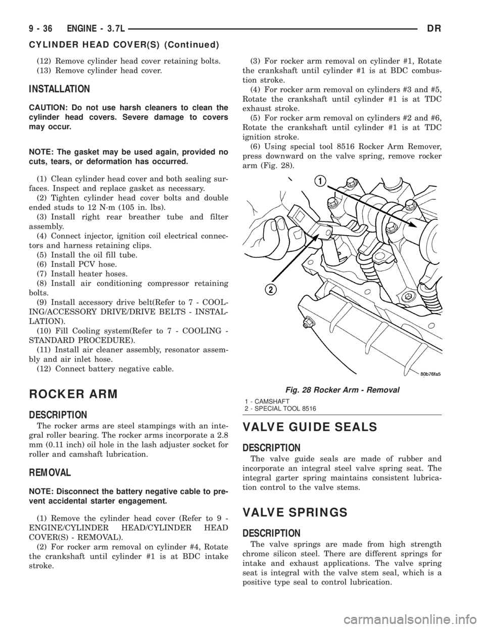
(6) Using special tool 8516 Rocker Arm Remover,
press downward on the valve spring, remove rocker
arm (Fig. 28).
VALVE GUIDE SEALS
DESCRIPTION
The valve guide seals are made of rubber and
incorporate an integral steel valve spring seat. The
integral garter spring maintains consistent lubrica-
tion control to the valve stems.
VALVE SPRINGS
DESCRIPTION
The valve springs are made from high strength
chrome silicon steel. There are different springs for
intake and exhaust applications. The valve spring
seat is integral with the valve stem seal, which is a
positive type seal to control lubrication.
Fig. 28 Rocker Arm - Removal
1 - CAMSHAFT
2 - SPECIAL TOOL 8516
9 - 36 ENGINE - 3.7LDR
CYLINDER HEAD COVER(S) (Continued)
Page 1293 of 2895
Crankshaft JOURNAL SIZE
SIZE mm (in.)
MARKING
(.0958 - .0960
in.)
Lower Bearing Main919and949
9192.441 - 2.447
mmUse with crankshaft
9R, S9
(.0961 -.0963
in.)
9292.435 - 2.441
mmUse with crankshaft
9T, U9
(.0958 - .0962
in.)
Lower Main Bearing929and939
9392.429 - 2.435
mmUse with crankshaft
9R, S9
(.0956 - .0958
in.)
9492.423 - 2.429
mmUse with crankshaft
9T, U9
(.0953 - .0956
in.)
Bearing Clearances
Main91, 49
Crankshaft
9R9.004 - .034 mm ( .00015 - .0013 in.)
Crankshaft
9S9.004 - .030 mm ( .00015 - .0011 in.)
Crankshaft
9T9.006 - .032 mm (.0002 - .0012 in.)
Crankshaft
9U9.002 - .032 mm (.00007 -. 0012 in.)
Main92, 39
Crankshaft
9R9.016 - .046 mm (.0006 - .0018 in.)
Crankshaft
9S9.016 - .042 mm (.00062 - .016 in.)
Crankshaft
9T9.018 - .044 mm (.0007 - .0017 in.)
Crankshaft
9U9.014 - .044 mm (.0005 - .0017 in.)CRANKSHAFT OIL SEAL -
FRONT
REMOVAL
(1) Disconnect negative cable from battery.
(2) Remove accessory drive belt (Refer to 7 -
COOLING/ACCESSORY DRIVE/DRIVE BELTS -
REMOVAL).
(3) Remove A/C compressor mouning fasteners and
set aside.
(4) Drain cooling system (Refer to 7 - COOLING -
STANDARD PROCEDURE).
(5) Remove upper radiator hose.
(6) Disconnect electrical connector for fan mounted
inside radiator shroud.
(7) Remove radiator shroud attaching fasteners.
NOTE: Transmission cooler line snaps into shroud
lower right hand corner.
(8) Remove radiator cooling fan and shroud (Refer
to 7 - COOLING/ENGINE/RADIATOR FAN -
REMOVAL).
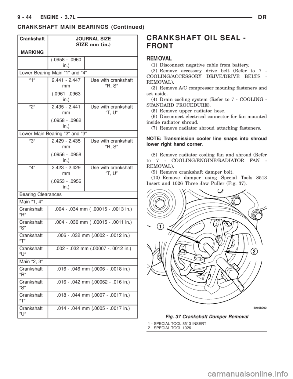
(9) Remove crankshaft damper bolt.
(10) Remove damper using Special Tools 8513
Insert and 1026 Three Jaw Puller (Fig. 37).
Fig. 37 Crankshaft Damper Removal
1 - SPECIAL TOOL 8513 INSERT
2 - SPECIAL TOOL 1026
9 - 44 ENGINE - 3.7LDR
CRANKSHAFT MAIN BEARINGS (Continued)
Page 1304 of 2895
(8) Disconnect electrical connector for fan mounted
inside radiator shroud.
NOTE: Transmission cooler line snaps into shroud
lower right hand corner.
(9) Remove crankshaft damper bolt.
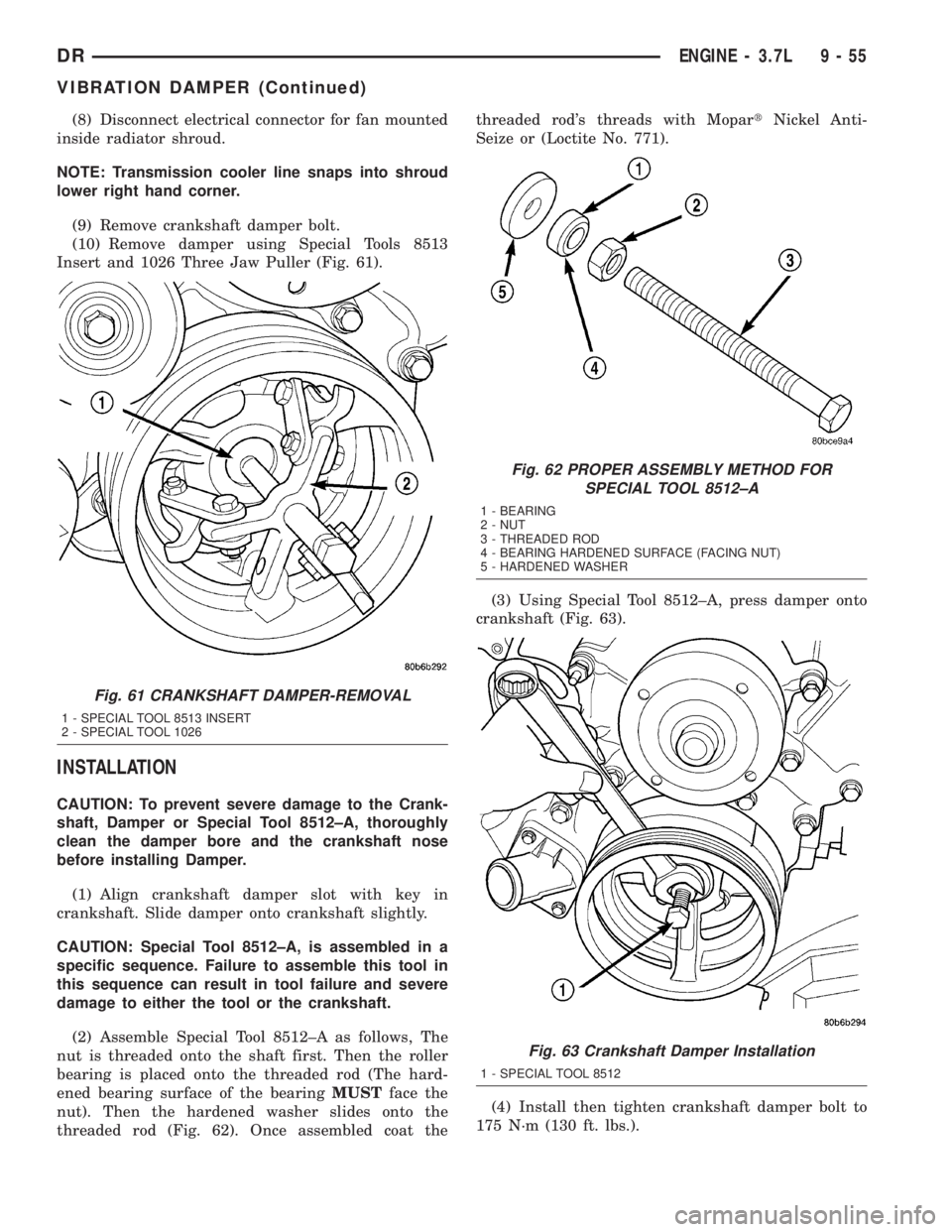
(10) Remove damper using Special Tools 8513
Insert and 1026 Three Jaw Puller (Fig. 61).
INSTALLATION
CAUTION: To prevent severe damage to the Crank-
shaft, Damper or Special Tool 8512±A, thoroughly
clean the damper bore and the crankshaft nose
before installing Damper.
(1) Align crankshaft damper slot with key in
crankshaft. Slide damper onto crankshaft slightly.
CAUTION: Special Tool 8512±A, is assembled in a
specific sequence. Failure to assemble this tool in
this sequence can result in tool failure and severe
damage to either the tool or the crankshaft.
(2) Assemble Special Tool 8512±A as follows, The
nut is threaded onto the shaft first. Then the roller
bearing is placed onto the threaded rod (The hard-
ened bearing surface of the bearingMUSTface the
nut). Then the hardened washer slides onto the
threaded rod (Fig. 62). Once assembled coat thethreaded rod's threads with MopartNickel Anti-
Seize or (Loctite No. 771).
(3) Using Special Tool 8512±A, press damper onto
crankshaft (Fig. 63).
(4) Install then tighten crankshaft damper bolt to
175 N´m (130 ft. lbs.).
Fig. 61 CRANKSHAFT DAMPER-REMOVAL
1 - SPECIAL TOOL 8513 INSERT
2 - SPECIAL TOOL 1026
Fig. 62 PROPER ASSEMBLY METHOD FOR
SPECIAL TOOL 8512±A
1 - BEARING
2 - NUT
3 - THREADED ROD
4 - BEARING HARDENED SURFACE (FACING NUT)
5 - HARDENED WASHER
Fig. 63 Crankshaft Damper Installation
1 - SPECIAL TOOL 8512
DRENGINE - 3.7L 9 - 55
VIBRATION DAMPER (Continued)
Page 1305 of 2895
(5) Install fan blade assembly (Refer to 7 - COOL-
ING/ENGINE/FAN DRIVE VISCOUS CLUTCH -
INSTALLATION).
(6) Install radiator upper shroud and tighten fas-
teners to 11 N´m (95 in. lbs.).
(7) Connect electrical connector for shroud fan.
(8) Install radiator upper hose.
(9) Install accessory drive belt (Refer to 7 - COOL-
ING/ACCESSORY DRIVE/DRIVE BELTS - INSTAL-
LATION).
(10) Refill cooling system (Refer to 7 - COOLING -
STANDARD PROCEDURE).
(11) Connect negative cable to battery.
STRUCTURAL COVER
DESCRIPTION
The structural dust cover is made of die cast alu-
minum and joins the lower half of the transmission
bell housing to the engine bedplate.
OPERATION
The structural cover provides additional power-
train stiffness and reduces noise and vibration.
REMOVAL
(1) Raise vehicle on hoist.
(2) Remove the left hand exhaust pipe from
exhaust manifold.
(3) Loosen the right hand exhaust manifold-to-ex-
haust pipe retaining bolts.
(4) Remove the eight bolts retaining structural
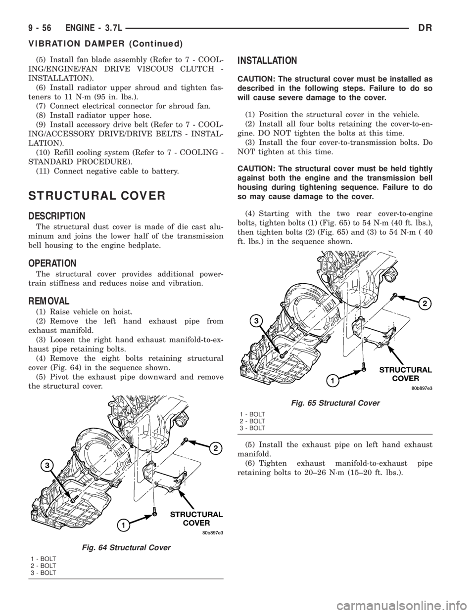
cover (Fig. 64) in the sequence shown.
(5) Pivot the exhaust pipe downward and remove
the structural cover.
INSTALLATION
CAUTION: The structural cover must be installed as
described in the following steps. Failure to do so
will cause severe damage to the cover.
(1) Position the structural cover in the vehicle.
(2) Install all four bolts retaining the cover-to-en-
gine. DO NOT tighten the bolts at this time.
(3) Install the four cover-to-transmission bolts. Do
NOT tighten at this time.
CAUTION: The structural cover must be held tightly
against both the engine and the transmission bell
housing during tightening sequence. Failure to do
so may cause damage to the cover.
(4) Starting with the two rear cover-to-engine
bolts, tighten bolts (1) (Fig. 65) to 54 N´m (40 ft. lbs.),
then tighten bolts (2) (Fig. 65) and (3) to 54 N´m ( 40
ft. lbs.) in the sequence shown.
(5) Install the exhaust pipe on left hand exhaust
manifold.
(6) Tighten exhaust manifold-to-exhaust pipe
retaining bolts to 20±26 N´m (15±20 ft. lbs.).
Fig. 64 Structural Cover
1 - BOLT
2 - BOLT
3 - BOLT
Fig. 65 Structural Cover
1 - BOLT
2 - BOLT
3 - BOLT
9 - 56 ENGINE - 3.7LDR
VIBRATION DAMPER (Continued)
Page 1315 of 2895

INSPECTION
(1) Inspect oil drain plug and plug hole for
stripped or damaged threads. Repair as necessary.
(2) Inspect the oil pan mounting flange for bends
or distortion. Straighten flange, if necessary.
INSTALLATION
(1) Clean the oil pan gasket mating surface of the
bedplate and oil pan.
(2) Inspect integrated oil pan gasket, and replace
as necessary.
(3) Position the integrated oil pan gasket/windage
tray assembly.
(4) Install the oil pickup tube
(5) Install the mounting bolt and nuts. Tighten
nuts to 28 N´m (20 ft. lbs.).
(6) Position the oil pan and install the mounting
bolts. Tighten the mounting bolts to 15 N´m (11 ft.
lbs.) in the sequence shown (Fig. 75).
(7) Lower the engine into mounts using special
tool # 8534.
(8) Install both the left and right side engine
mount through bolts. Tighten the nuts to 68 N´m (50
ft. lbs.).
(9) Remove special tool # 8534.
(10) Install structural dust cover, if equipped.
(11) Install the front crossmember(Refer to 13 -
FRAME & BUMPERS/FRAME/FRONT CROSS-
MEMBER - INSTALLATION).
(12) Fill engine oil.
(13) Reconnect the negative battery cable.
(14) Start engine and check for leaks.
OIL PRESSURE SENSOR/
SWITCH
DESCRIPTION
The 3±wire, solid-state engine oil pressure sensor
(sending unit) is located in an engine oil pressure
gallery.
OPERATION
The oil pressure sensor uses three circuits. They
are:²A 5±volt power supply from the Powertrain Con-
trol Module (PCM)
²A sensor ground through the PCM's sensor
return
²A signal to the PCM relating to engine oil pres-
sure
The oil pressure sensor has a 3±wire electrical
function very much like the Manifold Absolute Pres-
sure (MAP) sensor. Meaning different pressures
relate to different output voltages.
A 5±volt supply is sent to the sensor from the PCM
to power up the sensor. The sensor returns a voltage
signal back to the PCM relating to engine oil pres-
sure. This signal is then transferred (bussed) to the
instrument panel on either a CCD or PCI bus circuit
(depending on vehicle line) to operate the oil pressure
gauge and the check gauges lamp. Ground for the
sensor is provided by the PCM through a low-noise
sensor return.
Fig. 75 Oil Pan Mounting Bolt Sequence
9 - 66 ENGINE - 3.7LDR
OIL PAN (Continued)
Page 1321 of 2895
(2) Spray a small stream of water (spray bottle) at
the suspected leak area.
(3) If engine RPM'S change, the area of the sus-
pected leak has been found.
(4) Repair as required.
REMOVAL
(1) Disconnect negative cable from battery.
(2) Remove resonator assembly and air inlet hose.
(3) Disconnect throttle and speed control cables.
(4) Disconnect electrical connectors for the follow-
ing components: Refer to FUEL SYSTEM for compo-
nent locations.
²Manifold Absolute Pressure (MAP) Sensor
²Intake Air Temperature (IAT) Sensor
²Throttle Position (TPS) Sensor
²Coolant Temperature (CTS) Sensor
²Idle Air Control (IAC) Motor
(5) Disconnect vapor purge hose, brake booster
hose, speed control servo hose, positive crankcase
ventilation (PCV) hose.
(6) Disconnect generator electrical connections.
(7) Disconnect air conditioning compressor electri-
cal connections.(8) D
isconnect left and right radio suppressor straps.
(9) Disconnect and remove ignition coil towers.
(10) Remove top oil dipstick tube retaining bolt
and ground strap.
(11) Bleed fuel system. Refer to FUEL SYSTEM.
(12) Remove fuel rail.
(13) Remove throttle body assembly and mounting
bracket.
(14) Drain cooling system below coolant tempera-
ture level. Refer to COOLING SYSTEM.
(15) Remove the heater hoses from the engine
front cover and the heater core.
(16) Unclip and remove heater hoses and tubes
from intake manifold.
(17) Remove coolant temperature sensor. Refer to
FUEL SYSTEM.
(18) Remove intake manifold retaining fasteners in
reverse order of tightening sequence.
(19) Remove intake manifold.
INSTALLATION
(1) Install intake manifold gaskets.
(2) Install intake manifold.
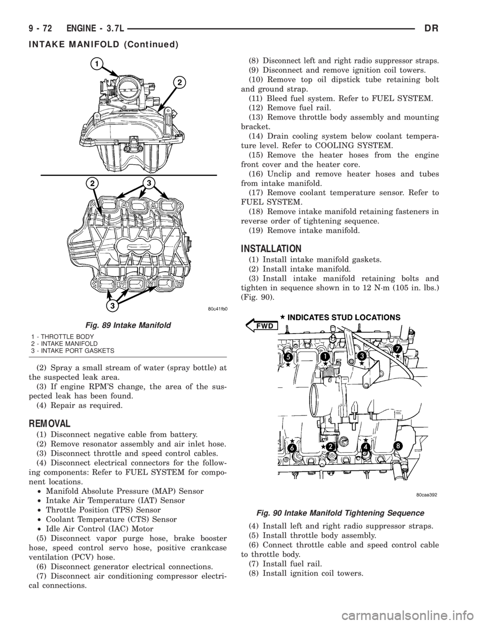
(3) Install intake manifold retaining bolts and
tighten in sequence shown in to 12 N´m (105 in. lbs.)
(Fig. 90).
(4) Install left and right radio suppressor straps.
(5) Install throttle body assembly.
(6) Connect throttle cable and speed control cable
to throttle body.
(7) Install fuel rail.
(8) Install ignition coil towers.
Fig. 89 Intake Manifold
1 - THROTTLE BODY
2 - INTAKE MANIFOLD
3 - INTAKE PORT GASKETS
Fig. 90 Intake Manifold Tightening Sequence
9 - 72 ENGINE - 3.7LDR
INTAKE MANIFOLD (Continued)
Page 1322 of 2895
(9) Position and install heater hoses and tubes
onto intake manifold.
(10) Install the heater hoses to the heater core and
engine front cover.
(11) Connect electrical connectors for the following
components:
²Manifold Absolute Pressure (MAP) Sensor
²Intake Air Temperature (IAT) Sensor
²Throttle Position (TPS) Sensor
²Coolant Temperature (CTS) Sensor
²Idle Air Control (IAC) Motor
²Ignition coil towers
²Fuel injectors
(12) Install top oil dipstick tube retaining bolt and
ground strap.
(13) Connect generator electrical connections.
(14) Connect Vapor purge hose, Brake booster
hose, Speed control servo hose, Positive crankcase
ventilation (PCV) hose.
(15) Fill cooling system.
(16) Install resonator assembly and air inlet hose.
(17) Connect negative cable to battery.
EXHAUST MANIFOLD
DESCRIPTION
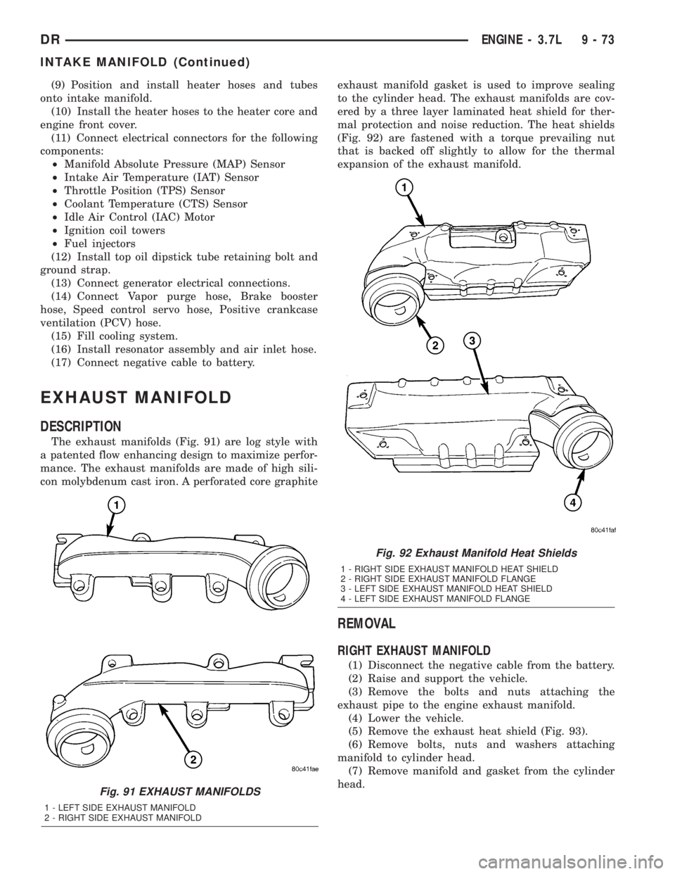
The exhaust manifolds (Fig. 91) are log style with
a patented flow enhancing design to maximize perfor-
mance. The exhaust manifolds are made of high sili-
con molybdenum cast iron. A perforated core graphiteexhaust manifold gasket is used to improve sealing
to the cylinder head. The exhaust manifolds are cov-
ered by a three layer laminated heat shield for ther-
mal protection and noise reduction. The heat shields
(Fig. 92) are fastened with a torque prevailing nut
that is backed off slightly to allow for the thermal
expansion of the exhaust manifold.
REMOVAL
RIGHT EXHAUST MANIFOLD
(1) Disconnect the negative cable from the battery.
(2) Raise and support the vehicle.
(3) Remove the bolts and nuts attaching the
exhaust pipe to the engine exhaust manifold.
(4) Lower the vehicle.
(5) Remove the exhaust heat shield (Fig. 93).
(6) Remove bolts, nuts and washers attaching
manifold to cylinder head.
(7) Remove manifold and gasket from the cylinder
head.
Fig. 91 EXHAUST MANIFOLDS
1 - LEFT SIDE EXHAUST MANIFOLD
2 - RIGHT SIDE EXHAUST MANIFOLD
Fig. 92 Exhaust Manifold Heat Shields
1 - RIGHT SIDE EXHAUST MANIFOLD HEAT SHIELD
2 - RIGHT SIDE EXHAUST MANIFOLD FLANGE
3 - LEFT SIDE EXHAUST MANIFOLD HEAT SHIELD
4 - LEFT SIDE EXHAUST MANIFOLD FLANGE
DRENGINE - 3.7L 9 - 73
INTAKE MANIFOLD (Continued)