Page 7 of 2895

INTERNATIONAL VEHICLE
CONTROL & DISPLAY
SYMBOLS
DESCRIPTION - INTERNATIONAL SYMBOLS
The graphic symbols illustrated in the following
International Control and Display Symbols Chart are
used to identify various instrument controls. The
symbols correspond to the controls and displays that
are located on the instrument panel.
FASTENER IDENTIFICATION
DESCRIPTION
The SAE bolt strength grades range from grade 2
to grade 8. The higher the grade number, the greater
the bolt strength. Identification is determined by the
line marks on the top of each bolt head. The actual
bolt strength grade corresponds to the number of line
marks plus 2. The most commonly used metric bolt
strength classes are 9.8 and 10.9. The metric
strength class identification number is imprinted on
the head of the bolt. The higher the class number,
the greater the bolt strength. Some metric nuts are
imprinted with a single-digit strength class on the
nut face. Refer to the Fastener Identification and
Fastener Strength Charts (Fig. 6) and (Fig. 7).
INTERNATIONAL SYMBOLS
1 High Beam 13 Rear Window Washer
2 Fog Lamps 14 Fuel
3 Headlamp, Parking Lamps, Panel Lamps 15 Engine Coolant Temperature
4 Turn Warning 16 Battery Charging Condition
5 Hazard Warning 17 Engine Oil
6 Windshield Washer 18 Seat Belt
7 Windshield Wiper 19 Brake Failure
8 Windshield Wiper and Washer 20 Parking Brake
9 Windscreen Demisting and Defrosting 21 Front Hood
10 Ventilating Fan 22 Rear hood (Decklid)
11 Rear Window Defogger 23 Horn
12 Rear Window Wiper 24 Lighter
6 INTRODUCTIONDR
Page 87 of 2895
(6) Insert cage into the housing (Fig. 12). Rotate
the cage 90É into the housing so the large bearing
hub counterbore is facing outwards.
(7) Apply the grease supplied with the joint/boot to
the ball races. Spread the grease equally between all
the races.
(8) Tilt inner race/hub and cage and install the
balls (Fig. 13).
(9) Place new clamps onto new boot and slide boot
onto the shaft to it's original position.
(10) Apply the rest of grease to the C/V joint and
boot.
Fig. 7 BEARING
1 - HOUSING
2 - INNER RACE/HUB
3 - BEARING CAGE
4 - BALL
Fig. 8 CAGE AND INNER RACE/HUB
1 - HOUSING
2 - INNER RACE
3 - CAGE WINDOW
Fig. 9 INNER RACE/HUB
Fig. 10 INNER RACE/HUB
1 - INNER RACE/HUB
2 - BEARING CAGE
Fig. 11 CAGE AND INNER RACE/HUB
1 - CAGE WINDOWS
2 - SNAP RING
3 - 14 HALF SHAFTDR
CV JOINT-OUTER (Continued)
Page 88 of 2895
(11) Install the joint onto the shaft. Push the joint
onto the shaft until the snap ring seats in the groove
(Fig. 14).
NOTE: Pull on the joint to verify the span ring has
engaged.
(12) Position the boot on the joint in it's original
position.NOTE: Verify boot is not twisted and remove any
excess air.
(13) Secure both boot clamps (Fig. 15) with Clamp
Installer C-4975A. Place tool on clamp bridge and
tighten tool until jaws of the tool are closed.
Fig. 12 BEARING CAGE AND HOUSING
1 - OUTER RACE
2 - BEARING CAGE WINDOW
3 - CV JOINT HOUSING
Fig. 13 BALL BEARING
1 - C/V HOUSING
2 - INNER RACE/HUB
3 - BEARING CAGE
4 - BEARING
Fig. 14 OUTER C/V JOINT
1 - SNAP RING
2 - SHAFT TAPER
3 - SNAP RING GROVE
4 - BEARING HUB
Fig. 15 BOOT CLAMP LOCATIONS
1 - C/V HOUSING
2 - CLAMP
3 - HALF SHAFT
4 - CLAMP
5 - C/V BOOT
DRHALF SHAFT 3 - 15
CV JOINT-OUTER (Continued)
Page 135 of 2895
(4) Mark bearing caps left and right for installa-
tion reference.
(5) Remove bearing cap bolts and remove bearing
caps.
(6) Loosen differential bearing adjusters (Fig. 32)
with Spanner Wrench 8883.
(7) Remove differential case from the housing.
(8) Remove bearing cups and tag them left and
right for installation reference.
DISASSEMBLY
(1) Remove pinion shaft lock bolt.
(2) Remove pinion shaft (Fig. 33).(3) Rotate differential pinion gears to differential
window and remove pinion gears and thrust washers
(Fig. 34).
(4) Remove differential side gears and thrust
washers (Fig. 35).
Fig. 32 ADJUSTERS
1 - BEARING CUP
2 - ADJUSTER
3 - BEARING CUP
4 - ADJUSTER
Fig. 33 PINION SHAFT
1 - PINION SHAFT
2 - PUNCH
3 - PINION GEAR
4 - SIDE GEAR
Fig. 34 PINION GEAR
1 - DIFFERENTIAL WINDOW
2 - PINION GEAR
3 - THRUST GEAR
Fig. 35 SIDE GEARS
1 - SIDE GEAR
2 - SIDE GEAR
3 - PINION GEARS
3 - 62 FRONT AXLE - 9 1/4 AADR
DIFFERENTIAL (Continued)
Page 136 of 2895

ASSEMBLY
NOTE: If the same gears and thrust washers are
being used, install them into their orignial locations.
(1) Lubricate all differential components with axle
lubricant.
(2) Install differential side gears and thrust wash-
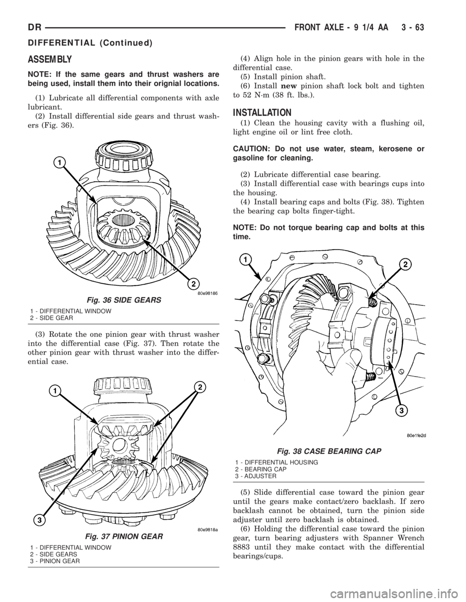
ers (Fig. 36).
(3) Rotate the one pinion gear with thrust washer
into the differential case (Fig. 37). Then rotate the
other pinion gear with thrust washer into the differ-
ential case.(4) Align hole in the pinion gears with hole in the
differential case.
(5) Install pinion shaft.
(6) Installnewpinion shaft lock bolt and tighten
to 52 N´m (38 ft. lbs.).
INSTALLATION
(1) Clean the housing cavity with a flushing oil,
light engine oil or lint free cloth.
CAUTION: Do not use water, steam, kerosene or
gasoline for cleaning.
(2) Lubricate differential case bearing.
(3) Install differential case with bearings cups into
the housing.
(4) Install bearing caps and bolts (Fig. 38). Tighten
the bearing cap bolts finger-tight.
NOTE: Do not torque bearing cap and bolts at this
time.
(5) Slide differential case toward the pinion gear
until the gears make contact/zero backlash. If zero
backlash cannot be obtained, turn the pinion side
adjuster until zero backlash is obtained.
(6) Holding the differential case toward the pinion
gear, turn bearing adjusters with Spanner Wrench
8883 until they make contact with the differential
bearings/cups.
Fig. 36 SIDE GEARS
1 - DIFFERENTIAL WINDOW
2 - SIDE GEAR
Fig. 37 PINION GEAR
1 - DIFFERENTIAL WINDOW
2 - SIDE GEARS
3 - PINION GEAR
Fig. 38 CASE BEARING CAP
1 - DIFFERENTIAL HOUSING
2 - BEARING CAP
3 - ADJUSTER
DRFRONT AXLE - 9 1/4 AA 3 - 63
DIFFERENTIAL (Continued)
Page 189 of 2895

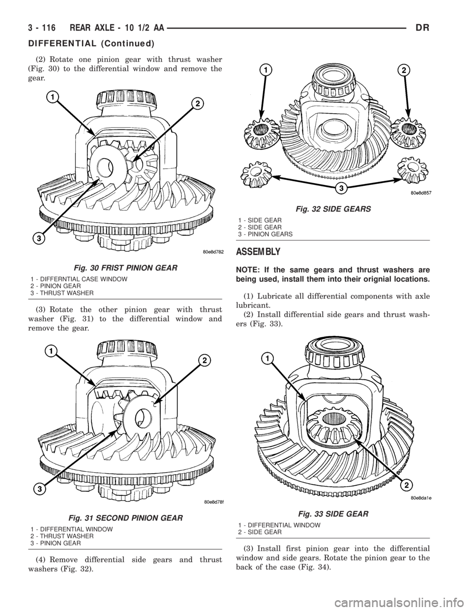
(2) Rotate one pinion gear with thrust washer
(Fig. 30) to the differential window and remove the
gear.
(3) Rotate the other pinion gear with thrust
washer (Fig. 31) to the differential window and
remove the gear.
(4) Remove differential side gears and thrust
washers (Fig. 32).
ASSEMBLY
NOTE: If the same gears and thrust washers are
being used, install them into their orignial locations.
(1) Lubricate all differential components with axle
lubricant.
(2) Install differential side gears and thrust wash-
ers (Fig. 33).
(3) Install first pinion gear into the differential
window and side gears. Rotate the pinion gear to the
back of the case (Fig. 34).Fig. 30 FRIST PINION GEAR
1 - DIFFERNTIAL CASE WINDOW
2 - PINION GEAR
3 - THRUST WASHER
Fig. 31 SECOND PINION GEAR
1 - DIFFERENTIAL WINDOW
2 - THRUST WASHER
3 - PINION GEAR
Fig. 32 SIDE GEARS
1 - SIDE GEAR
2 - SIDE GEAR
3 - PINION GEARS
Fig. 33 SIDE GEAR
1 - DIFFERENTIAL WINDOW
2 - SIDE GEAR
3 - 116 REAR AXLE - 10 1/2 AADR
DIFFERENTIAL (Continued)
Page 190 of 2895

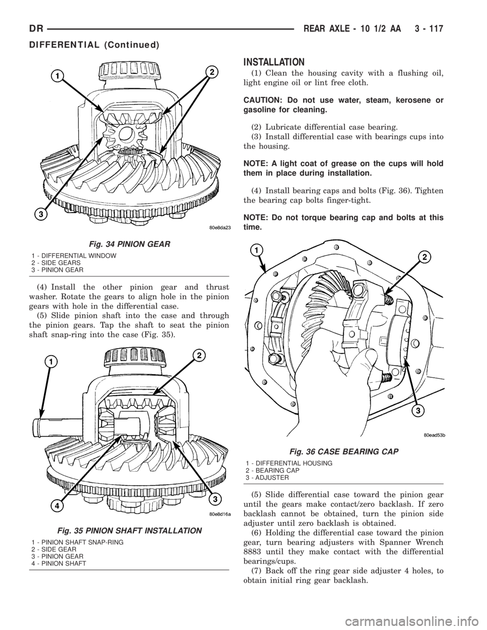
(4) Install the other pinion gear and thrust
washer. Rotate the gears to align hole in the pinion
gears with hole in the differential case.
(5) Slide pinion shaft into the case and through
the pinion gears. Tap the shaft to seat the pinion
shaft snap-ring into the case (Fig. 35).
INSTALLATION
(1) Clean the housing cavity with a flushing oil,
light engine oil or lint free cloth.
CAUTION: Do not use water, steam, kerosene or
gasoline for cleaning.
(2) Lubricate differential case bearing.
(3) Install differential case with bearings cups into
the housing.
NOTE: A light coat of grease on the cups will hold
them in place during installation.
(4) Install bearing caps and bolts (Fig. 36). Tighten
the bearing cap bolts finger-tight.
NOTE: Do not torque bearing cap and bolts at this
time.
(5) Slide differential case toward the pinion gear
until the gears make contact/zero backlash. If zero
backlash cannot be obtained, turn the pinion side
adjuster until zero backlash is obtained.
(6) Holding the differential case toward the pinion
gear, turn bearing adjusters with Spanner Wrench
8883 until they make contact with the differential
bearings/cups.
(7) Back off the ring gear side adjuster 4 holes, to
obtain initial ring gear backlash.
Fig. 34 PINION GEAR
1 - DIFFERENTIAL WINDOW
2 - SIDE GEARS
3 - PINION GEAR
Fig. 35 PINION SHAFT INSTALLATION
1 - PINION SHAFT SNAP-RING
2 - SIDE GEAR
3 - PINION GEAR
4 - PINION SHAFT
Fig. 36 CASE BEARING CAP
1 - DIFFERENTIAL HOUSING
2 - BEARING CAP
3 - ADJUSTER
DRREAR AXLE - 10 1/2 AA 3 - 117
DIFFERENTIAL (Continued)
Page 215 of 2895

REMOVAL
(1) Remove fill hole plug from the differential
housing cover.
(2) Remove differential housing cover and drain
the lubricant.
(3) Remove axle shafts.
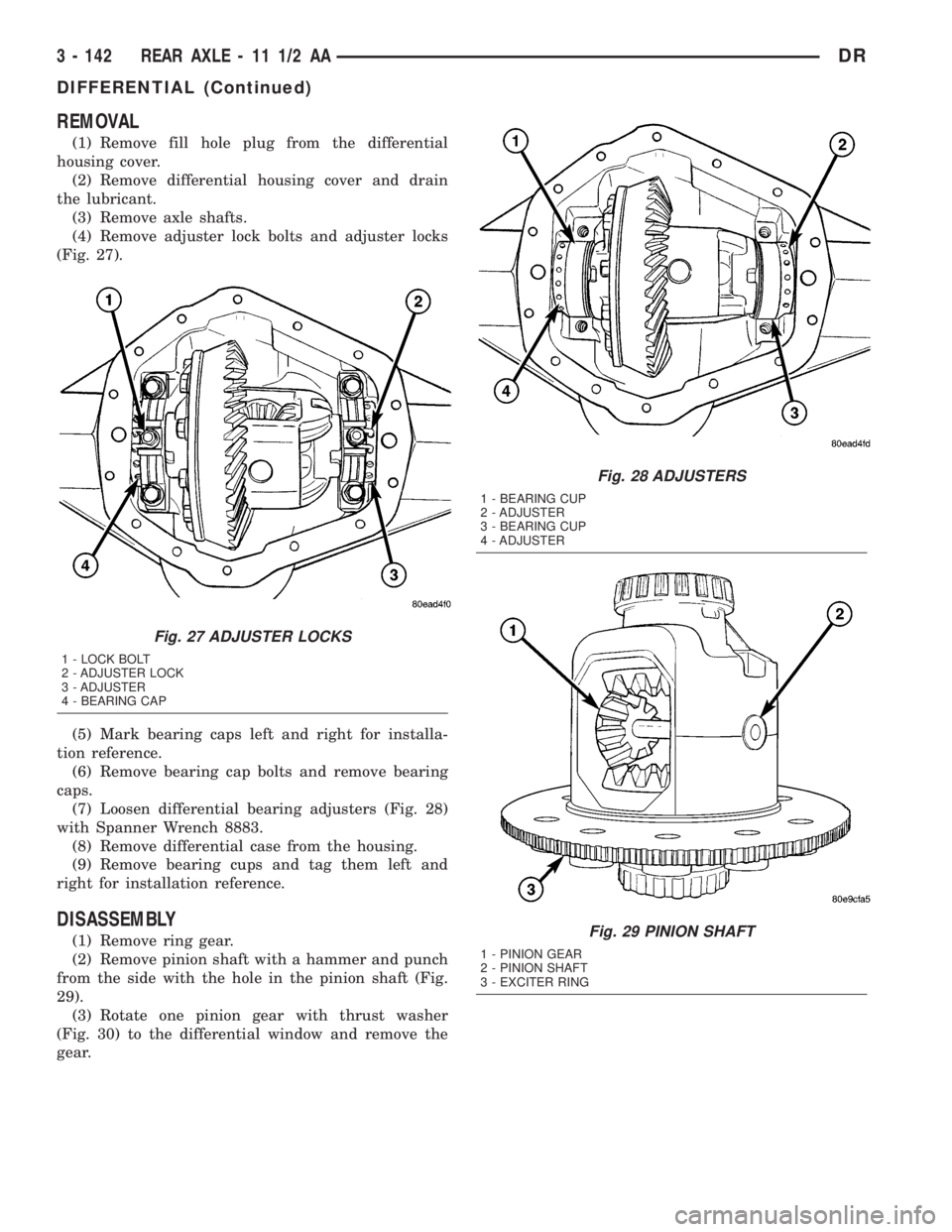
(4) Remove adjuster lock bolts and adjuster locks
(Fig. 27).
(5) Mark bearing caps left and right for installa-
tion reference.
(6) Remove bearing cap bolts and remove bearing
caps.
(7) Loosen differential bearing adjusters (Fig. 28)
with Spanner Wrench 8883.
(8) Remove differential case from the housing.
(9) Remove bearing cups and tag them left and
right for installation reference.
DISASSEMBLY
(1) Remove ring gear.
(2) Remove pinion shaft with a hammer and punch
from the side with the hole in the pinion shaft (Fig.
29).
(3) Rotate one pinion gear with thrust washer
(Fig. 30) to the differential window and remove the
gear.
Fig. 27 ADJUSTER LOCKS
1 - LOCK BOLT
2 - ADJUSTER LOCK
3 - ADJUSTER
4 - BEARING CAP
Fig. 28 ADJUSTERS
1 - BEARING CUP
2 - ADJUSTER
3 - BEARING CUP
4 - ADJUSTER
Fig. 29 PINION SHAFT
1 - PINION GEAR
2 - PINION SHAFT
3 - EXCITER RING
3 - 142 REAR AXLE - 11 1/2 AADR
DIFFERENTIAL (Continued)