2003 DODGE RAM electrical
[x] Cancel search: electricalPage 1719 of 2895
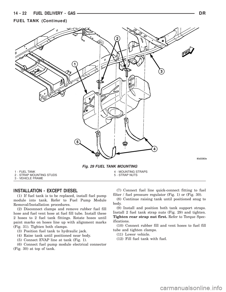
INSTALLATION - EXCEPT DIESEL
(1) If fuel tank is to be replaced, install fuel pump
module into tank. Refer to Fuel Pump Module
Removal/Installation procedures.
(2) Disconnect clamps and remove rubber fuel fill
hose and fuel vent hose at fuel fill tube. Install these
2 hoses to 2 fuel tank fittings. Rotate hoses until
paint marks on hoses line up with alignment marks
(Fig. 31). Tighten both clamps.
(3) Position fuel tank to hydraulic jack.
(4) Raise tank until positioned near body.
(5) Connect EVAP line at tank (Fig. 1).
(6) Connect fuel pump module electrical connector
(Fig. 30) at top of tank.(7) Connect fuel line quick-connect fitting to fuel
filter / fuel pressure regulator (Fig. 1) or (Fig. 30).
(8) Continue raising tank until positioned snug to
body.
(9) Install and position both tank support straps.
Install 2 fuel tank strap nuts (Fig. 29) and tighten.
Tighten rear strap nut first.Refer to Torque Spec-
ifications.
(10) Connect rubber fill and vent hoses to fuel fill
tube and tighten clamps.
(11) Lower vehicle.
(12) Fill fuel tank with fuel.
Fig. 29 FUEL TANK MOUNTING
1 - FUEL TANK
2 - STRAP MOUNTING STUDS
3 - VEHICLE FRAME4 - MOUNTING STRAPS
5 - STRAP NUTS
14 - 22 FUEL DELIVERY - GASDR
FUEL TANK (Continued)
Page 1722 of 2895
ACCELERATOR PEDAL
POSITION SENSOR
DESCRIPTION
The Accelerator Pedal Position Sensor (APPS)
assembly is located under the vehicle battery tray. A
cable connects the assembly to the accelerator pedal.
A plastic cover with a movable door is used to cover
the assembly.
The APPS is used only with the 5.7L V-8 engine.
OPERATION
The Accelerator Pedal Position Sensor (APPS) is a
linear potentiometer. It provides the Powertrain Con-
trol Module (PCM) with a DC voltage signal propor-
tional to the angle, or position of the accelerator
pedal. The APPS signal is translated (along with
other sensors) to place the throttle plate (within the
throttle body) to a pre-determined position.
A mechanical cable is used between the accelerator
pedal and the APPS assembly. Although a cable is
used between the pedal and APPS, a mechanical
cable is not used at the throttle body. Throttle plate
position is electrically determined.
REMOVAL
The APPS is serviced (replaced) as one assembly
including the sensor, plastic housing and cable. The
APPS assembly is located under the vehicle battery
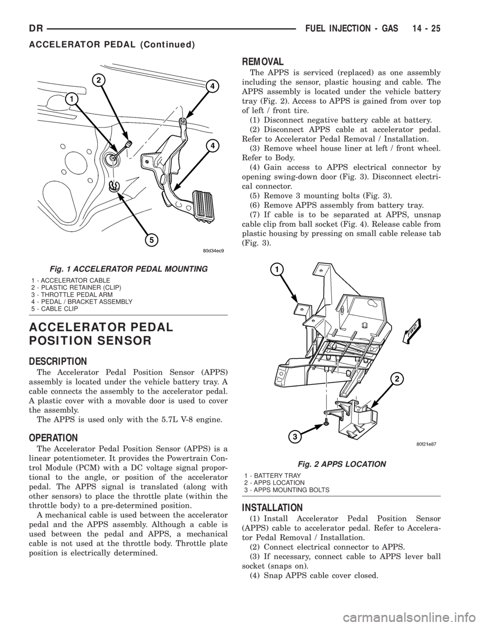
tray (Fig. 2). Access to APPS is gained from over top
of left / front tire.
(1) Disconnect negative battery cable at battery.
(2) Disconnect APPS cable at accelerator pedal.
Refer to Accelerator Pedal Removal / Installation.
(3) Remove wheel house liner at left / front wheel.
Refer to Body.
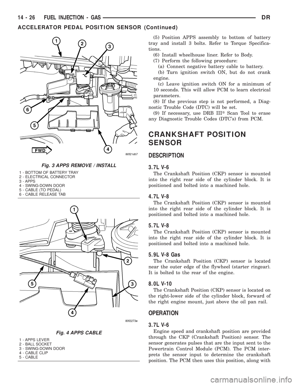
(4) Gain access to APPS electrical connector by
opening swing-down door (Fig. 3). Disconnect electri-
cal connector.
(5) Remove 3 mounting bolts (Fig. 3).
(6) Remove APPS assembly from battery tray.
(7) If cable is to be separated at APPS, unsnap
cable clip from ball socket (Fig. 4). Release cable from
plastic housing by pressing on small cable release tab
(Fig. 3).
INSTALLATION
(1) Install Accelerator Pedal Position Sensor
(APPS) cable to accelerator pedal. Refer to Accelera-
tor Pedal Removal / Installation.
(2) Connect electrical connector to APPS.
(3) If necessary, connect cable to APPS lever ball
socket (snaps on).
(4) Snap APPS cable cover closed.
Fig. 1 ACCELERATOR PEDAL MOUNTING
1 - ACCELERATOR CABLE
2 - PLASTIC RETAINER (CLIP)
3 - THROTTLE PEDAL ARM
4 - PEDAL / BRACKET ASSEMBLY
5 - CABLE CLIP
Fig. 2 APPS LOCATION
1 - BATTERY TRAY
2 - APPS LOCATION
3 - APPS MOUNTING BOLTS
DRFUEL INJECTION - GAS 14 - 25
ACCELERATOR PEDAL (Continued)
Page 1723 of 2895
(5) Position APPS assembly to bottom of battery
tray and install 3 bolts. Refer to Torque Specifica-
tions.
(6) Install wheelhouse liner. Refer to Body.
(7) Perform the following procedure:
(a) Connect negative battery cable to battery.
(b) Turn ignition switch ON, but do not crank
engine.
(c) Leave ignition switch ON for a minimum of
10 seconds. This will allow PCM to learn electrical
parameters.
(8) If the previous step is not performed, a Diag-
nostic Trouble Code (DTC) will be set.
(9) If necessary, use DRB IIItScan Tool to erase
any Diagnostic Trouble Codes (DTC's) from PCM.
CRANKSHAFT POSITION
SENSOR
DESCRIPTION
3.7L V-6
The Crankshaft Position (CKP) sensor is mounted
into the right rear side of the cylinder block. It is
positioned and bolted into a machined hole.
4.7L V-8
The Crankshaft Position (CKP) sensor is mounted
into the right rear side of the cylinder block. It is
positioned and bolted into a machined hole.
5.7L V-8
The Crankshaft Position (CKP) sensor is mounted
into the right rear side of the cylinder block. It is
positioned and bolted into a machined hole.
5.9L V-8 Gas
The Crankshaft Position (CKP) sensor is located
near the outer edge of the flywheel (starter ringear).
It is bolted to the rear of the engine.
8.0L V-10
The Crankshaft Position (CKP) sensor is located on
the right-lower side of the cylinder block, forward of
the right engine mount, just above the oil pan rail.
OPERATION
3.7L V-6
Engine speed and crankshaft position are provided
through the CKP (Crankshaft Position) sensor. The
sensor generates pulses that are the input sent to the
Powertrain Control Module (PCM). The PCM inter-
prets the sensor input to determine the crankshaft
position. The PCM then uses this position, along with
Fig. 3 APPS REMOVE / INSTALL
1 - BOTTOM OF BATTERY TRAY
2 - ELECTRICAL CONNECTOR
3 - APPS
4 - SWING-DOWN DOOR
5 - CABLE (TO PEDAL)
6 - CABLE RELEASE TAB
Fig. 4 APPS CABLE
1 - APPS LEVER
2 - BALL SOCKET
3 - SWING-DOWN DOOR
4 - CABLE CLIP
5 - CABLE
14 - 26 FUEL INJECTION - GASDR
ACCELERATOR PEDAL POSITION SENSOR (Continued)
Page 1726 of 2895
REMOVAL
3.7L V-6
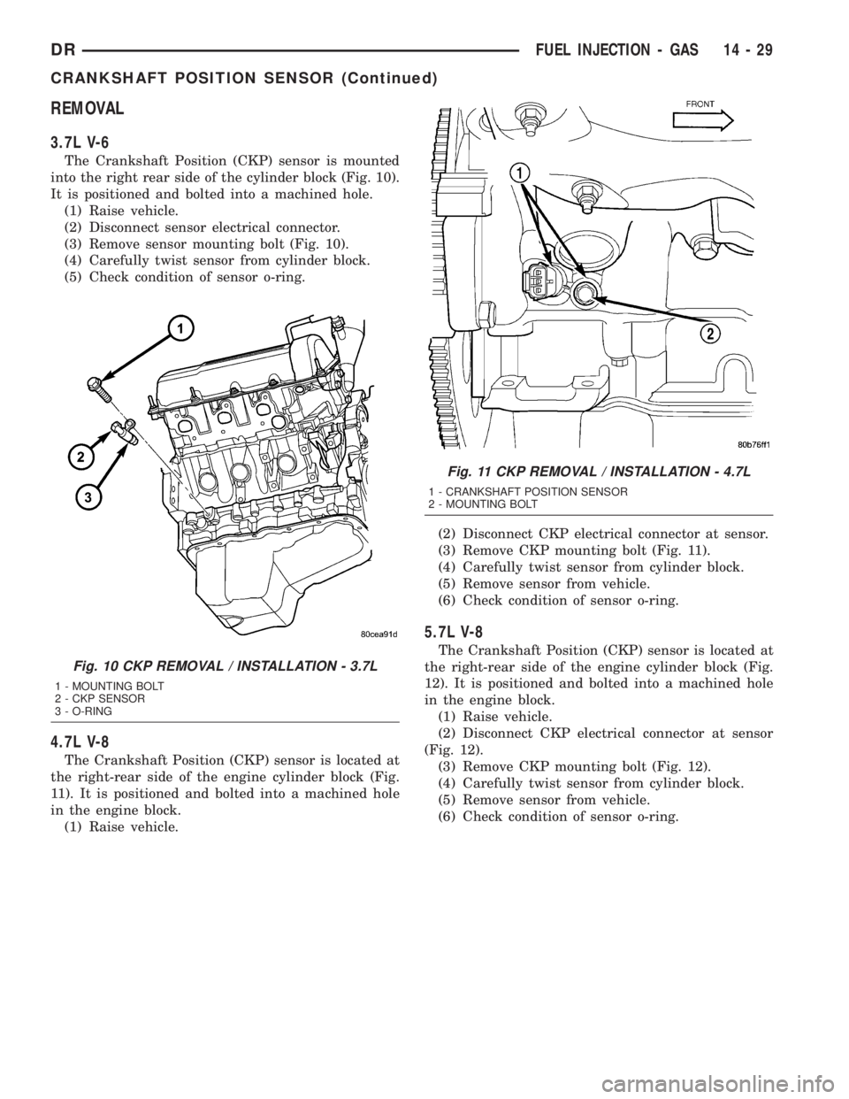
The Crankshaft Position (CKP) sensor is mounted
into the right rear side of the cylinder block (Fig. 10).
It is positioned and bolted into a machined hole.
(1) Raise vehicle.
(2) Disconnect sensor electrical connector.
(3) Remove sensor mounting bolt (Fig. 10).
(4) Carefully twist sensor from cylinder block.
(5) Check condition of sensor o-ring.
4.7L V-8
The Crankshaft Position (CKP) sensor is located at
the right-rear side of the engine cylinder block (Fig.
11). It is positioned and bolted into a machined hole
in the engine block.
(1) Raise vehicle.(2) Disconnect CKP electrical connector at sensor.
(3) Remove CKP mounting bolt (Fig. 11).
(4) Carefully twist sensor from cylinder block.
(5) Remove sensor from vehicle.
(6) Check condition of sensor o-ring.
5.7L V-8
The Crankshaft Position (CKP) sensor is located at
the right-rear side of the engine cylinder block (Fig.
12). It is positioned and bolted into a machined hole
in the engine block.
(1) Raise vehicle.
(2) Disconnect CKP electrical connector at sensor
(Fig. 12).
(3) Remove CKP mounting bolt (Fig. 12).
(4) Carefully twist sensor from cylinder block.
(5) Remove sensor from vehicle.
(6) Check condition of sensor o-ring.
Fig. 10 CKP REMOVAL / INSTALLATION - 3.7L
1 - MOUNTING BOLT
2 - CKP SENSOR
3 - O-RING
Fig. 11 CKP REMOVAL / INSTALLATION - 4.7L
1 - CRANKSHAFT POSITION SENSOR
2 - MOUNTING BOLT
DRFUEL INJECTION - GAS 14 - 29
CRANKSHAFT POSITION SENSOR (Continued)
Page 1728 of 2895
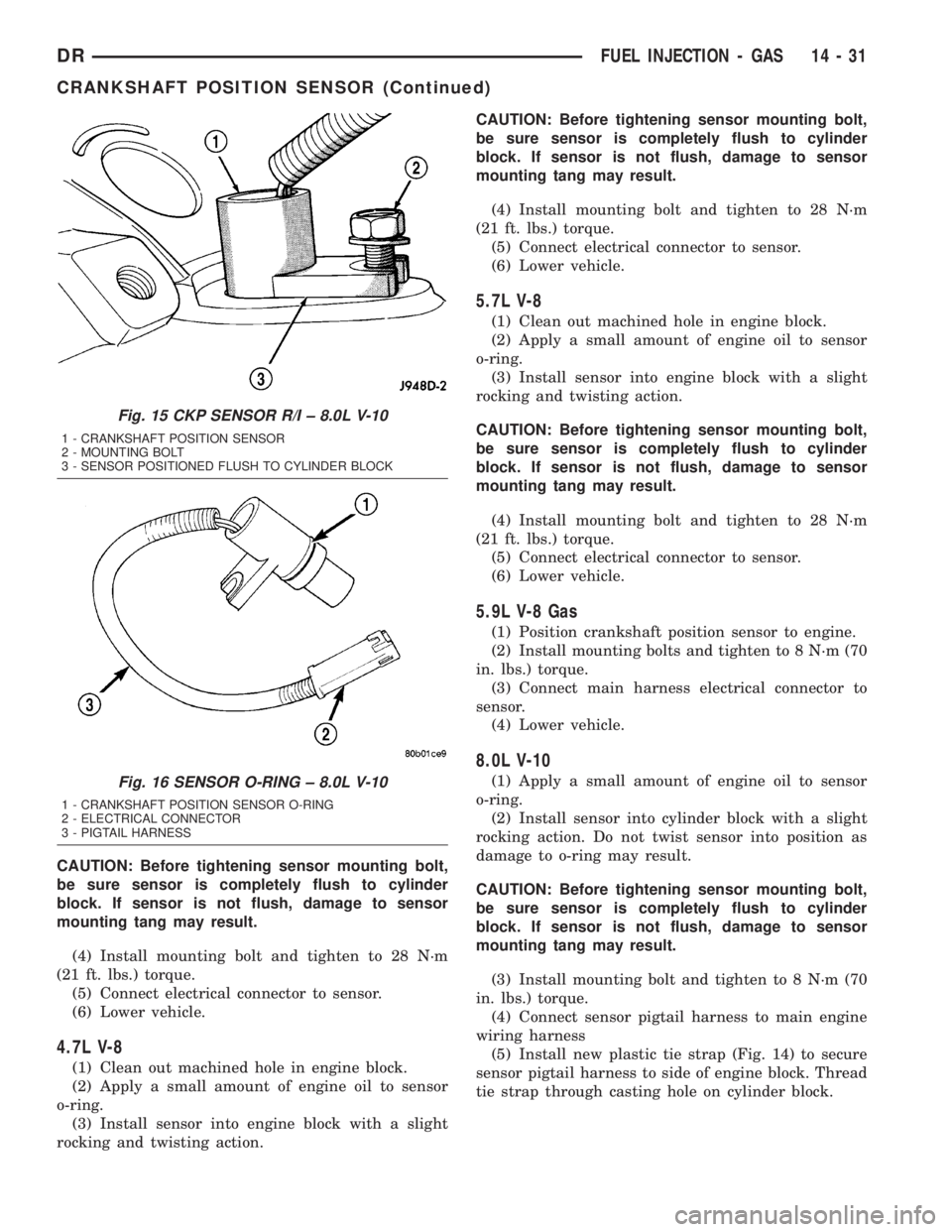
CAUTION: Before tightening sensor mounting bolt,
be sure sensor is completely flush to cylinder
block. If sensor is not flush, damage to sensor
mounting tang may result.
(4) Install mounting bolt and tighten to 28 N´m
(21 ft. lbs.) torque.
(5) Connect electrical connector to sensor.
(6) Lower vehicle.
4.7L V-8
(1) Clean out machined hole in engine block.
(2) Apply a small amount of engine oil to sensor
o-ring.
(3) Install sensor into engine block with a slight
rocking and twisting action.CAUTION: Before tightening sensor mounting bolt,
be sure sensor is completely flush to cylinder
block. If sensor is not flush, damage to sensor
mounting tang may result.
(4) Install mounting bolt and tighten to 28 N´m
(21 ft. lbs.) torque.
(5) Connect electrical connector to sensor.
(6) Lower vehicle.
5.7L V-8
(1) Clean out machined hole in engine block.
(2) Apply a small amount of engine oil to sensor
o-ring.
(3) Install sensor into engine block with a slight
rocking and twisting action.
CAUTION: Before tightening sensor mounting bolt,
be sure sensor is completely flush to cylinder
block. If sensor is not flush, damage to sensor
mounting tang may result.
(4) Install mounting bolt and tighten to 28 N´m
(21 ft. lbs.) torque.
(5) Connect electrical connector to sensor.
(6) Lower vehicle.
5.9L V-8 Gas
(1) Position crankshaft position sensor to engine.
(2) Install mounting bolts and tighten to 8 N´m (70
in. lbs.) torque.
(3) Connect main harness electrical connector to
sensor.
(4) Lower vehicle.
8.0L V-10
(1) Apply a small amount of engine oil to sensor
o-ring.
(2) Install sensor into cylinder block with a slight
rocking action. Do not twist sensor into position as
damage to o-ring may result.
CAUTION: Before tightening sensor mounting bolt,
be sure sensor is completely flush to cylinder
block. If sensor is not flush, damage to sensor
mounting tang may result.
(3) Install mounting bolt and tighten to 8 N´m (70
in. lbs.) torque.
(4) Connect sensor pigtail harness to main engine
wiring harness
(5) Install new plastic tie strap (Fig. 14) to secure
sensor pigtail harness to side of engine block. Thread
tie strap through casting hole on cylinder block.
Fig. 15 CKP SENSOR R/I ± 8.0L V-10
1 - CRANKSHAFT POSITION SENSOR
2 - MOUNTING BOLT
3 - SENSOR POSITIONED FLUSH TO CYLINDER BLOCK
Fig. 16 SENSOR O-RING ± 8.0L V-10
1 - CRANKSHAFT POSITION SENSOR O-RING
2 - ELECTRICAL CONNECTOR
3 - PIGTAIL HARNESS
DRFUEL INJECTION - GAS 14 - 31
CRANKSHAFT POSITION SENSOR (Continued)
Page 1729 of 2895
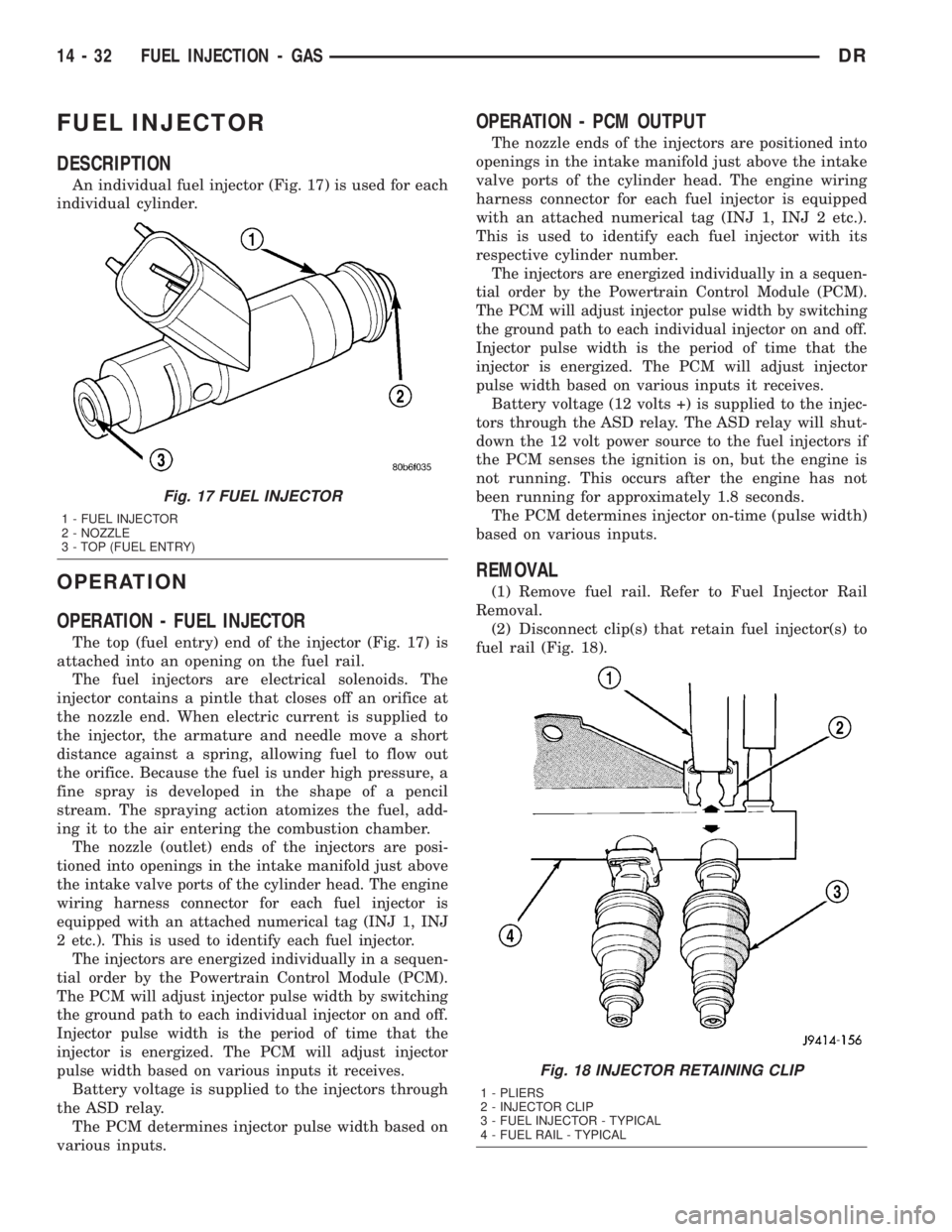
FUEL INJECTOR
DESCRIPTION
An individual fuel injector (Fig. 17) is used for each
individual cylinder.
OPERATION
OPERATION - FUEL INJECTOR
The top (fuel entry) end of the injector (Fig. 17) is
attached into an opening on the fuel rail.
The fuel injectors are electrical solenoids. The
injector contains a pintle that closes off an orifice at
the nozzle end. When electric current is supplied to
the injector, the armature and needle move a short
distance against a spring, allowing fuel to flow out
the orifice. Because the fuel is under high pressure, a
fine spray is developed in the shape of a pencil
stream. The spraying action atomizes the fuel, add-
ing it to the air entering the combustion chamber.
The nozzle (outlet) ends of the injectors are posi-
tioned into openings in the intake manifold just above
the intake valve ports of the cylinder head. The engine
wiring harness connector for each fuel injector is
equipped with an attached numerical tag (INJ 1, INJ
2 etc.). This is used to identify each fuel injector.
The injectors are energized individually in a sequen-
tial order by the Powertrain Control Module (PCM).
The PCM will adjust injector pulse width by switching
the ground path to each individual injector on and off.
Injector pulse width is the period of time that the
injector is energized. The PCM will adjust injector
pulse width based on various inputs it receives.
Battery voltage is supplied to the injectors through
the ASD relay.
The PCM determines injector pulse width based on
various inputs.
OPERATION - PCM OUTPUT
The nozzle ends of the injectors are positioned into
openings in the intake manifold just above the intake
valve ports of the cylinder head. The engine wiring
harness connector for each fuel injector is equipped
with an attached numerical tag (INJ 1, INJ 2 etc.).
This is used to identify each fuel injector with its
respective cylinder number.
The injectors are energized individually in a sequen-
tial order by the Powertrain Control Module (PCM).
The PCM will adjust injector pulse width by switching
the ground path to each individual injector on and off.
Injector pulse width is the period of time that the
injector is energized. The PCM will adjust injector
pulse width based on various inputs it receives.
Battery voltage (12 volts +) is supplied to the injec-
tors through the ASD relay. The ASD relay will shut-
down the 12 volt power source to the fuel injectors if
the PCM senses the ignition is on, but the engine is
not running. This occurs after the engine has not
been running for approximately 1.8 seconds.
The PCM determines injector on-time (pulse width)
based on various inputs.
REMOVAL
(1) Remove fuel rail. Refer to Fuel Injector Rail
Removal.
(2) Disconnect clip(s) that retain fuel injector(s) to
fuel rail (Fig. 18).
Fig. 17 FUEL INJECTOR
1 - FUEL INJECTOR
2 - NOZZLE
3 - TOP (FUEL ENTRY)
Fig. 18 INJECTOR RETAINING CLIP
1 - PLIERS
2 - INJECTOR CLIP
3 - FUEL INJECTOR - TYPICAL
4 - FUEL RAIL - TYPICAL
14 - 32 FUEL INJECTION - GASDR
Page 1731 of 2895
The IAC motor has 4 wires with 4 circuits. Two of
the wires are for 12 volts and ground to supply elec-
trical current to the motor windings to operate the
stepper motor in one direction. The other 2 wires are
also for 12 volts and ground to supply electrical cur-
rent to operate the stepper motor in the opposite
direction.
To make the IAC go in the opposite direction, the
PCM just reverses polarity on both windings. If only
1 wire is open, the IAC can only be moved 1 step
(increment) in either direction. To keep the IAC
motor in position when no movement is needed, the
PCM will energize both windings at the same time.
This locks the IAC motor in place.
In the IAC motor system, the PCM will count
every step that the motor is moved. This allows the
PCM to determine the motor pintle position. If the
memory is cleared, the PCM no longer knows the
position of the pintle. So at the first key ON, the
PCM drives the IAC motor closed, regardless of
where it was before. This zeros the counter. From
this point the PCM will back out the IAC motor and
keep track of its position again.
When engine rpm is above idle speed, the IAC is
used for the following:
²Off-idle dashpot (throttle blade will close quickly
but idle speed will not stop quickly)
²Deceleration air flow control
²A/C compressor load control (also opens the pas-
sage slightly before the compressor is engaged so
that the engine rpm does not dip down when the
compressor engages)
²Power steering load control
The PCM can control polarity of the circuit to con-
trol direction of the stepper motor.
IAC Stepper Motor Program:The PCM is also
equipped with a memory program that records the
number of steps the IAC stepper motor most recently
advanced to during a certain set of parameters. For
example: The PCM was attempting to maintain a
1000 rpm target during a cold start-up cycle. The last
recorded number of steps for that may have been
125. That value would be recorded in the memory
cell so that the next time the PCM recognizes the
identical conditions, the PCM recalls that 125 steps
were required to maintain the target. This program
allows for greater customer satisfaction due to
greater control of engine idle.
Another function of the memory program, which
occurs when the power steering switch (if equipped),
or the A/C request circuit, requires that the IAC step-
per motor control engine rpm, is the recording of the
last targeted steps into the memory cell. The PCM
can anticipate A/C compressor loads. This is accom-
plished by delaying compressor operation for approx-
imately 0.5 seconds until the PCM moves the IACstepper motor to the recorded steps that were loaded
into the memory cell. Using this program helps elim-
inate idle-quality changes as loads change. Finally,
the PCM incorporates a9No-Load9engine speed lim-
iter of approximately 1800 - 2000 rpm, when it rec-
ognizes that the TPS is indicating an idle signal and
IAC motor cannot maintain engine idle.
A (factory adjusted) set screw is used to mechani-
cally limit the position of the throttle body throttle
plate.Never attempt to adjust the engine idle
speed using this screw.All idle speed functions are
controlled by the IAC motor through the PCM.
REMOVAL
3.7L V-6
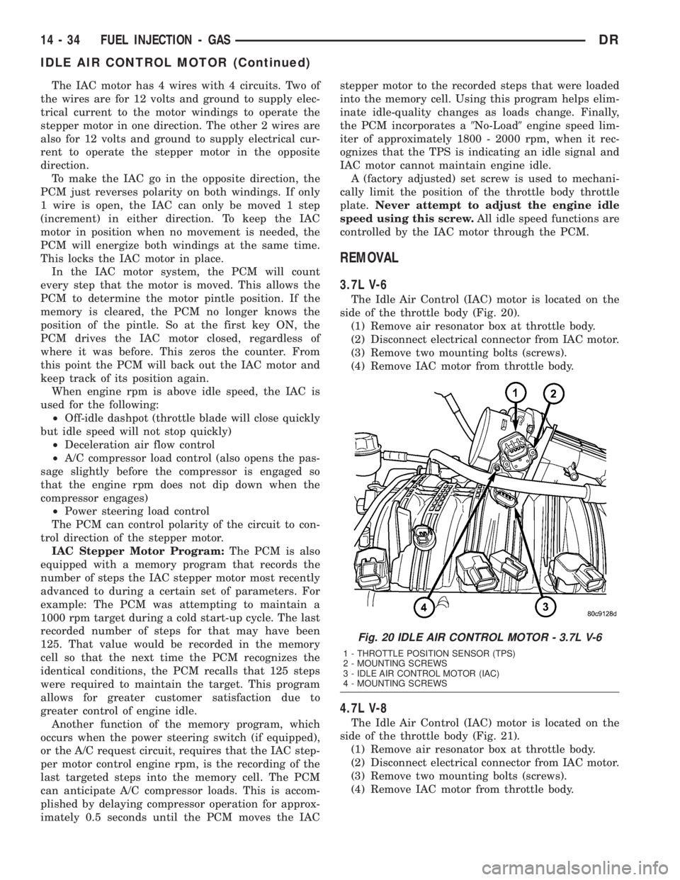
The Idle Air Control (IAC) motor is located on the
side of the throttle body (Fig. 20).
(1) Remove air resonator box at throttle body.
(2) Disconnect electrical connector from IAC motor.
(3) Remove two mounting bolts (screws).
(4) Remove IAC motor from throttle body.
4.7L V-8
The Idle Air Control (IAC) motor is located on the
side of the throttle body (Fig. 21).
(1) Remove air resonator box at throttle body.
(2) Disconnect electrical connector from IAC motor.
(3) Remove two mounting bolts (screws).
(4) Remove IAC motor from throttle body.
Fig. 20 IDLE AIR CONTROL MOTOR - 3.7L V-6
1 - THROTTLE POSITION SENSOR (TPS)
2 - MOUNTING SCREWS
3 - IDLE AIR CONTROL MOTOR (IAC)
4 - MOUNTING SCREWS
14 - 34 FUEL INJECTION - GASDR
IDLE AIR CONTROL MOTOR (Continued)
Page 1732 of 2895
5.7L V-8
The IAC motor is not serviceable on the 5.7L V-8
engine.
5.9L V-8
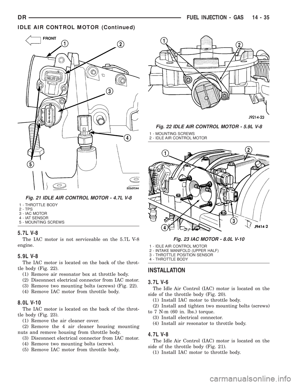
The IAC motor is located on the back of the throt-
tle body (Fig. 22).
(1) Remove air resonator box at throttle body.
(2) Disconnect electrical connector from IAC motor.
(3) Remove two mounting bolts (screws) (Fig. 22).
(4) Remove IAC motor from throttle body.
8.0L V-10
The IAC motor is located on the back of the throt-
tle body (Fig. 23).
(1) Remove the air cleaner cover.
(2) Remove the 4 air cleaner housing mounting
nuts and remove housing from throttle body.
(3) Disconnect electrical connector from IAC motor.
(4) Remove two mounting bolts (screw).
(5) Remove IAC motor from throttle body.
INSTALLATION
3.7L V-6
The Idle Air Control (IAC) motor is located on the
side of the throttle body (Fig. 20).
(1) Install IAC motor to throttle body.
(2) Install and tighten two mounting bolts (screws)
to 7 N´m (60 in. lbs.) torque.
(3) Install electrical connector.
(4) Install air resonator to throttle body.
4.7L V-8
The Idle Air Control (IAC) motor is located on the
side of the throttle body (Fig. 21).
(1) Install IAC motor to throttle body.
Fig. 21 IDLE AIR CONTROL MOTOR - 4.7L V-8
1 - THROTTLE BODY
2 - TPS
3 - IAC MOTOR
4 - IAT SENSOR
5 - MOUNTING SCREWS
Fig. 22 IDLE AIR CONTROL MOTOR - 5.9L V-8
1 - MOUNTING SCREWS
2 - IDLE AIR CONTROL MOTOR
Fig. 23 IAC MOTOR - 8.0L V-10
1 - IDLE AIR CONTROL MOTOR
2 - INTAKE MANIFOLD (UPPER HALF)
3 - THROTTLE POSITION SENSOR
4 - THROTTLE BODY
DRFUEL INJECTION - GAS 14 - 35
IDLE AIR CONTROL MOTOR (Continued)