2003 DODGE RAM electrical
[x] Cancel search: electricalPage 1773 of 2895
OPERATION
The purpose of the fuel transfer pump is to supply
(transfer) a low-pressure fuel source:fromthe fuel
tank,throughthe fuel filter/water separator andto
the fuel injection pump. Here, the low-pressure is
raised to a high-pressure by the fuel injection pump
for operation of the high-pressure fuel injectors.
Check valves within the pump, control direction of
fuel flow and prevent fuel bleed-back during engine
shut down.
Maximum current flow to the pump is 5 amperes.
With the engine running, the pump has a 100 per-
cent duty-cycle with a minimum pressure of 11.5 psi.
The transfer pump is self-priming: When the key is
first turned on (without cranking engine), the pump
will operate for approximately 1/2 second and then
shut off. The pump will also operate for up to 25 sec-
onds after the starter is engaged, and then disen-
gaged and the engine is not running. The pump
shuts off immediately if the key is on and the engine
stops running.
The fuel volume of the transfer pump will always
provide more fuel than the fuel injection pump
requires. Excess fuel is returned from the injection
pump through an overflow valve, and then back to
the fuel tank.
REMOVAL
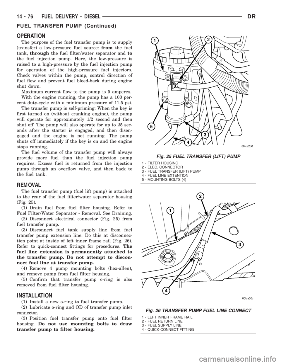
The fuel transfer pump (fuel lift pump) is attached
to the rear of the fuel filter/water separator housing
(Fig. 25).
(1) Drain fuel from fuel filter housing. Refer to
Fuel Filter/Water Separator - Removal. See Draining.
(2) Disconnect electrical connector (Fig. 25) from
fuel transfer pump.
(3) Disconnect fuel tank supply line from fuel
transfer pump extension line. Do this at disconnec-
tion point at inside of left inner frame rail (Fig. 26).
Refer to quick-connect fittings for procedures.The
fuel line extension is permanently attached to
the transfer pump. Do not attempt to discon-
nect fuel line at transfer pump.
(4) Remove 4 pump mounting bolts (hex-allen),
and remove pump from fuel filter housing.
(5) Confirm that transfer pump o-ring is also
removed from fuel filter housing.
INSTALLATION
(1) Install a new o-ring to fuel transfer pump.
(2) Lubricate o-ring and OD of transfer pump inlet
connector.
(3) Position fuel transfer pump onto fuel filter
housing.Do not use mounting bolts to draw
transfer pump to filter housing.
Fig. 25 FUEL TRANSFER (LIFT) PUMP
1 - FILTER HOUSING
2 - ELEC. CONNECTOR
3 - FUEL TRANSFER (LIFT) PUMP
4 - FUEL LINE EXTENTION
5 - MOUNTING BOLTS (4)
Fig. 26 TRANSFER PUMP FUEL LINE CONNECT
1 - LEFT INNER FRAME RAIL
2 - FUEL RETURN LINE
3 - FUEL SUPPLY LINE
4 - QUICK-CONNECT FITTING
14 - 76 FUEL DELIVERY - DIESELDR
FUEL TRANSFER PUMP (Continued)
Page 1774 of 2895
(4) Be sure pump is positioned flat to fuel filter
housing. Install mounting bolts and evenly tighten to
7 N´m (61 in. lbs.).
(5) Connect fuel line extension at fuel supply line.
(6) Connect electrical connector to pump.
(7)Prime System:Cycle key to actuate transfer
pump or use DRB II Scan Tool to actuate transfer
pump. Check for leaks.
(8) Operate engine and check for fuel leaks.
CASCADE OVERFLOW VALVE
DESCRIPTION
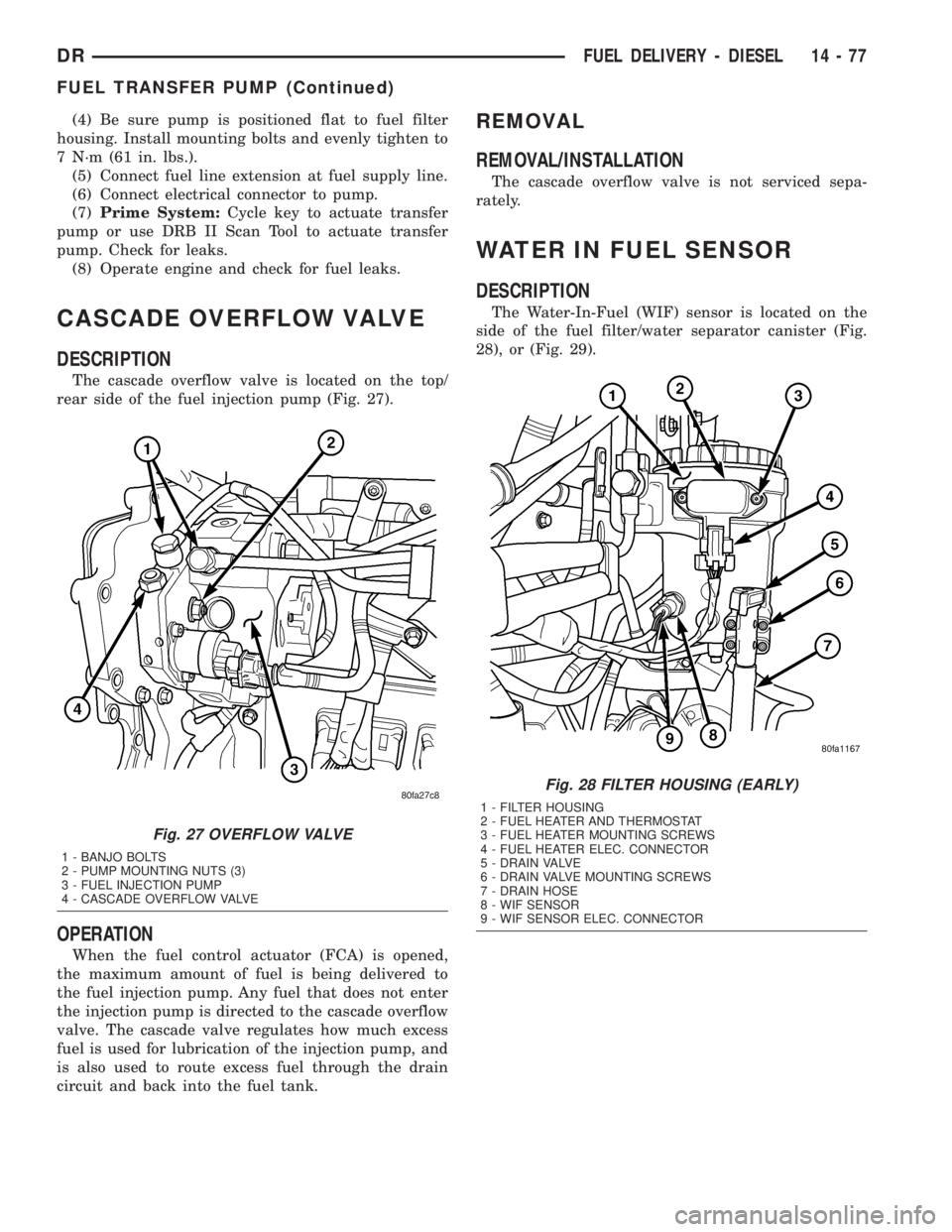
The cascade overflow valve is located on the top/
rear side of the fuel injection pump (Fig. 27).
OPERATION
When the fuel control actuator (FCA) is opened,
the maximum amount of fuel is being delivered to
the fuel injection pump. Any fuel that does not enter
the injection pump is directed to the cascade overflow
valve. The cascade valve regulates how much excess
fuel is used for lubrication of the injection pump, and
is also used to route excess fuel through the drain
circuit and back into the fuel tank.
REMOVAL
REMOVAL/INSTALLATION
The cascade overflow valve is not serviced sepa-
rately.
WATER IN FUEL SENSOR
DESCRIPTION
The Water-In-Fuel (WIF) sensor is located on the
side of the fuel filter/water separator canister (Fig.
28), or (Fig. 29).
Fig. 27 OVERFLOW VALVE
1 - BANJO BOLTS
2 - PUMP MOUNTING NUTS (3)
3 - FUEL INJECTION PUMP
4 - CASCADE OVERFLOW VALVE
Fig. 28 FILTER HOUSING (EARLY)
1 - FILTER HOUSING
2 - FUEL HEATER AND THERMOSTAT
3 - FUEL HEATER MOUNTING SCREWS
4 - FUEL HEATER ELEC. CONNECTOR
5 - DRAIN VALVE
6 - DRAIN VALVE MOUNTING SCREWS
7 - DRAIN HOSE
8 - WIF SENSOR
9 - WIF SENSOR ELEC. CONNECTOR
DRFUEL DELIVERY - DIESEL 14 - 77
FUEL TRANSFER PUMP (Continued)
Page 1777 of 2895
CAUTION: Do not attempt to remove sensor from
its mounting bracket as electronic calibration will
be destroyed (sensor-to-bracket mounting screws
are permanently attached). Two accelerator lever
set screws (Fig. 3) are used to position lever. Do
not attempt to alter positions of these set screws as
electronic calibration will be destroyed.
(1) Disconnect both negative battery cables at both
batteries.
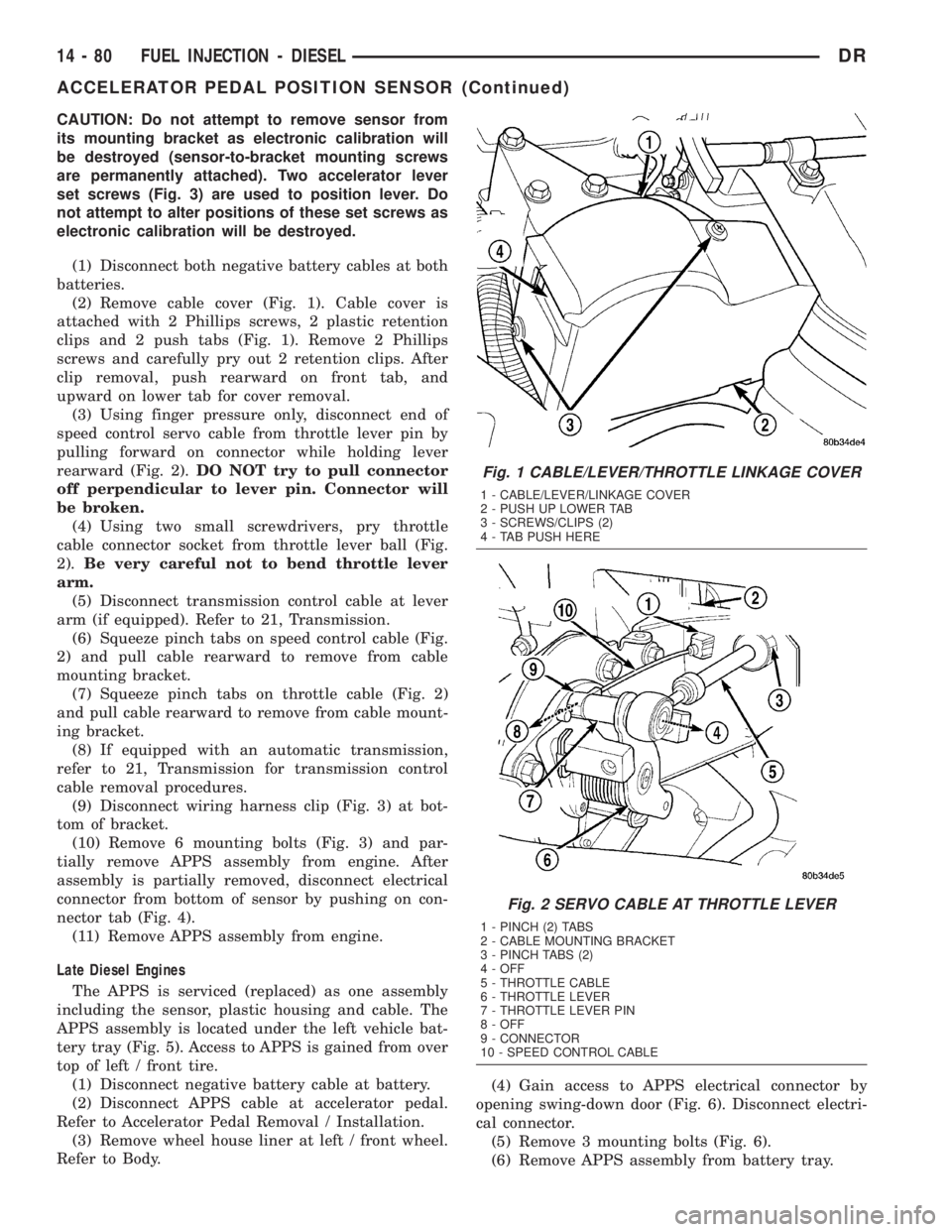
(2) Remove cable cover (Fig. 1). Cable cover is
attached with 2 Phillips screws, 2 plastic retention
clips and 2 push tabs (Fig. 1). Remove 2 Phillips
screws and carefully pry out 2 retention clips. After
clip removal, push rearward on front tab, and
upward on lower tab for cover removal.
(3) Using finger pressure only, disconnect end of
speed control servo cable from throttle lever pin by
pulling forward on connector while holding lever
rearward (Fig. 2).DO NOT try to pull connector
off perpendicular to lever pin. Connector will
be broken.
(4) Using two small screwdrivers, pry throttle
cable connector socket from throttle lever ball (Fig.
2).Be very careful not to bend throttle lever
arm.
(5) Disconnect transmission control cable at lever
arm (if equipped). Refer to 21, Transmission.
(6) Squeeze pinch tabs on speed control cable (Fig.
2) and pull cable rearward to remove from cable
mounting bracket.
(7) Squeeze pinch tabs on throttle cable (Fig. 2)
and pull cable rearward to remove from cable mount-
ing bracket.
(8) If equipped with an automatic transmission,
refer to 21, Transmission for transmission control
cable removal procedures.
(9) Disconnect wiring harness clip (Fig. 3) at bot-
tom of bracket.
(10) Remove 6 mounting bolts (Fig. 3) and par-
tially remove APPS assembly from engine. After
assembly is partially removed, disconnect electrical
connector from bottom of sensor by pushing on con-
nector tab (Fig. 4).
(11) Remove APPS assembly from engine.
Late Diesel Engines
The APPS is serviced (replaced) as one assembly
including the sensor, plastic housing and cable. The
APPS assembly is located under the left vehicle bat-
tery tray (Fig. 5). Access to APPS is gained from over
top of left / front tire.
(1) Disconnect negative battery cable at battery.
(2) Disconnect APPS cable at accelerator pedal.
Refer to Accelerator Pedal Removal / Installation.
(3) Remove wheel house liner at left / front wheel.
Refer to Body.(4) Gain access to APPS electrical connector by
opening swing-down door (Fig. 6). Disconnect electri-
cal connector.
(5) Remove 3 mounting bolts (Fig. 6).
(6) Remove APPS assembly from battery tray.
Fig. 1 CABLE/LEVER/THROTTLE LINKAGE COVER
1 - CABLE/LEVER/LINKAGE COVER
2 - PUSH UP LOWER TAB
3 - SCREWS/CLIPS (2)
4 - TAB PUSH HERE
Fig. 2 SERVO CABLE AT THROTTLE LEVER
1 - PINCH (2) TABS
2 - CABLE MOUNTING BRACKET
3 - PINCH TABS (2)
4 - OFF
5 - THROTTLE CABLE
6 - THROTTLE LEVER
7 - THROTTLE LEVER PIN
8 - OFF
9 - CONNECTOR
10 - SPEED CONTROL CABLE
14 - 80 FUEL INJECTION - DIESELDR
ACCELERATOR PEDAL POSITION SENSOR (Continued)
Page 1778 of 2895
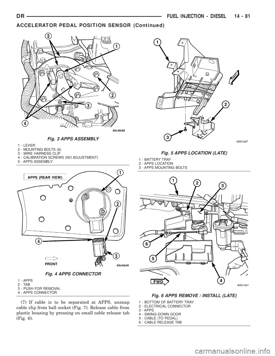
(7) If cable is to be separated at APPS, unsnap
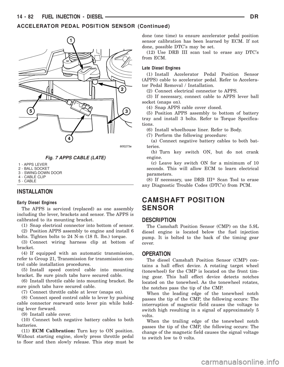
cable clip from ball socket (Fig. 7). Release cable from
plastic housing by pressing on small cable release tab
(Fig. 6).
Fig. 3 APPS ASSEMBLY
1 - LEVER
2 - MOUNTING BOLTS (6)
3 - WIRE HARNESS CLIP
4 - CALIBRATION SCREWS (NO ADJUSTMENT)
5 - APPS ASSEMBLY
Fig. 4 APPS CONNECTOR
1 - APPS
2-TAB
3 - PUSH FOR REMOVAL
4 - APPS CONNECTOR
Fig. 5 APPS LOCATION (LATE)
1 - BATTERY TRAY
2 - APPS LOCATION
3 - APPS MOUNTING BOLTS
Fig. 6 APPS REMOVE / INSTALL (LATE)
1 - BOTTOM OF BATTERY TRAY
2 - ELECTRICAL CONNECTOR
3 - APPS
4 - SWING-DOWN DOOR
5 - CABLE (TO PEDAL)
6 - CABLE RELEASE TAB
DRFUEL INJECTION - DIESEL 14 - 81
ACCELERATOR PEDAL POSITION SENSOR (Continued)
Page 1779 of 2895
INSTALLATION
Early Diesel Engines
The APPS is serviced (replaced) as one assembly
including the lever, brackets and sensor. The APPS is
calibrated to its mounting bracket.
(1) Snap electrical connector into bottom of sensor.
(2) Position APPS assembly to engine and install 6
bolts. Tighten bolts to 24 N´m (18 ft. lbs.) torque.
(3) Connect wiring harness clip at bottom of
bracket.
(4) If equipped with an automatic transmission,
refer to Group 21, Transmission for transmission con-
trol cable installation procedures.
(5) Install speed control cable into mounting
bracket. Be sure pinch tabs have secured cable.
(6) Install throttle cable into mounting bracket. Be
sure pinch tabs have secured cable.
(7) Connect throttle cable at lever (snaps on).
(8) Connect speed control cable to lever by pushing
cable connector rearward onto lever pin while hold-
ing lever forward.
(9) Install cable cover.
(10) Connect both negative battery cables to both
batteries.
(11)ECM Calibration:Turn key to ON position.
Without starting engine, slowly press throttle pedal
to floor and then slowly release. This step must bedone (one time) to ensure accelerator pedal position
sensor calibration has been learned by ECM. If not
done, possible DTC's may be set.
(12) Use DRB III scan tool to erase any DTC's
from ECM.
Late Diesel Engines
(1) Install Accelerator Pedal Position Sensor
(APPS) cable to accelerator pedal. Refer to Accelera-
tor Pedal Removal / Installation.
(2) Connect electrical connector to APPS.
(3) If necessary, connect cable to APPS lever ball
socket (snaps on).
(4) Snap APPS cable cover closed.
(5) Position APPS assembly to bottom of battery
tray and install 3 bolts. Refer to Torque Specifica-
tions.
(6) Install wheelhouse liner. Refer to Body.
(7) Perform the following procedure:
(a) Connect negative battery cables to both bat-
teries.
(b) Turn key switch ON, but do not crank
engine.
(c) Leave key switch ON for a minimum of 10
seconds. This will allow ECM to learn electrical
parameters.
(8) If necessary, use DRB IIItScan Tool to erase
any Diagnostic Trouble Codes (DTC's) from PCM.CAMSHAFT POSITION
SENSOR
DESCRIPTION
The Camshaft Position Sensor (CMP) on the 5.9L
diesel engine is located below the fuel injection
pump. It is bolted to the back of the timing gear
cover.
OPERATION
The diesel Camshaft Position Sensor (CMP) con-
tains a hall effect device. A rotating target wheel
(tonewheel) for the CMP is located on the front tim-
ing gear. This hall effect device detects notches
located on the tonewheel. As the tonewheel rotates,
the notches pass the tip of the CMP.
When the leading edge of the tonewheel notch
passes the tip of the CMP, the following occurs: The
interruption of magnetic field causes the voltage to
switch high resulting in a signal of approximately 5
volts.
When the trailing edge of the tonewheel notch
passes the tip of the CMP, the following occurs: The
change of the magnetic field causes the signal voltage
to switch low to 0 volts.
Fig. 7 APPS CABLE (LATE)
1 - APPS LEVER
2 - BALL SOCKET
3 - SWING-DOWN DOOR
4 - CABLE CLIP
5 - CABLE
14 - 82 FUEL INJECTION - DIESELDR
ACCELERATOR PEDAL POSITION SENSOR (Continued)
Page 1780 of 2895
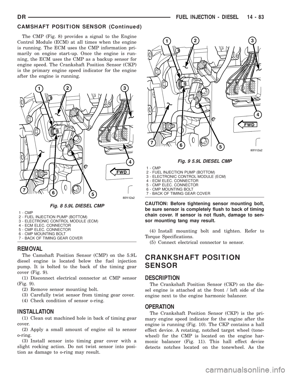
The CMP (Fig. 8) provides a signal to the Engine
Control Module (ECM) at all times when the engine
is running. The ECM uses the CMP information pri-
marily on engine start-up. Once the engine is run-
ning, the ECM uses the CMP as a backup sensor for
engine speed. The Crankshaft Position Sensor (CKP)
is the primary engine speed indicator for the engine
after the engine is running.
REMOVAL
The Camshaft Position Sensor (CMP) on the 5.9L
diesel engine is located below the fuel injection
pump. It is bolted to the back of the timing gear
cover (Fig. 9).
(1) Disconnect electrical connector at CMP sensor
(Fig. 9).
(2) Remove sensor mounting bolt.
(3) Carefully twist sensor from timing gear cover.
(4) Check condition of sensor o-ring.
INSTALLATION
(1) Clean out machined hole in back of timing gear
cover.
(2) Apply a small amount of engine oil to sensor
o-ring.
(3) Install sensor into timing gear cover with a
slight rocking action. Do not twist sensor into posi-
tion as damage to o-ring may result.CAUTION: Before tightening sensor mounting bolt,
be sure sensor is completely flush to back of timing
chain cover. If sensor is not flush, damage to sen-
sor mounting tang may result.
(4) Install mounting bolt and tighten. Refer to
Torque Specifications.
(5) Connect electrical connector to sensor.
CRANKSHAFT POSITION
SENSOR
DESCRIPTION
The Crankshaft Position Sensor (CKP) on the die-
sel engine is attached at the front / left side of the
engine next to the engine harmonic balancer.
OPERATION
The Crankshaft Position Sensor (CKP) is the pri-
mary engine speed indicator for the engine after the
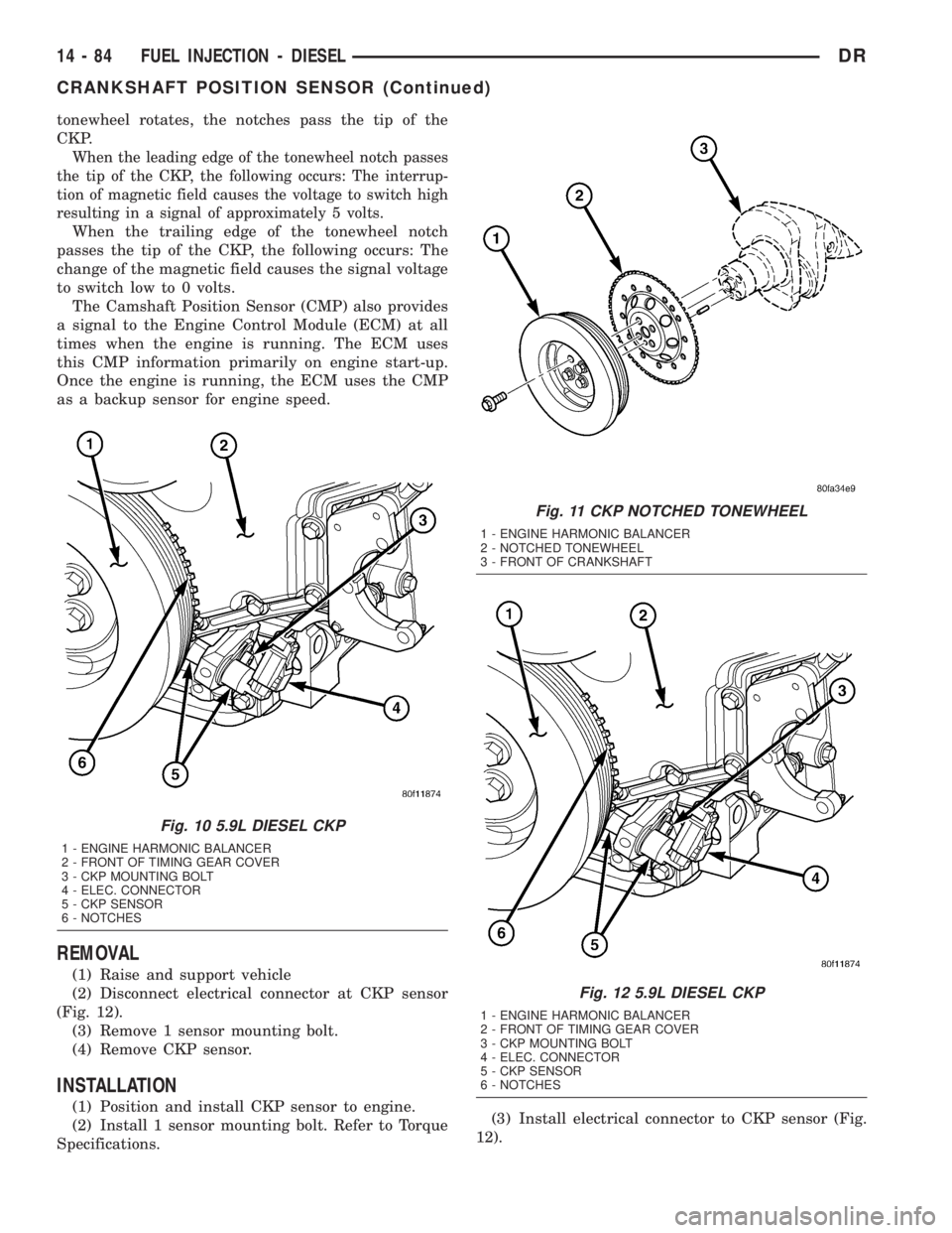
engine is running (Fig. 10). The CKP contains a hall
effect device. A rotating, notched target wheel (tone-
wheel) for the CMP is located on the engine har-
monic balancer (Fig. 11). This hall effect device
detects notches located on the tonewheel. As the
Fig. 8 5.9L DIESEL CMP
1 - CMP
2 - FUEL INJECTION PUMP (BOTTOM)
3 - ELECTRONIC CONTROL MODULE (ECM)
4 - ECM ELEC. CONNECTOR
5 - CMP ELEC. CONNECTOR
6 - CMP MOUNTING BOLT
7 - BACK OF TIMING GEAR COVER
Fig. 9 5.9L DIESEL CMP
1 - CMP
2 - FUEL INJECTION PUMP (BOTTOM)
3 - ELECTRONIC CONTROL MODULE (ECM)
4 - ECM ELEC. CONNECTOR
5 - CMP ELEC. CONNECTOR
6 - CMP MOUNTING BOLT
7 - BACK OF TIMING GEAR COVER
DRFUEL INJECTION - DIESEL 14 - 83
CAMSHAFT POSITION SENSOR (Continued)
Page 1781 of 2895
tonewheel rotates, the notches pass the tip of the
CKP.
When the leading edge of the tonewheel notch passes
the tip of the CKP, the following occurs: The interrup-
tion of magnetic field causes the voltage to switch high
resulting in a signal of approximately 5 volts.
When the trailing edge of the tonewheel notch
passes the tip of the CKP, the following occurs: The
change of the magnetic field causes the signal voltage
to switch low to 0 volts.
The Camshaft Position Sensor (CMP) also provides
a signal to the Engine Control Module (ECM) at all
times when the engine is running. The ECM uses
this CMP information primarily on engine start-up.
Once the engine is running, the ECM uses the CMP
as a backup sensor for engine speed.
REMOVAL
(1) Raise and support vehicle
(2) Disconnect electrical connector at CKP sensor
(Fig. 12).
(3) Remove 1 sensor mounting bolt.
(4) Remove CKP sensor.
INSTALLATION
(1) Position and install CKP sensor to engine.
(2) Install 1 sensor mounting bolt. Refer to Torque
Specifications.(3) Install electrical connector to CKP sensor (Fig.
12).
Fig. 10 5.9L DIESEL CKP
1 - ENGINE HARMONIC BALANCER
2 - FRONT OF TIMING GEAR COVER
3 - CKP MOUNTING BOLT
4 - ELEC. CONNECTOR
5 - CKP SENSOR
6 - NOTCHES
Fig. 11 CKP NOTCHED TONEWHEEL
1 - ENGINE HARMONIC BALANCER
2 - NOTCHED TONEWHEEL
3 - FRONT OF CRANKSHAFT
Fig. 12 5.9L DIESEL CKP
1 - ENGINE HARMONIC BALANCER
2 - FRONT OF TIMING GEAR COVER
3 - CKP MOUNTING BOLT
4 - ELEC. CONNECTOR
5 - CKP SENSOR
6 - NOTCHES
14 - 84 FUEL INJECTION - DIESELDR
CRANKSHAFT POSITION SENSOR (Continued)
Page 1782 of 2895
FUEL CONTROL ACTUATOR
DESCRIPTION
The Fuel Control Actuator (FCA) is located at the
rear of the high-pressure, fuel injection pump.
OPERATION
The Fuel Control Actuator (FCA) is an electroni-
cally controlled solenoid valve. The ECM controls the
amount of fuel that enters the high-pressure pumping
chambers by opening and closing the FCA based on a
demanded fuel pressure. When the FCA is opened,
the maximum amount of fuel is being supplied to the
fuel injection pump. Any fuel that does not enter the
injection pump is directed to the overflow valve. The
overflow valve regulates how much excess fuel is used
for lubrication of the pump and how much is returned
to the fuel tank through the drain manifold.
An audible click from the FCA is normal when
operating the key to either the ON or OFF positions.
REMOVAL
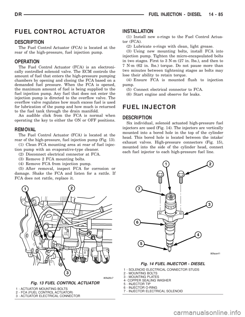
The Fuel Control Actuator (FCA) is located at the
rear of the high-pressure, fuel injection pump (Fig. 13).
(1) Clean FCA mounting area at rear of fuel injec-
tion pump with an evaporative-type cleaner.
(2) Disconnect electrical connector at FCA.
(3) Remove 2 FCA mounting bolts.
(4) Remove FCA from injection pump.
(5) After removal, inspect FCA for corrosion or
damage. Shake the FCA and listen for a rattle. If
FCA does not rattle, replace it.
INSTALLATION
(1) Install new o-rings to the Fuel Control Actua-
tor (FCA).
(2) Lubricate o-rings with clean, light grease.
(3) Using new mounting bolts, install FCA into
injection pump. Tighten the micro-encapsulated bolts
in two stages. First to 3 N´m (27 in. lbs.), and then to
7 N´m (62 in. lbs.) torque. Do not pause more than
two minutes between tightening stages as bolts may
lose their ability to retain torque.
(4) Ensure FCA is mounted flush to injection
pump.
(5) Connect electrical connector to FCA.
(6) Start engine and observe for leaks.
FUEL INJECTOR
DESCRIPTION
Six individual, solenoid actuated high-pressure fuel
injectors are used (Fig. 14). The injectors are vertically
mounted into a bored hole in the top of the cylinder
head. This bored hole is located between the intake/
exhaust valves. High-pressure connectors (Fig. 15),
mounted into the side of the cylinder head, connect
each fuel injector to each high-pressure fuel line.
Fig. 13 FUEL CONTROL ACTUATOR
1 - ACTUATOR MOUNTING BOLTS
2 - FCA (FUEL CONTROL ACTUATOR)
3 - ACTUATOR ELECTRICAL CONNECTOR
Fig. 14 FUEL INJECTOR - DIESEL
1 - SOLENOID ELECTRICAL CONNECTOR STUDS
2 - MOUNTING BOLTS
3 - MOUNTING PLATES
4- COPPER SEALING WASHER
5 - INJECTOR TIP
6 - INJECTOR O-RING
7 - INJECTOR ELECTRICAL SOLENOID
DRFUEL INJECTION - DIESEL 14 - 85