2003 DODGE RAM electrical
[x] Cancel search: electricalPage 1733 of 2895
(2) Install and tighten two mounting bolts (screws)
to 7 N´m (60 in. lbs.) torque.
(3) Install electrical connector.
(4) Install air resonator to throttle body.
5.7L V-8
The IAC motor is not serviceable on the 5.7L V-8
engine.
5.9L V-8
The IAC motor is located on the back of the throt-
tle body (Fig. 22).
(1) Install IAC motor to throttle body.
(2) Install and tighten two mounting bolts (screws)
to 7 N´m (60 in. lbs.) torque.
(3) Install electrical connector.
(4) Install air resonator to throttle body.
8.0L V-10
The IAC motor is located on the back of the throt-
tle body (Fig. 23).
(1) Install IAC motor to throttle body.
(2) Install and tighten two mounting bolts (screws)
to 7 N´m (60 in. lbs.) torque.
(3) Install electrical connector.
(4) Install air cleaner housing to throttle body.
(5) Install 4 air cleaner housing mounting nuts.
Tighten nuts to 11 N´m (96 in. lbs.) torque.
(6) Install air cleaner housing cover.
INTAKE AIR TEMPERATURE
SENSOR
DESCRIPTION
The 2±wire Intake Manifold Air Temperature (IAT)
sensor is installed in the intake manifold with the
sensor element extending into the air stream.
The IAT sensor is a two-wire Negative Thermal
Coefficient (NTC) sensor. Meaning, as intake mani-
fold temperature increases, resistance (voltage) in the
sensor decreases. As temperature decreases, resis-
tance (voltage) in the sensor increases.
OPERATION
The IAT sensor provides an input voltage to the
Powertrain Control Module (PCM) indicating the
density of the air entering the intake manifold based
upon intake manifold temperature. At key-on, a
5±volt power circuit is supplied to the sensor from
the PCM. The sensor is grounded at the PCM
through a low-noise, sensor-return circuit.
The PCM uses this input to calculate the following:
²Injector pulse-width²Adjustment of spark timing (to help prevent
spark knock with high intake manifold air-charge
temperatures)
The resistance values of the IAT sensor is the same
as for the Engine Coolant Temperature (ECT) sensor.
REMOVAL
3.7L V-6
The intake manifold air temperature (IAT) sensor
is installed into the left side of intake manifold ple-
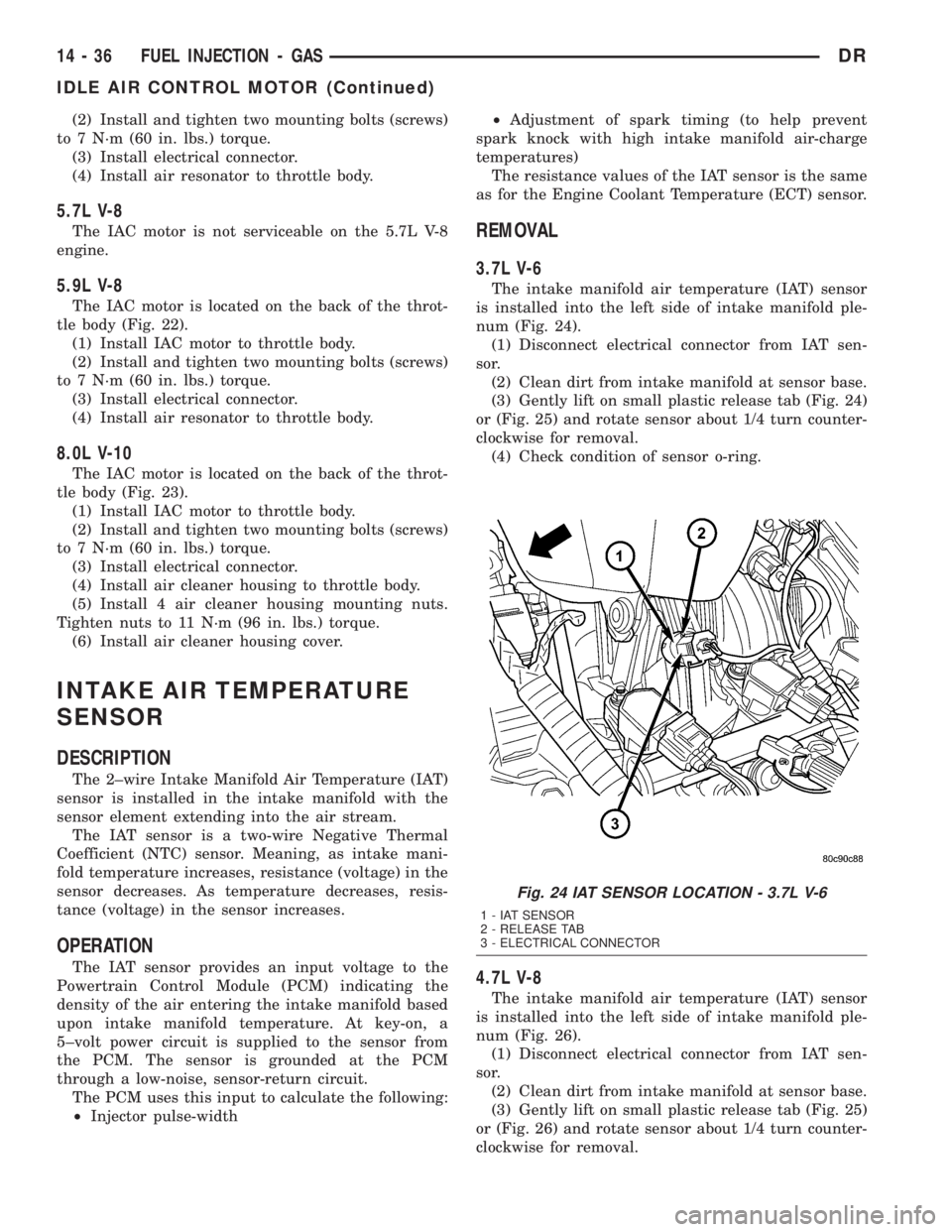
num (Fig. 24).
(1) Disconnect electrical connector from IAT sen-
sor.
(2) Clean dirt from intake manifold at sensor base.
(3) Gently lift on small plastic release tab (Fig. 24)
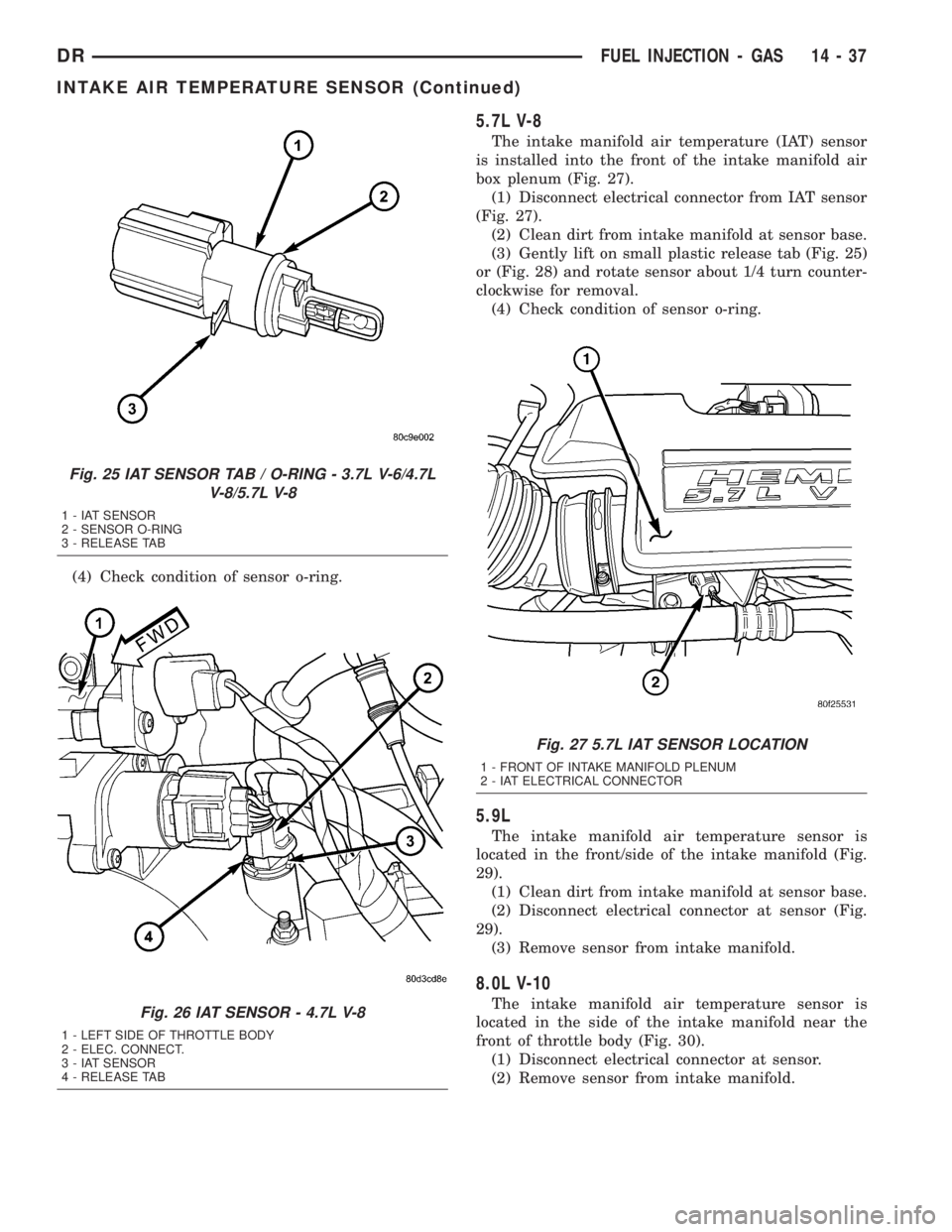
or (Fig. 25) and rotate sensor about 1/4 turn counter-
clockwise for removal.
(4) Check condition of sensor o-ring.
4.7L V-8
The intake manifold air temperature (IAT) sensor
is installed into the left side of intake manifold ple-
num (Fig. 26).
(1) Disconnect electrical connector from IAT sen-
sor.
(2) Clean dirt from intake manifold at sensor base.
(3) Gently lift on small plastic release tab (Fig. 25)
or (Fig. 26) and rotate sensor about 1/4 turn counter-
clockwise for removal.
Fig. 24 IAT SENSOR LOCATION - 3.7L V-6
1 - IAT SENSOR
2 - RELEASE TAB
3 - ELECTRICAL CONNECTOR
14 - 36 FUEL INJECTION - GASDR
IDLE AIR CONTROL MOTOR (Continued)
Page 1734 of 2895
(4) Check condition of sensor o-ring.
5.7L V-8
The intake manifold air temperature (IAT) sensor
is installed into the front of the intake manifold air
box plenum (Fig. 27).
(1) Disconnect electrical connector from IAT sensor
(Fig. 27).
(2) Clean dirt from intake manifold at sensor base.
(3) Gently lift on small plastic release tab (Fig. 25)
or (Fig. 28) and rotate sensor about 1/4 turn counter-
clockwise for removal.
(4) Check condition of sensor o-ring.
5.9L
The intake manifold air temperature sensor is
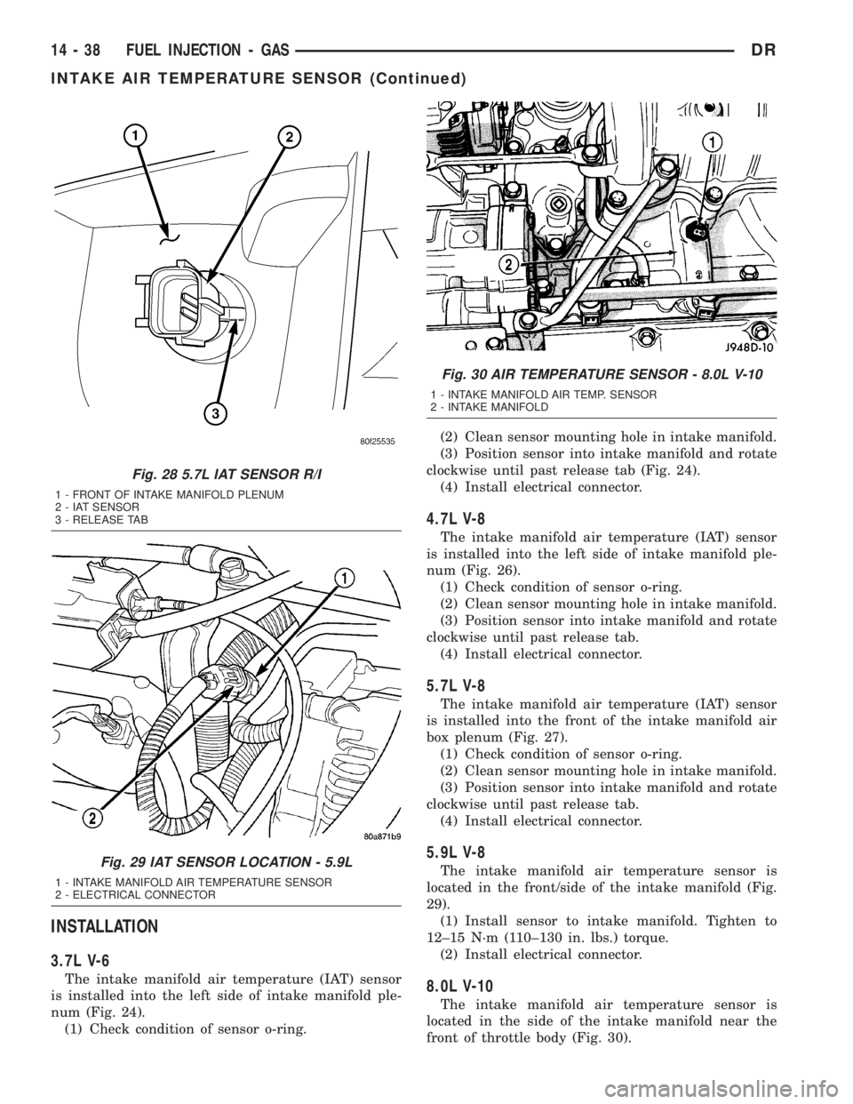
located in the front/side of the intake manifold (Fig.
29).
(1) Clean dirt from intake manifold at sensor base.
(2) Disconnect electrical connector at sensor (Fig.
29).
(3) Remove sensor from intake manifold.
8.0L V-10
The intake manifold air temperature sensor is
located in the side of the intake manifold near the
front of throttle body (Fig. 30).
(1) Disconnect electrical connector at sensor.
(2) Remove sensor from intake manifold.
Fig. 25 IAT SENSOR TAB / O-RING - 3.7L V-6/4.7L
V-8/5.7L V-8
1 - IAT SENSOR
2 - SENSOR O-RING
3 - RELEASE TAB
Fig. 26 IAT SENSOR - 4.7L V-8
1 - LEFT SIDE OF THROTTLE BODY
2 - ELEC. CONNECT.
3 - IAT SENSOR
4 - RELEASE TAB
Fig. 27 5.7L IAT SENSOR LOCATION
1 - FRONT OF INTAKE MANIFOLD PLENUM
2 - IAT ELECTRICAL CONNECTOR
DRFUEL INJECTION - GAS 14 - 37
INTAKE AIR TEMPERATURE SENSOR (Continued)
Page 1735 of 2895
INSTALLATION
3.7L V-6
The intake manifold air temperature (IAT) sensor
is installed into the left side of intake manifold ple-
num (Fig. 24).
(1) Check condition of sensor o-ring.(2) Clean sensor mounting hole in intake manifold.
(3) Position sensor into intake manifold and rotate
clockwise until past release tab (Fig. 24).
(4) Install electrical connector.
4.7L V-8
The intake manifold air temperature (IAT) sensor
is installed into the left side of intake manifold ple-
num (Fig. 26).
(1) Check condition of sensor o-ring.
(2) Clean sensor mounting hole in intake manifold.
(3) Position sensor into intake manifold and rotate
clockwise until past release tab.
(4) Install electrical connector.
5.7L V-8
The intake manifold air temperature (IAT) sensor
is installed into the front of the intake manifold air
box plenum (Fig. 27).
(1) Check condition of sensor o-ring.
(2) Clean sensor mounting hole in intake manifold.
(3) Position sensor into intake manifold and rotate
clockwise until past release tab.
(4) Install electrical connector.
5.9L V-8
The intake manifold air temperature sensor is
located in the front/side of the intake manifold (Fig.
29).
(1) Install sensor to intake manifold. Tighten to
12±15 N´m (110±130 in. lbs.) torque.
(2) Install electrical connector.
8.0L V-10
The intake manifold air temperature sensor is
located in the side of the intake manifold near the
front of throttle body (Fig. 30).
Fig. 28 5.7L IAT SENSOR R/I
1 - FRONT OF INTAKE MANIFOLD PLENUM
2 - IAT SENSOR
3 - RELEASE TAB
Fig. 29 IAT SENSOR LOCATION - 5.9L
1 - INTAKE MANIFOLD AIR TEMPERATURE SENSOR
2 - ELECTRICAL CONNECTOR
Fig. 30 AIR TEMPERATURE SENSOR - 8.0L V-10
1 - INTAKE MANIFOLD AIR TEMP. SENSOR
2 - INTAKE MANIFOLD
14 - 38 FUEL INJECTION - GASDR
INTAKE AIR TEMPERATURE SENSOR (Continued)
Page 1736 of 2895
(1) Install sensor to intake manifold. Tighten to
12±15 N´m (110±130 in. lbs.) torque.
(2) Install electrical connector.
MAP SENSOR
DESCRIPTION
3.7L V-6
The Manifold Absolute Pressure (MAP) sensor is
mounted into the front of the intake manifold with 2
screws.
4.7L V-8
The Manifold Absolute Pressure (MAP) sensor is
mounted into the front of the intake manifold with 2
screws.
5.7L V-8
The Manifold Absolute Pressure (MAP) sensor is
mounted to the front of the intake manifold air ple-
num box.
5.9L V-8
The Manifold Absolute Pressure (MAP) sensor is
mounted to the front of the throttle body with 2
screws.
8.0L V-10
The Manifold Absolute Pressure (MAP) sensor is
mounted into the right side of the intake manifold.
OPERATION
The MAP sensor is used as an input to the Power-
train Control Module (PCM). It contains a silicon
based sensing unit to provide data on the manifold
vacuum that draws the air/fuel mixture into the com-
bustion chamber. The PCM requires this information
to determine injector pulse width and spark advance.
When manifold absolute pressure (MAP) equals
Barometric pressure, the pulse width will be at max-
imum.
A 5 volt reference is supplied from the PCM and
returns a voltage signal to the PCM that reflects
manifold pressure. The zero pressure reading is 0.5V
and full scale is 4.5V. For a pressure swing of 0±15
psi, the voltage changes 4.0V. To operate the sensor,
it is supplied a regulated 4.8 to 5.1 volts. Ground is
provided through the low-noise, sensor return circuit
at the PCM.
The MAP sensor input is the number one contrib-
utor to fuel injector pulse width. The most important
function of the MAP sensor is to determine baromet-
ric pressure. The PCM needs to know if the vehicle is
at sea level or at a higher altitude, because the airdensity changes with altitude. It will also help to cor-
rect for varying barometric pressure. Barometric
pressure and altitude have a direct inverse correla-
tion; as altitude goes up, barometric goes down. At
key-on, the PCM powers up and looks at MAP volt-
age, and based upon the voltage it sees, it knows the
current barometric pressure (relative to altitude).
Once the engine starts, the PCM looks at the voltage
again, continuously every 12 milliseconds, and com-
pares the current voltage to what it was at key-on.
The difference between current voltage and what it
was at key-on, is manifold vacuum.
During key-on (engine not running) the sensor
reads (updates) barometric pressure. A normal range
can be obtained by monitoring a known good sensor.
As the altitude increases, the air becomes thinner
(less oxygen). If a vehicle is started and driven to a
very different altitude than where it was at key-on,
the barometric pressure needs to be updated. Any
time the PCM sees Wide Open Throttle (WOT), based
upon Throttle Position Sensor (TPS) angle and RPM,
it will update barometric pressure in the MAP mem-
ory cell. With periodic updates, the PCM can make
its calculations more effectively.
The PCM uses the MAP sensor input to aid in cal-
culating the following:
²Manifold pressure
²Barometric pressure
²Engine load
²Injector pulse-width
²Spark-advance programs
²Shift-point strategies (certain automatic trans-
missions only)
²Idle speed
²Decel fuel shutoff
The MAP sensor signal is provided from a single
piezoresistive element located in the center of a dia-
phragm. The element and diaphragm are both made
of silicone. As manifold pressure changes, the dia-
phragm moves causing the element to deflect, which
stresses the silicone. When silicone is exposed to
stress, its resistance changes. As manifold vacuum
increases, the MAP sensor input voltage decreases
proportionally. The sensor also contains electronics
that condition the signal and provide temperature
compensation.
The PCM recognizes a decrease in manifold pres-
sure by monitoring a decrease in voltage from the
reading stored in the barometric pressure memory
cell. The MAP sensor is a linear sensor; meaning as
pressure changes, voltage changes proportionately.
The range of voltage output from the sensor is usu-
ally between 4.6 volts at sea level to as low as 0.3
volts at 26 in. of Hg. Barometric pressure is the pres-
sure exerted by the atmosphere upon an object. At
sea level on a standard day, no storm, barometric
DRFUEL INJECTION - GAS 14 - 39
INTAKE AIR TEMPERATURE SENSOR (Continued)
Page 1737 of 2895
pressure is approximately 29.92 in Hg. For every 100
feet of altitude, barometric pressure drops 0.10 in.
Hg. If a storm goes through, it can change baromet-
ric pressure from what should be present for that
altitude. You should know what the average pressure
and corresponding barometric pressure is for your
area.
REMOVAL
3.7L V-6
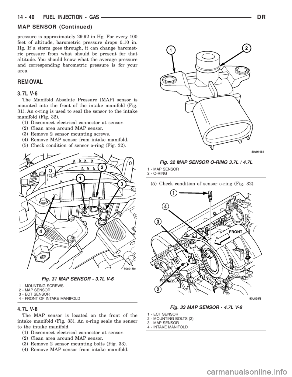
The Manifold Absolute Pressure (MAP) sensor is
mounted into the front of the intake manifold (Fig.
31). An o-ring is used to seal the sensor to the intake
manifold (Fig. 32).
(1) Disconnect electrical connector at sensor.
(2) Clean area around MAP sensor.
(3) Remove 2 sensor mounting screws.
(4) Remove MAP sensor from intake manifold.
(5) Check condition of sensor o-ring (Fig. 32).
4.7L V-8
The MAP sensor is located on the front of the
intake manifold (Fig. 33). An o-ring seals the sensor
to the intake manifold.
(1) Disconnect electrical connector at sensor.
(2) Clean area around MAP sensor.
(3) Remove 2 sensor mounting bolts (Fig. 33).
(4) Remove MAP sensor from intake manifold.(5) Check condition of sensor o-ring (Fig. 32).
Fig. 31 MAP SENSOR - 3.7L V-6
1 - MOUNTING SCREWS
2 - MAP SENSOR
3 - ECT SENSOR
4 - FRONT OF INTAKE MANIFOLD
Fig. 32 MAP SENSOR O-RING 3.7L / 4.7L
1 - MAP SENSOR
2 - O-RING
Fig. 33 MAP SENSOR - 4.7L V-8
1 - ECT SENSOR
2 - MOUNTING BOLTS (2)
3 - MAP SENSOR
4 - INTAKE MANIFOLD
14 - 40 FUEL INJECTION - GASDR
MAP SENSOR (Continued)
Page 1738 of 2895
5.7L V-8
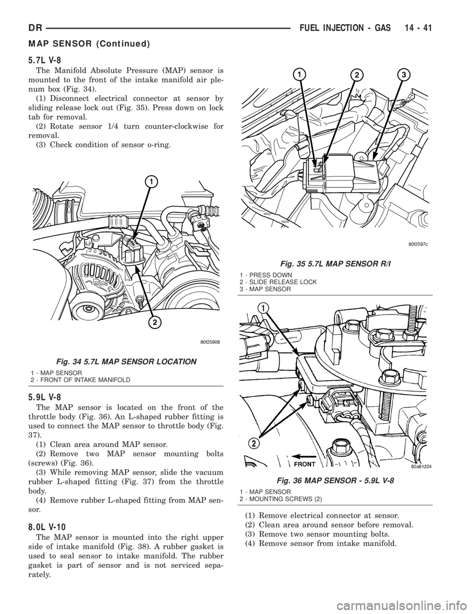
The Manifold Absolute Pressure (MAP) sensor is
mounted to the front of the intake manifold air ple-
num box (Fig. 34).
(1) Disconnect electrical connector at sensor by
sliding release lock out (Fig. 35). Press down on lock
tab for removal.
(2) Rotate sensor 1/4 turn counter-clockwise for
removal.
(3) Check condition of sensor o-ring.
5.9L V-8
The MAP sensor is located on the front of the
throttle body (Fig. 36). An L-shaped rubber fitting is
used to connect the MAP sensor to throttle body (Fig.
37).
(1) Clean area around MAP sensor.
(2) Remove two MAP sensor mounting bolts
(screws) (Fig. 36).
(3) While removing MAP sensor, slide the vacuum
rubber L-shaped fitting (Fig. 37) from the throttle
body.
(4) Remove rubber L-shaped fitting from MAP sen-
sor.
8.0L V-10
The MAP sensor is mounted into the right upper
side of intake manifold (Fig. 38). A rubber gasket is
used to seal sensor to intake manifold. The rubber
gasket is part of sensor and is not serviced sepa-
rately.(1) Remove electrical connector at sensor.
(2) Clean area around sensor before removal.
(3) Remove two sensor mounting bolts.
(4) Remove sensor from intake manifold.
Fig. 34 5.7L MAP SENSOR LOCATION
1 - MAP SENSOR
2 - FRONT OF INTAKE MANIFOLD
Fig. 35 5.7L MAP SENSOR R/I
1 - PRESS DOWN
2 - SLIDE RELEASE LOCK
3 - MAP SENSOR
Fig. 36 MAP SENSOR - 5.9L V-8
1 - MAP SENSOR
2 - MOUNTING SCREWS (2)
DRFUEL INJECTION - GAS 14 - 41
MAP SENSOR (Continued)
Page 1739 of 2895
INSTALLATION
3.7L V-6
The Manifold Absolute Pressure (MAP) sensor is
mounted into the front of the intake manifold (Fig.
31). An o-ring is used to seal the sensor to the intake
manifold (Fig. 32).
(1) Clean MAP sensor mounting hole at intake
manifold.
(2) Check MAP sensor o-ring seal for cuts or tears.
(3) Position sensor into manifold.(4) Install MAP sensor mounting bolts (screws).
Refer to Torque Specifications.
(5) Connect electrical connector.
4.7L V-8
The MAP sensor is located on the front of the
intake manifold (Fig. 33). An o-ring seals the sensor
to the intake manifold (Fig. 32).
(1) Clean MAP sensor mounting hole at intake
manifold.
(2) Check MAP sensor o-ring seal for cuts or tears.
(3) Position sensor into manifold.
(4) Install MAP sensor mounting bolts (screws).
Refer to Torque Specifications.
(5) Connect electrical connector.
5.7L V-8
The Manifold Absolute Pressure (MAP) sensor is
mounted to the front of the intake manifold air ple-
num box (Fig. 34).
(1) Clean MAP sensor mounting hole at intake
manifold.
(2) Check MAP sensor o-ring seal for cuts or tears.
(3) Position sensor into manifold.
(4) Rotate sensor 1/4 turn clockwise for installa-
tion.
(5) Connect electrical connector.
5.9L V-8
The MAP sensor is located on the front of the
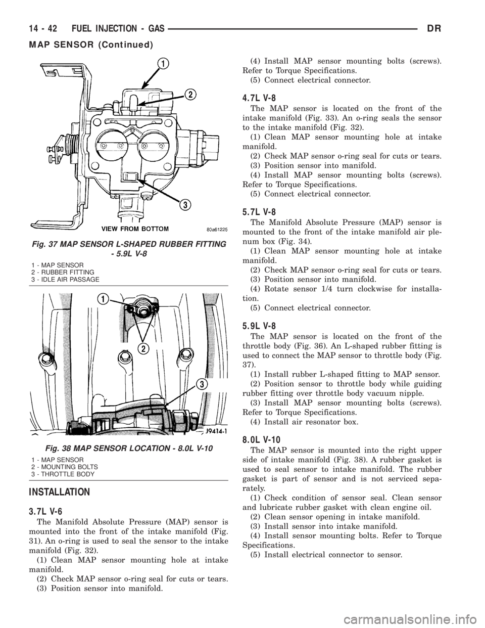
throttle body (Fig. 36). An L-shaped rubber fitting is
used to connect the MAP sensor to throttle body (Fig.
37).
(1) Install rubber L-shaped fitting to MAP sensor.
(2) Position sensor to throttle body while guiding
rubber fitting over throttle body vacuum nipple.
(3) Install MAP sensor mounting bolts (screws).
Refer to Torque Specifications.
(4) Install air resonator box.
8.0L V-10
The MAP sensor is mounted into the right upper
side of intake manifold (Fig. 38). A rubber gasket is
used to seal sensor to intake manifold. The rubber
gasket is part of sensor and is not serviced sepa-
rately.
(1) Check condition of sensor seal. Clean sensor
and lubricate rubber gasket with clean engine oil.
(2) Clean sensor opening in intake manifold.
(3) Install sensor into intake manifold.
(4) Install sensor mounting bolts. Refer to Torque
Specifications.
(5) Install electrical connector to sensor.
Fig. 37 MAP SENSOR L-SHAPED RUBBER FITTING
- 5.9L V-8
1 - MAP SENSOR
2 - RUBBER FITTING
3 - IDLE AIR PASSAGE
Fig. 38 MAP SENSOR LOCATION - 8.0L V-10
1 - MAP SENSOR
2 - MOUNTING BOLTS
3 - THROTTLE BODY
14 - 42 FUEL INJECTION - GASDR
MAP SENSOR (Continued)
Page 1741 of 2895
Downstream Sensor - Federal Emissions
Package :The downstream oxygen sensor (1/2) is
also used to determine the correct air-fuel ratio. As
the oxygen content changes at the downstream sen-
sor, the PCM calculates how much air-fuel ratio
change is required. The PCM then looks at the
upstream oxygen sensor voltage and changes fuel
delivery until the upstream sensor voltage changes
enough to correct the downstream sensor voltage
(oxygen content).
The downstream oxygen sensor also provides an
input to determine catalytic convertor efficiency.
Upstream Sensors - California Emissions
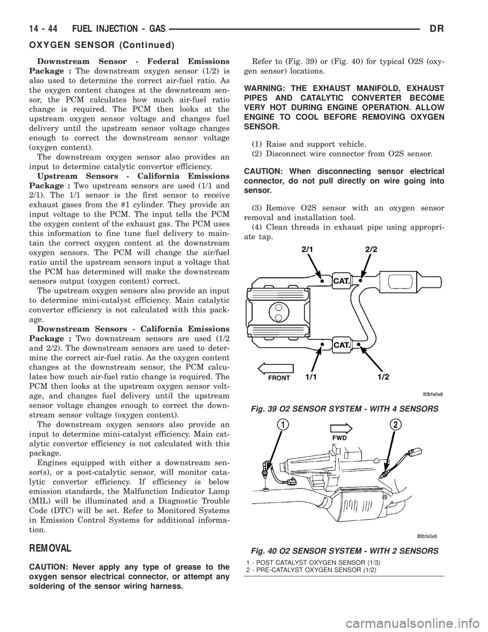
Package :Two upstream sensors are used (1/1 and
2/1). The 1/1 sensor is the first sensor to receive
exhaust gases from the #1 cylinder. They provide an
input voltage to the PCM. The input tells the PCM
the oxygen content of the exhaust gas. The PCM uses
this information to fine tune fuel delivery to main-
tain the correct oxygen content at the downstream
oxygen sensors. The PCM will change the air/fuel
ratio until the upstream sensors input a voltage that
the PCM has determined will make the downstream
sensors output (oxygen content) correct.
The upstream oxygen sensors also provide an input
to determine mini-catalyst efficiency. Main catalytic
convertor efficiency is not calculated with this pack-
age.
Downstream Sensors - California Emissions
Package :Two downstream sensors are used (1/2
and 2/2). The downstream sensors are used to deter-
mine the correct air-fuel ratio. As the oxygen content
changes at the downstream sensor, the PCM calcu-
lates how much air-fuel ratio change is required. The
PCM then looks at the upstream oxygen sensor volt-
age, and changes fuel delivery until the upstream
sensor voltage changes enough to correct the down-
stream sensor voltage (oxygen content).
The downstream oxygen sensors also provide an
input to determine mini-catalyst efficiency. Main cat-
alytic convertor efficiency is not calculated with this
package.
Engines equipped with either a downstream sen-
sor(s), or a post-catalytic sensor, will monitor cata-
lytic convertor efficiency. If efficiency is below
emission standards, the Malfunction Indicator Lamp
(MIL) will be illuminated and a Diagnostic Trouble
Code (DTC) will be set. Refer to Monitored Systems
in Emission Control Systems for additional informa-
tion.
REMOVAL
CAUTION: Never apply any type of grease to the
oxygen sensor electrical connector, or attempt any
soldering of the sensor wiring harness.Refer to (Fig. 39) or (Fig. 40) for typical O2S (oxy-
gen sensor) locations.
WARNING: THE EXHAUST MANIFOLD, EXHAUST
PIPES AND CATALYTIC CONVERTER BECOME
VERY HOT DURING ENGINE OPERATION. ALLOW
ENGINE TO COOL BEFORE REMOVING OXYGEN
SENSOR.
(1) Raise and support vehicle.
(2) Disconnect wire connector from O2S sensor.
CAUTION: When disconnecting sensor electrical
connector, do not pull directly on wire going into
sensor.
(3) Remove O2S sensor with an oxygen sensor
removal and installation tool.
(4) Clean threads in exhaust pipe using appropri-
ate tap.
Fig. 39 O2 SENSOR SYSTEM - WITH 4 SENSORS
Fig. 40 O2 SENSOR SYSTEM - WITH 2 SENSORS
1 - POST CATALYST OXYGEN SENSOR (1/3)
2 - PRE-CATALYST OXYGEN SENSOR (1/2)
14 - 44 FUEL INJECTION - GASDR
OXYGEN SENSOR (Continued)