2003 DODGE RAM electrical
[x] Cancel search: electricalPage 1803 of 2895
REMOVAL
SERVICE PRECAUTIONS
NOTE: The steering column on vehicles equipped
with an automatic transmission is not equipped
with an internal locking shaft with the ignition cyl-
inder. Alternative methods of locking the steering
wheel for service will have to be used.
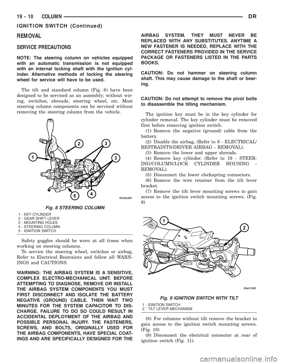
The tilt and standard column (Fig. 8) have been
designed to be serviced as an assembly; without wir-
ing, switches, shrouds, steering wheel, etc. Most
steering column components can be serviced without
removing the steering column from the vehicle.
Safety goggles should be worn at all times when
working on steering columns.
To service the steering wheel, switches or airbag,
Refer to Electrical Restraints and follow all WARN-
INGS and CAUTIONS.
WARNING: THE AIRBAG SYSTEM IS A SENSITIVE,
COMPLEX ELECTRO-MECHANICAL UNIT. BEFORE
ATTEMPTING TO DIAGNOSE, REMOVE OR INSTALL
THE AIRBAG SYSTEM COMPONENTS YOU MUST
FIRST DISCONNECT AND ISOLATE THE BATTERY
NEGATIVE (GROUND) CABLE. THEN WAIT TWO
MINUTES FOR THE SYSTEM CAPACITOR TO DIS-
CHARGE. FAILURE TO DO SO COULD RESULT IN
ACCIDENTAL DEPLOYMENT OF THE AIRBAG AND
POSSIBLE PERSONAL INJURY. THE FASTENERS,
SCREWS, AND BOLTS, ORIGINALLY USED FOR
THE AIRBAG COMPONENTS, HAVE SPECIAL COAT-
INGS AND ARE SPECIFICALLY DESIGNED FOR THEAIRBAG SYSTEM. THEY MUST NEVER BE
REPLACED WITH ANY SUBSTITUTES. ANYTIME A
NEW FASTENER IS NEEDED, REPLACE WITH THE
CORRECT FASTENERS PROVIDED IN THE SERVICE
PACKAGE OR FASTENERS LISTED IN THE PARTS
BOOKS.
CAUTION: Do not hammer on steering column
shaft. This may cause damage to the shaft or bear-
ing.
CAUTION: Do not attempt to remove the pivot bolts
to disassemble the tilting mechanism.
The ignition key must be in the key cylinder for
cylinder removal. The key cylinder must be removed
first before removing ignition switch.
(1) Remove the negative (ground) cable from the
battery.
(2) Disable the airbag, (Refer to 8 - ELECTRICAL/
RESTRAINTS/DRIVER AIRBAG - REMOVAL).
(3) Remove the lower and upper shrouds.
(4) Remove key cylinder. (Refer to 19 - STEER-
ING/COLUMN/LOCK CYLINDER HOUSING -
REMOVAL).
(5) Disconnect the lower clockspring connectors.
(6) Remove the wire retainer from the tilt lever
bracket.
(7) Remove the tilt lever mounting screws to gain
access to the ignition switch mounting screws. (Fig.
9)
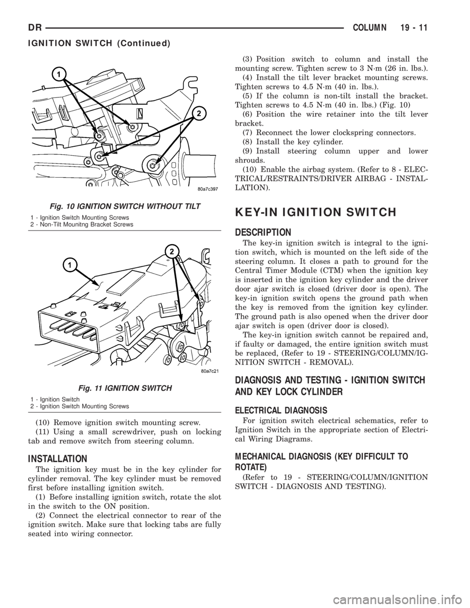
(8) For columns without tilt remove the bracket to
gain access to the ignition switch mounting screws.
(Fig. 10)
(9) Disconnect the electrical connector at rear of
ignition switch (Fig. 11).
Fig. 8 STEERING COLUMN
1 - KEY CYLINDER
2 - GEAR SHIFT LEVER
3 - MOUNTING HOLES
4 - STEERING COLUMN
5 - IGNITION SWITCH
Fig. 9 IGNITION SWITCH WITH TILT
1 - IGNITION SWITCH
2 - TILT LEVER MECHANISM
19 - 10 COLUMNDR
IGNITION SWITCH (Continued)
Page 1804 of 2895
(10) Remove ignition switch mounting screw.
(11) Using a small screwdriver, push on locking
tab and remove switch from steering column.
INSTALLATION
The ignition key must be in the key cylinder for
cylinder removal. The key cylinder must be removed
first before installing ignition switch.
(1) Before installing ignition switch, rotate the slot
in the switch to the ON position.
(2) Connect the electrical connector to rear of the
ignition switch. Make sure that locking tabs are fully
seated into wiring connector.(3) Position switch to column and install the
mounting screw. Tighten screw to 3 N´m (26 in. lbs.).
(4) Install the tilt lever bracket mounting screws.
Tighten screws to 4.5 N´m (40 in. lbs.).
(5) If the column is non-tilt install the bracket.
Tighten screws to 4.5 N´m (40 in. lbs.) (Fig. 10)
(6) Position the wire retainer into the tilt lever
bracket.
(7) Reconnect the lower clockspring connectors.
(8) Install the key cylinder.
(9) Install steering column upper and lower
shrouds.
(10) Enable the airbag system. (Refer to 8 - ELEC-
TRICAL/RESTRAINTS/DRIVER AIRBAG - INSTAL-
LATION).
KEY-IN IGNITION SWITCH
DESCRIPTION
The key-in ignition switch is integral to the igni-
tion switch, which is mounted on the left side of the
steering column. It closes a path to ground for the
Central Timer Module (CTM) when the ignition key
is inserted in the ignition key cylinder and the driver
door ajar switch is closed (driver door is open). The
key-in ignition switch opens the ground path when
the key is removed from the ignition key cylinder.
The ground path is also opened when the driver door
ajar switch is open (driver door is closed).
The key-in ignition switch cannot be repaired and,
if faulty or damaged, the entire ignition switch must
be replaced, (Refer to 19 - STEERING/COLUMN/IG-
NITION SWITCH - REMOVAL).
DIAGNOSIS AND TESTING - IGNITION SWITCH
AND KEY LOCK CYLINDER
ELECTRICAL DIAGNOSIS
For ignition switch electrical schematics, refer to
Ignition Switch in the appropriate section of Electri-
cal Wiring Diagrams.
MECHANICAL DIAGNOSIS (KEY DIFFICULT TO
ROTATE)
(Refer to 19 - STEERING/COLUMN/IGNITION
SWITCH - DIAGNOSIS AND TESTING).
Fig. 10 IGNITION SWITCH WITHOUT TILT
1 - Ignition Switch Mounting Screws
2 - Non-Tilt Mounitng Bracket Screws
Fig. 11 IGNITION SWITCH
1 - Ignition Switch
2 - Ignition Switch Mounting Screws
DRCOLUMN 19 - 11
IGNITION SWITCH (Continued)
Page 1806 of 2895
(2) Cycle the key from ACC to RUN and ensure
that the blocker does not stick or bind.
(3) Turn the key to the OFF position and ensure
that the shifter will not pull from the PARK position.
(4) Connect the over drive switch harness (if
equipped).
NOTE: Route and tie off harness to original loca-
tion.
(5) Connect the shift cable to the lever.
(6) Ensure the gear shift lever and transmission
are in the PARK position and snap the cable adjust
clip in place.
(7) Install a new brake light switch (Refer to 8 -
ELECTRICAL/LAMPS/LIGHTING - EXTERIOR/
BRAKE LAMP SWITCH - INSTALLATION).
(8) Install the SKIM and halo.
(9) Install the upper and lower column shroud.
(10) Install the column back into place and
tighten.
(11) Install the kneeblocker. (Refer to 23 - BODY/
INSTRUMENT PANEL/KNEE BLOCKER - INSTAL-
LATION).
UPPER STEERING COUPLING
REMOVAL
(1) Disconnect the negative battery cable.
NOTE: The steering column on vehicles with an
automatic transmission may not be equipped with
an internal locking shaft that allows the ignition key
cylinder to be locked with the key. Alternative meth-
ods of locking the steering wheel for service will
have to be used.(2) Lock the steering wheel with the tire in the
straight position.
(3) Remove and discard the lower pinch bolt.
(4) Lower the steering coupler shaft from the col-
umn.
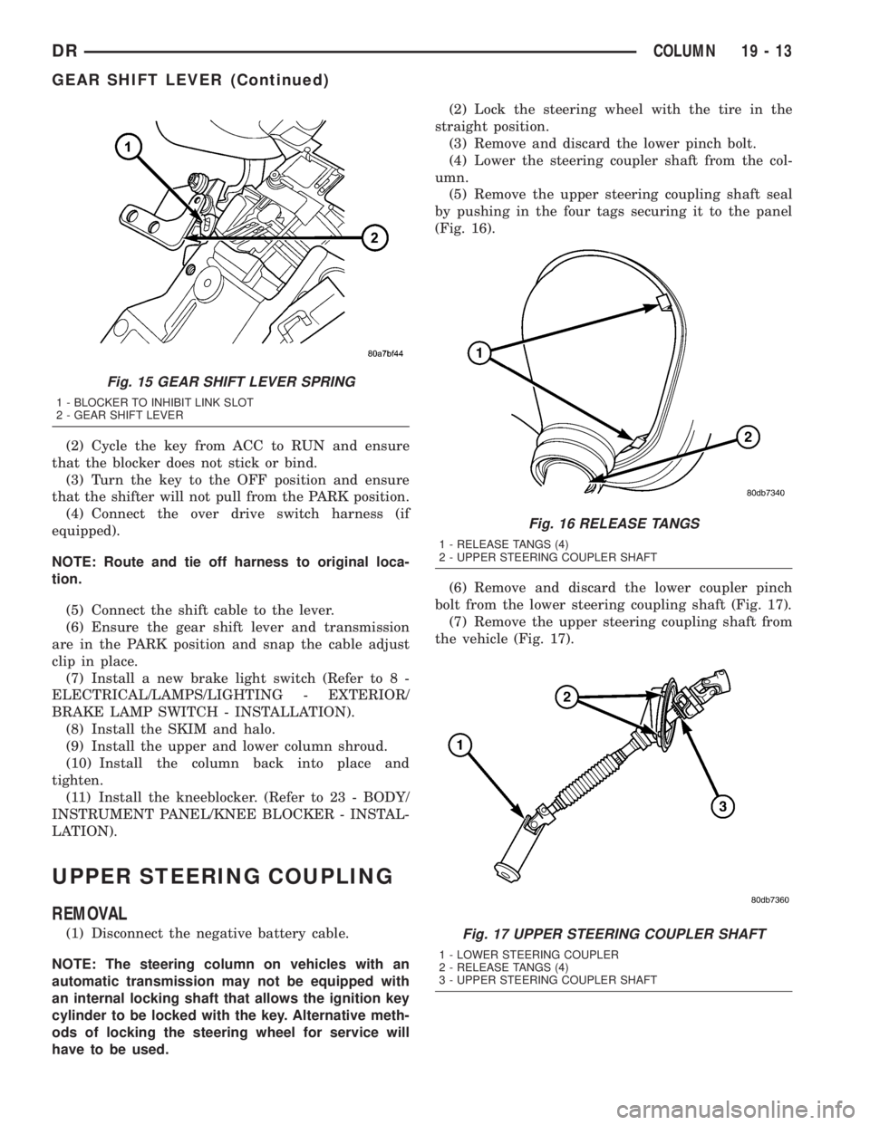
(5) Remove the upper steering coupling shaft seal
by pushing in the four tags securing it to the panel
(Fig. 16).
(6) Remove and discard the lower coupler pinch
bolt from the lower steering coupling shaft (Fig. 17).
(7) Remove the upper steering coupling shaft from
the vehicle (Fig. 17).
Fig. 15 GEAR SHIFT LEVER SPRING
1 - BLOCKER TO INHIBIT LINK SLOT
2 - GEAR SHIFT LEVER
Fig. 16 RELEASE TANGS
1 - RELEASE TANGS (4)
2 - UPPER STEERING COUPLER SHAFT
Fig. 17 UPPER STEERING COUPLER SHAFT
1 - LOWER STEERING COUPLER
2 - RELEASE TANGS (4)
3 - UPPER STEERING COUPLER SHAFT
DRCOLUMN 19 - 13
GEAR SHIFT LEVER (Continued)
Page 1808 of 2895
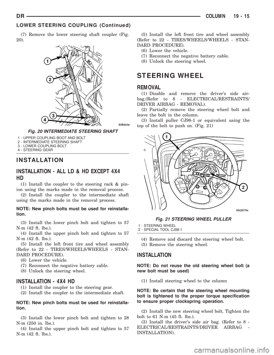
(7) Remove the lower steering shaft coupler (Fig.
20).
INSTALLATION
INSTALLATION - ALL LD & HD EXCEPT 4X4
HD
(1) Install the coupler to the steering rack & pin-
ion using the marks made in the removal process.
(2) Install the coupler to the intermediate shaft
using the marks made in the removal process.
NOTE: New pinch bolts must be used for reinstalla-
tion.
(3) Install the lower pinch bolt and tighten to 57
N´m (42 ft. lbs.).
(4) Install the upper pinch bolt and tighten to 57
N´m (42 ft. lbs.).
(5) Install the left front tire and wheel assembly
(Refer to 22 - TIRES/WHEELS/WHEELS - STAN-
DARD PROCEDURE).
(6) Lower the vehicle.
(7) Reconnect the negative battery cable.
(8) Unlock the steering wheel.
INSTALLATION - 4X4 HD
(1) Install the coupler to the steering gear.
(2) Install the coupler to the intermediate shaft.
NOTE: New pinch bolts must be used for reinstalla-
tion.
(3) Install the lower pinch bolt and tighten to 28
N´m (250 in. lbs.).
(4) Install the upper pinch bolt and tighten to 57
N´m (42 ft. lbs.).(5) Install the left front tire and wheel assembly
(Refer to 22 - TIRES/WHEELS/WHEELS - STAN-
DARD PROCEDURE).
(6) Lower the vehicle.
(7) Reconnect the negative battery cable.
(8) Unlock the steering wheel.
STEERING WHEEL
REMOVAL
(1) Disable and remove the driver's side air-
bag.(Refer to 8 - ELECTRICAL/RESTRAINTS/
DRIVER AIRBAG - REMOVAL).
(2) Partially remove the steering wheel bolt and
leave the bolt in the column.
(3) Install puller CJ98-1 or equivalent using the
top of the bolt to push on. (Fig. 21)
(4) Remove and discard the steering wheel bolt.
(5) Remove the steering wheel.
INSTALLATION
NOTE: Do not reuse the old steering wheel bolt (a
new bolt must be used)
(1) Install steering wheel to the column
NOTE: Be certain that the steering wheel mounting
bolt is tightened to the proper torque specification
to ensure proper clockspring operation.
(2) Install the new steering wheel bolt. Tighten the
bolt to 61 N´m (45 ft. lbs.).
(3) Install the driver's side air bag. (Refer to 8 -
ELECTRICAL/RESTRAINTS/DRIVER AIRBAG -
INSTALLATION).
Fig. 20 INTERMEDIATE STEERING SHAFT
1 - UPPER COUPLING BOOT AND BOLT
2 - INTERMEDIATE STEERING SHAFT
3 - LOWER COUPLING BOLT
4 - STEERING GEAR
Fig. 21 STEERING WHEEL PULLER
1 - STEERING WHEEL
2 - SPECIAL TOOL CJ98-1
DRCOLUMN 19 - 15
LOWER STEERING COUPLING (Continued)
Page 1838 of 2895
POWER STEERING PRESSURE
SWITCH
DESCRIPTION
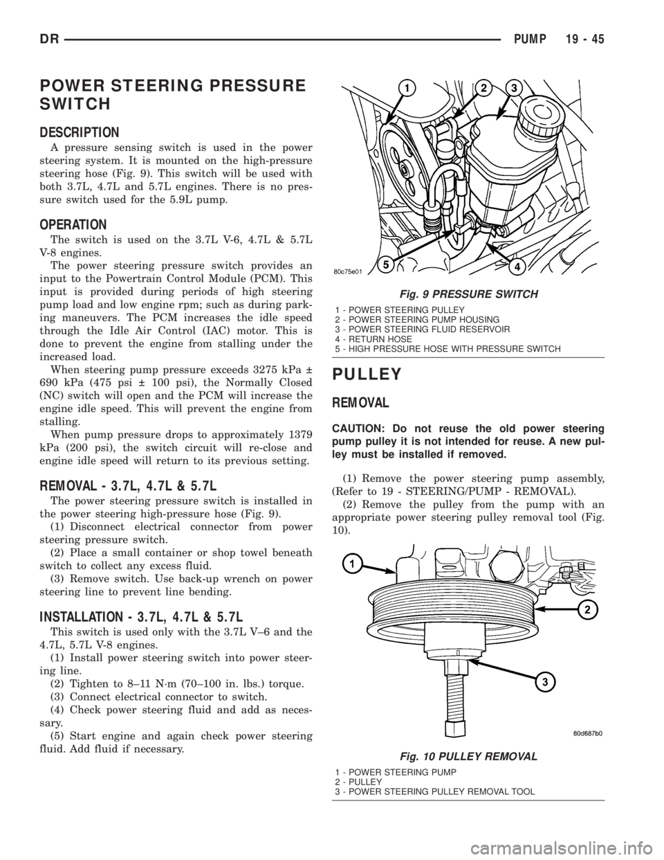
A pressure sensing switch is used in the power
steering system. It is mounted on the high-pressure
steering hose (Fig. 9). This switch will be used with
both 3.7L, 4.7L and 5.7L engines. There is no pres-
sure switch used for the 5.9L pump.
OPERATION
The switch is used on the 3.7L V-6, 4.7L & 5.7L
V-8 engines.
The power steering pressure switch provides an
input to the Powertrain Control Module (PCM). This
input is provided during periods of high steering
pump load and low engine rpm; such as during park-
ing maneuvers. The PCM increases the idle speed
through the Idle Air Control (IAC) motor. This is
done to prevent the engine from stalling under the
increased load.
When steering pump pressure exceeds 3275 kPa
690 kPa (475 psi 100 psi), the Normally Closed
(NC) switch will open and the PCM will increase the
engine idle speed. This will prevent the engine from
stalling.
When pump pressure drops to approximately 1379
kPa (200 psi), the switch circuit will re-close and
engine idle speed will return to its previous setting.
REMOVAL - 3.7L, 4.7L & 5.7L
The power steering pressure switch is installed in
the power steering high-pressure hose (Fig. 9).
(1) Disconnect electrical connector from power
steering pressure switch.
(2) Place a small container or shop towel beneath
switch to collect any excess fluid.
(3) Remove switch. Use back-up wrench on power
steering line to prevent line bending.
INSTALLATION - 3.7L, 4.7L & 5.7L
This switch is used only with the 3.7L V±6 and the
4.7L, 5.7L V-8 engines.
(1) Install power steering switch into power steer-
ing line.
(2) Tighten to 8±11 N´m (70±100 in. lbs.) torque.
(3) Connect electrical connector to switch.
(4) Check power steering fluid and add as neces-
sary.
(5) Start engine and again check power steering
fluid. Add fluid if necessary.
PULLEY
REMOVAL
CAUTION: Do not reuse the old power steering
pump pulley it is not intended for reuse. A new pul-
ley must be installed if removed.
(1) Remove the power steering pump assembly,
(Refer to 19 - STEERING/PUMP - REMOVAL).
(2) Remove the pulley from the pump with an
appropriate power steering pulley removal tool (Fig.
10).
Fig. 9 PRESSURE SWITCH
1 - POWER STEERING PULLEY
2 - POWER STEERING PUMP HOUSING
3 - POWER STEERING FLUID RESERVOIR
4 - RETURN HOSE
5 - HIGH PRESSURE HOSE WITH PRESSURE SWITCH
Fig. 10 PULLEY REMOVAL
1 - POWER STEERING PUMP
2 - PULLEY
3 - POWER STEERING PULLEY REMOVAL TOOL
DRPUMP 19 - 45
Page 1969 of 2895
CLEANING...........................214
INSPECTION.........................214
ASSEMBLY...........................215
OUTPUT SHAFT FRONT BEARING
REMOVAL............................217
INSTALLATION........................217
OUTPUT SHAFT REAR BEARING
REMOVAL............................217
INSTALLATION........................217
OVERDRIVE CLUTCH
DESCRIPTION........................218
OPERATION..........................218
OVERDRIVE SWITCH
DESCRIPTION........................218
OPERATION..........................218
DIAGNOSIS AND TESTING - OVERDRIVE
ELECTRICAL CONTROLS..............219
REMOVAL............................219
INSTALLATION........................219
OVERDRIVE UNIT
REMOVAL............................220
DISASSEMBLY........................220
CLEANING...........................227
INSPECTION.........................227
ASSEMBLY...........................228
INSTALLATION........................236
OVERRUNNING CLUTCH CAM/OVERDRIVE
PISTON RETAINER
DESCRIPTION........................237
OPERATION..........................237
DISASSEMBLY........................238
CLEANING...........................238
INSPECTION.........................238
ASSEMBLY...........................239
PISTONS
DESCRIPTION........................241
OPERATION..........................241
PLANETARY GEARTRAIN/OUTPUT SHAFT
DESCRIPTION........................242
OPERATION..........................243
DISASSEMBLY........................243
INSPECTION.........................245
ASSEMBLY...........................245
REAR CLUTCH
DESCRIPTION........................248
OPERATION..........................249
DISASSEMBLY........................249
CLEANING...........................250
INSPECTION.........................250
ASSEMBLY...........................250REAR SERVO
DESCRIPTION........................252
OPERATION..........................252
DISASSEMBLY........................252
CLEANING...........................252
ASSEMBLY...........................253
SHIFT MECHANISM
DESCRIPTION........................253
OPERATION..........................253
SOLENOID
DESCRIPTION........................253
OPERATION..........................254
SPEED SENSOR
DESCRIPTION........................254
OPERATION..........................254
THROTTLE VALVE CABLE
DESCRIPTION........................254
ADJUSTMENTS - THROTTLE VALVE
CABLE.............................255
TORQUE CONVERTER
DESCRIPTION........................257
OPERATION..........................261
REMOVAL............................262
INSTALLATION........................262
TORQUE CONVERTER DRAINBACK VALVE
DESCRIPTION........................262
OPERATION..........................262
STANDARD PROCEDURE - TORQUE
CONVERTER DRAINBACK VALVE........262
TRANSMISSION RANGE SENSOR
DESCRIPTION........................263
OPERATION..........................263
DIAGNOSIS AND TESTING - TRANSMISSION
RANGE SENSOR (TRS)................264
REMOVAL............................265
INSTALLATION........................266
TRANSMISSION TEMPERATURE SENSOR
DESCRIPTION........................267
OPERATION..........................267
VALVE BODY
DESCRIPTION........................267
OPERATION..........................272
REMOVAL............................286
DISASSEMBLY........................287
CLEANING...........................298
INSPECTION.........................298
ASSEMBLY...........................299
INSTALLATION........................307
ADJUSTMENTS - VALVE BODY...........308
21 - 130 AUTOMATIC TRANSMISSION - 46REDR
Page 1978 of 2895
FOURTH GEAR POWERFLOW
Fourth gear overdrive range is electronically con-
trolled and hydraulically activated. Various sensor
inputs are supplied to the powertrain control module
to operate the overdrive solenoid on the valve body.
The solenoid contains a check ball that opens and
closes a vent port in the 3-4 shift valve feed passage.
The overdrive solenoid (and check ball) are not ener-
gized in first, second, third, or reverse gear. The vent
port remains open, diverting line pressure from the
2-3 shift valve away from the 3-4 shift valve. The
overdrive control switch must be in the ON position
to transmit overdrive status to the PCM. A 3-4
upshift occurs only when the overdrive solenoid is
energized by the PCM. The PCM energizes the over-
drive solenoid during the 3-4 upshift. This causes the
solenoid check ball to close the vent port allowing
line pressure from the 2-3 shift valve to act directly
on the 3-4 upshift valve. Line pressure on the 3-4
shift valve overcomes valve spring pressure moving
the valve to the upshift position. This action exposes
the feed passages to the 3-4 timing valve, 3-4 quick
fill valve, 3-4 accumulator, and ultimately to the
overdrive piston. Line pressure through the timing
valve moves the overdrive piston into contact with
the overdrive clutch. The direct clutch is disengaged
before the overdrive clutch is engaged. The boost
valve provides increased fluid apply pressure to the
overdrive clutch during 3-4 upshifts, and when accel-
erating in fourth gear. The 3-4 accumulator cushions
overdrive clutch engagement to smooth 3-4 upshifts.
The accumulator is charged at the same time as
apply pressure acts against the overdrive piston.
DIAGNOSIS AND TESTING
DIAGNOSIS AND TESTING - AUTOMATIC
TRANSMISSION
Automatic transmission problems can be a result of
poor engine performance, incorrect fluid level, incor-
rect linkage or cable adjustment, band or hydraulic
control pressure adjustments, hydraulic system mal-
functions or electrical/mechanical component mal-
functions. Begin diagnosis by checking the easily
accessible items such as: fluid level and condition,
linkage adjustments and electrical connections. A
road test will determine if further diagnosis is neces-
sary.
DIAGNOSIS AND TESTING - PRELIMINARY
Two basic procedures are required. One procedure
for vehicles that are drivable and an alternate proce-
dure for disabled vehicles (will not back up or move
forward).
VEHICLE IS DRIVEABLE
(1) Check for transmission fault codes using DRBt
scan tool.
(2) Check fluid level and condition.
(3) Adjust throttle and gearshift linkage if com-
plaint was based on delayed, erratic, or harsh shifts.
(4) Road test and note how transmission upshifts,
downshifts, and engages.
(5) Perform hydraulic pressure test if shift prob-
lems were noted during road test.
(6) Perform air-pressure test to check clutch-band
operation.
VEHICLE IS DISABLED
(1) Check fluid level and condition.
(2) Check for broken or disconnected gearshift or
throttle linkage.
(3) Check for cracked, leaking cooler lines, or loose
or missing pressure-port plugs.
(4) Raise and support vehicle on safety stands,
start engine, shift transmission into gear, and note
following:
(a) If propeller shaft turns but wheels do not,
problem is with differential or axle shafts.
(b) If propeller shaft does not turn and transmis-
sion is noisy, stop engine. Remove oil pan, and
check for debris. If pan is clear, remove transmis-
sion and check for damaged drive plate, converter,
oil pump, or input shaft.
(c) If propeller shaft does not turn and transmis-
sion is not noisy, perform hydraulic-pressure test to
determine if problem is hydraulic or mechanical.
DIAGNOSIS AND TESTING - ROAD TESTING
Before road testing, be sure the fluid level and con-
trol cable adjustments have been checked and
adjusted if necessary. Verify that diagnostic trouble
codes have been resolved.
Observe engine performance during the road test.
A poorly tuned engine will not allow accurate analy-
sis of transmission operation.
Operate the transmission in all gear ranges. Check
for shift variations and engine flare which indicates
slippage. Note if shifts are harsh, spongy, delayed,
early, or if part throttle downshifts are sensitive.
Slippage indicated by engine flare, usually means
clutch, band or overrunning clutch problems. If the
condition is advanced, an overhaul will be necessary
to restore normal operation.
A slipping clutch or band can often be determined
by comparing which internal units are applied in the
various gear ranges. The Clutch and Band Applica-
tion chart provides a basis for analyzing road test
results.
DRAUTOMATIC TRANSMISSION - 46RE 21 - 139
AUTOMATIC TRANSMISSION - 46RE (Continued)
Page 1984 of 2895
DIAGNOSIS CHARTS
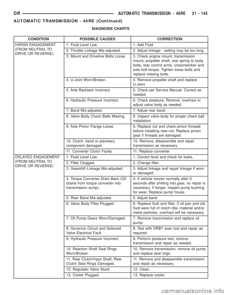
CONDITION POSSIBLE CAUSES CORRECTION
HARSH ENGAGEMENT
(FROM NEUTRAL TO
DRIVE OR REVERSE)1. Fluid Level Low. 1. Add Fluid
2. Throttle Linkage Mis-adjusted. 2. Adjust linkage - setting may be too long.
3. Mount and Driveline Bolts Loose. 3. Check engine mount, transmission
mount, propeller shaft, rear spring to body
bolts, rear control arms, crossmember and
axle bolt torque. Tighten loose bolts and
replace missing bolts.
4. U-Joint Worn/Broken. 4. Remove propeller shaft and replace
U-Joint.
5. Axle Backlash Incorrect. 5. Check per Service Manual. Correct as
needed.
6. Hydraulic Pressure Incorrect. 6. Check pressure. Remove, overhaul or
adjust valve body as needed.
7. Band Mis-adjusted. 7. Adjust rear band.
8. Valve Body Check Balls Missing. 8. Inspect valve body for proper check ball
installation.
9. Axle Pinion Flange Loose. 9. Replace nut and check pinion threads
before installing new nut. Replace pinion
gear if threads are damaged.
10. Clutch, band or planetary
component damaged.10. Remove, disassemble and repair
transmission as necessary.
11. Converter Clutch Faulty. 11. Replace converter.
DELAYED ENGAGEMENT
(FROM NEUTRAL TO
DRIVE OR REVERSE)1. Fluid Level Low. 1. Correct level and check for leaks.
2. Filter Clogged. 2. Change filter.
3. Gearshift Linkage Mis-adjusted. 3. Adjust linkage and repair linkage if worn
or damaged.
4. Torque Converter Drain Back (Oil
drains from torque converter into
transmission sump).4. If vehicle moves normally after 5
seconds after shifting into gear, no repair is
necessary. If longer, inspect pump bushing
for wear. Replace pump house.
5. Rear Band Mis-adjusted. 5. Adjust band.
6. Valve Body Filter Plugged. 6. Replace fluid and filter. If oil pan and old
fluid were full of clutch disc material and/or
metal particles, overhaul will be necessary.
7. Oil Pump Gears Worn/Damaged. 7. Remove transmission and replace oil
pump.
8. Governor Circuit and Solenoid
Valve Electrical Fault.8. Test with DRBTscan tool and repair as
required.
9. Hydraulic Pressure Incorrect. 9. Perform pressure test, remove
transmission and repair as needed.
10. Reaction Shaft Seal Rings
Worn/Broken.10. Remove transmission, remove oil pump
and replace seal rings.
11. Rear Clutch/Input Shaft, Rear
Clutch Seal Rings Damaged.11. Remove and disassemble transmission
and repair as necessary.
12. Regulator Valve Stuck. 12. Clean.
13. Cooler Plugged. 13. Replace cooler.
DRAUTOMATIC TRANSMISSION - 46RE 21 - 145
AUTOMATIC TRANSMISSION - 46RE (Continued)