Page 594 of 1767
Description
SYSTEM DESCRIPTION
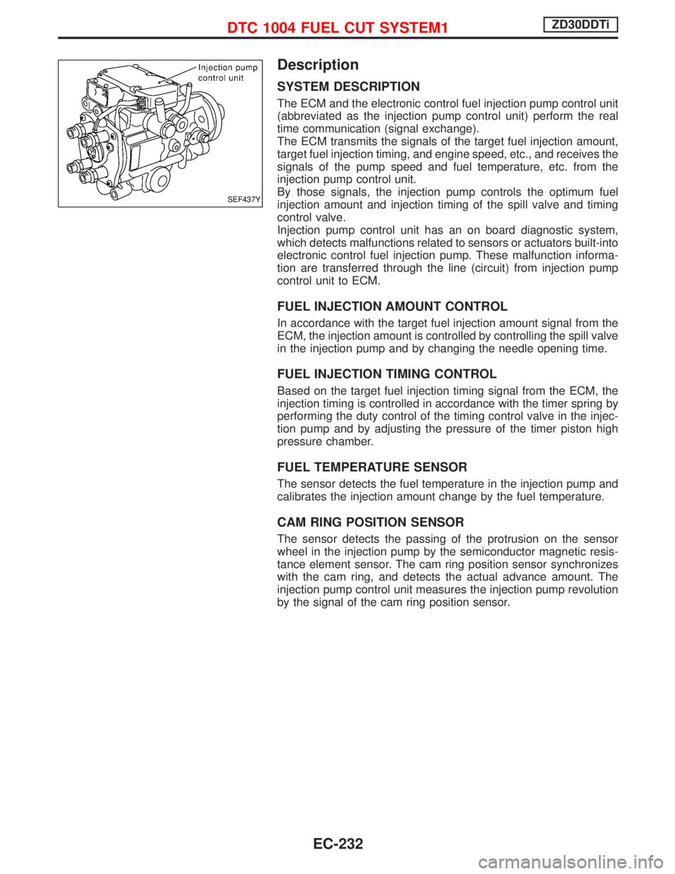
The ECM and the electronic control fuel injection pump control unit
(abbreviated as the injection pump control unit) perform the real
time communication (signal exchange).
The ECM transmits the signals of the target fuel injection amount,
target fuel injection timing, and engine speed, etc., and receives the
signals of the pump speed and fuel temperature, etc. from the
injection pump control unit.
By those signals, the injection pump controls the optimum fuel
injection amount and injection timing of the spill valve and timing
control valve.
Injection pump control unit has an on board diagnostic system,
which detects malfunctions related to sensors or actuators built-into
electronic control fuel injection pump. These malfunction informa-
tion are transferred through the line (circuit) from injection pump
control unit to ECM.
FUEL INJECTION AMOUNT CONTROL
In accordance with the target fuel injection amount signal from the
ECM, the injection amount is controlled by controlling the spill valve
in the injection pump and by changing the needle opening time.
FUEL INJECTION TIMING CONTROL
Based on the target fuel injection timing signal from the ECM, the
injection timing is controlled in accordance with the timer spring by
performing the duty control of the timing control valve in the injec-
tion pump and by adjusting the pressure of the timer piston high
pressure chamber.
FUEL TEMPERATURE SENSOR
The sensor detects the fuel temperature in the injection pump and
calibrates the injection amount change by the fuel temperature.
CAM RING POSITION SENSOR
The sensor detects the passing of the protrusion on the sensor
wheel in the injection pump by the semiconductor magnetic resis-
tance element sensor. The cam ring position sensor synchronizes
with the cam ring, and detects the actual advance amount. The
injection pump control unit measures the injection pump revolution
by the signal of the cam ring position sensor.
SEF437Y
DTC 1004 FUEL CUT SYSTEM1ZD30DDTi
EC-232
Page 595 of 1767
CONSULT-II Reference Value in Data Monitor
Mode
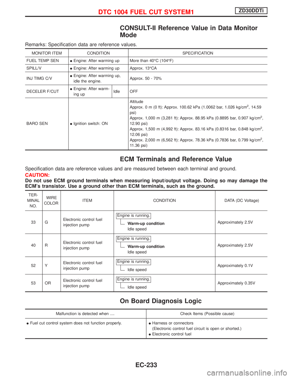
Remarks: Specification data are reference values.
MONITOR ITEM CONDITION SPECIFICATION
FUEL TEMP SENIEngine: After warming up More than 40ÉC (104ÉF)
SPILL/VIEngine: After warming up Approx. 13ÉCA
INJ TIMG C/VIEngine: After warming up,
idle the engine.Approx. 50 - 70%
DECELER F/CUTIEngine: After warm-
ing upIdle OFF
BARO SENIIgnition switch: ONAltitude
Approx.0m(0ft): Approx. 100.62 kPa (1.0062 bar, 1.026 kg/cm
2, 14.59
psi)
Approx. 1,000 m (3,281 ft): Approx. 88.95 kPa (0.8895 bar, 0.907 kg/cm
2,
12.90 psi)
Approx. 1,500 m (4,992 ft): Approx. 83.16 kPa (0.8316 bar, 0.848 kg/cm
2,
12.06 psi)
Approx. 2,000 m (6,562 ft): Approx. 78.36 kPa (0.7836 bar, 0.799 kg/cm
2,
11.36 psi)
ECM Terminals and Reference Value
Specification data are reference values and are measured between each terminal and ground.
CAUTION:
Do not use ECM ground terminals when measuring input/output voltage. Doing so may damage the
ECM's transistor. Use a ground other than ECM terminals, such as the ground.
TER-
MINAL
NO.WIRE
COLORITEM CONDITION DATA (DC Voltage)
33 GElectronic control fuel
injection pumpEngine is running.
Warm-up condition
Idle speedApproximately 2.5V
40 RElectronic control fuel
injection pumpEngine is running.
Warm-up condition
Idle speedApproximately 2.5V
52 YElectronic control fuel
injection pumpEngine is running.
Idle speedApproximately 0.1V
53 ORElectronic control fuel
injection pumpEngine is running.
Idle speedApproximately 0.35V
On Board Diagnosis Logic
Malfunction is detected when .... Check Items (Possible cause)
IFuel cut control system does not function properly.IHarness or connectors
(Electronic control fuel circuit is open or shorted.)
IElectronic control fuel
DTC 1004 FUEL CUT SYSTEM1ZD30DDTi
EC-233
Page 599 of 1767
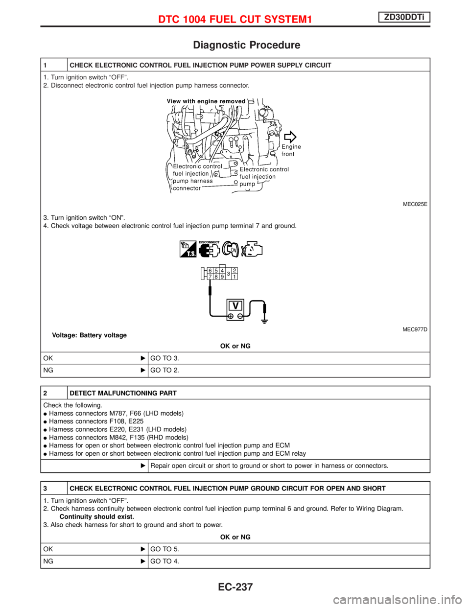
Diagnostic Procedure
1 CHECK ELECTRONIC CONTROL FUEL INJECTION PUMP POWER SUPPLY CIRCUIT
1. Turn ignition switch ªOFFº.
2. Disconnect electronic control fuel injection pump harness connector.
MEC025E
3. Turn ignition switch ªONº.
4. Check voltage between electronic control fuel injection pump terminal 7 and ground.
MEC977DVoltage: Battery voltage
OK or NG
OKEGO TO 3.
NGEGO TO 2.
2 DETECT MALFUNCTIONING PART
Check the following.
IHarness connectors M787, F66 (LHD models)
IHarness connectors F108, E225
IHarness connectors E220, E231 (LHD models)
IHarness connectors M842, F135 (RHD models)
IHarness for open or short between electronic control fuel injection pump and ECM
IHarness for open or short between electronic control fuel injection pump and ECM relay
ERepair open circuit or short to ground or short to power in harness or connectors.
3 CHECK ELECTRONIC CONTROL FUEL INJECTION PUMP GROUND CIRCUIT FOR OPEN AND SHORT
1. Turn ignition switch ªOFFº.
2. Check harness continuity between electronic control fuel injection pump terminal 6 and ground. Refer to Wiring Diagram.
Continuity should exist.
3. Also check harness for short to ground and short to power.
OK or NG
OKEGO TO 5.
NGEGO TO 4.
DTC 1004 FUEL CUT SYSTEM1ZD30DDTi
EC-237
Page 600 of 1767
4 DETECT MALFUNCTIONING PART
Check the following.
IHarness connectors E231, E220
IHarness for open or short between electronic control fuel injection pump and engine ground
ERepair open circuit or short to ground or short to power in harness or connectors.
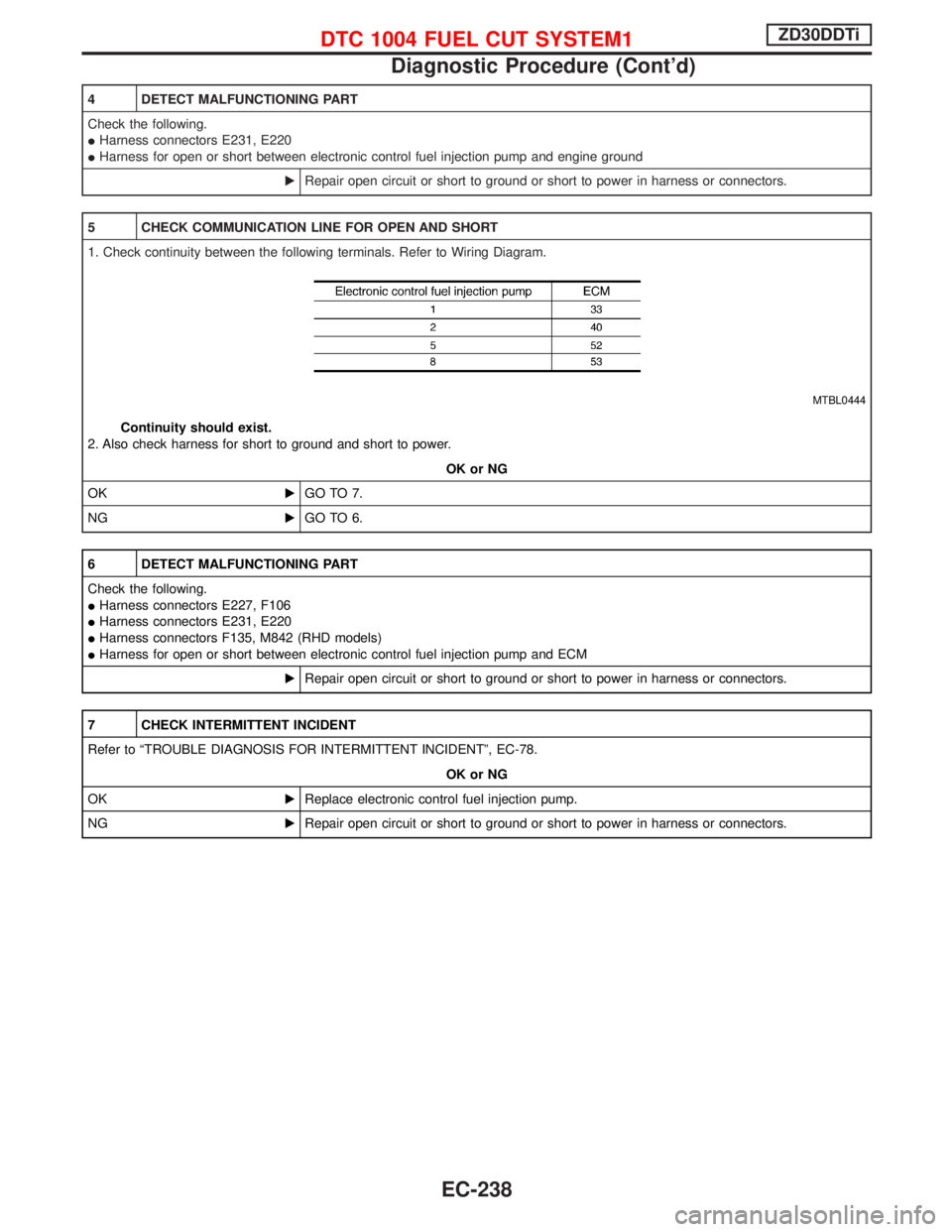
5 CHECK COMMUNICATION LINE FOR OPEN AND SHORT
1. Check continuity between the following terminals. Refer to Wiring Diagram.
MTBL0444
Continuity should exist.
2. Also check harness for short to ground and short to power.
OK or NG
OKEGO TO 7.
NGEGO TO 6.
6 DETECT MALFUNCTIONING PART
Check the following.
IHarness connectors E227, F106
IHarness connectors E231, E220
IHarness connectors F135, M842 (RHD models)
IHarness for open or short between electronic control fuel injection pump and ECM
ERepair open circuit or short to ground or short to power in harness or connectors.
7 CHECK INTERMITTENT INCIDENT
Refer to ªTROUBLE DIAGNOSIS FOR INTERMITTENT INCIDENTº, EC-78.
OK or NG
OKEReplace electronic control fuel injection pump.
NGERepair open circuit or short to ground or short to power in harness or connectors.
DTC 1004 FUEL CUT SYSTEM1ZD30DDTi
Diagnostic Procedure (Cont'd)
EC-238
Page 654 of 1767
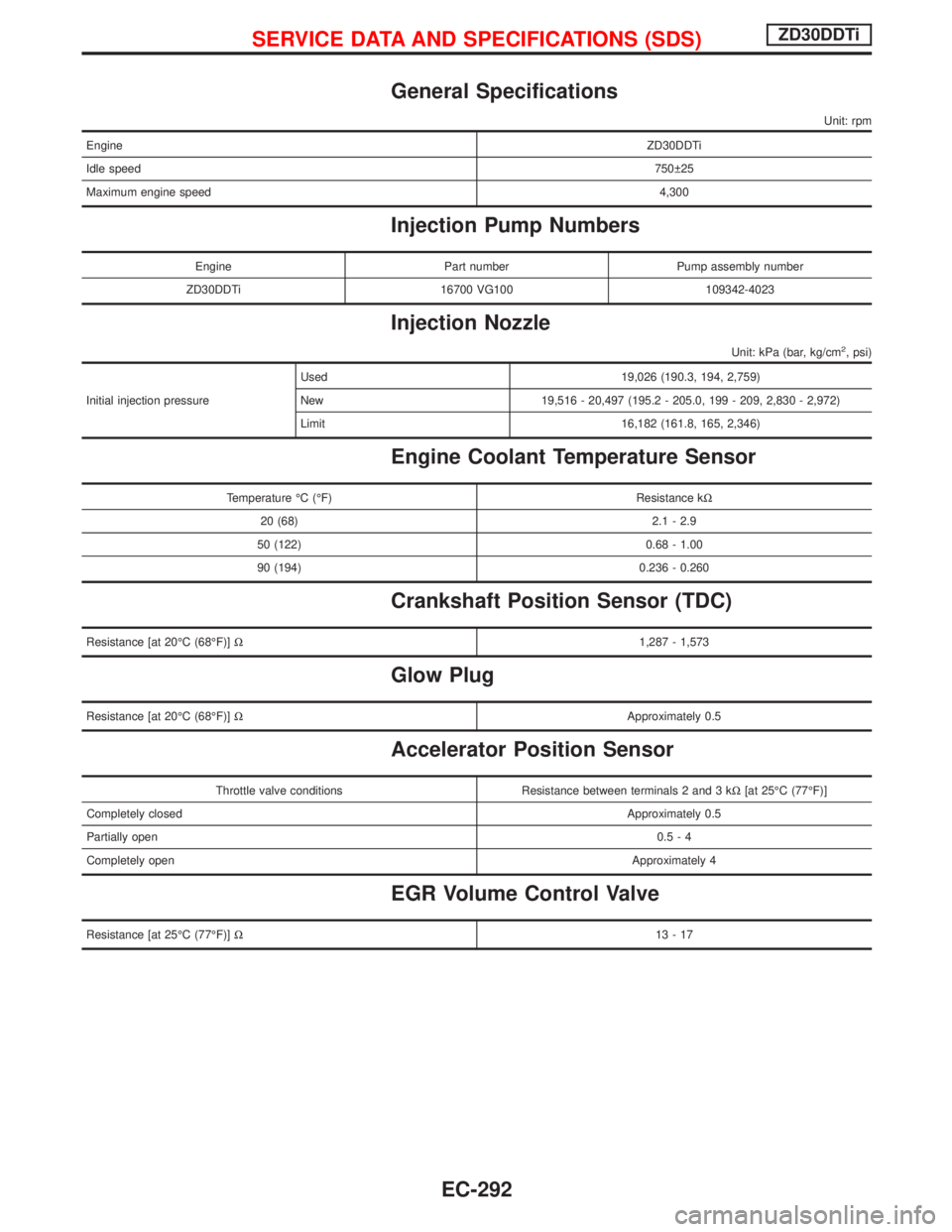
General Specifications
Unit: rpm
EngineZD30DDTi
Idle speed750 25
Maximum engine speed4,300
Injection Pump Numbers
Engine Part number Pump assembly number
ZD30DDTi 16700 VG100 109342-4023
Injection Nozzle
Unit: kPa (bar, kg/cm2, psi)
Initial injection pressureUsed 19,026 (190.3, 194, 2,759)
New 19,516 - 20,497 (195.2 - 205.0, 199 - 209, 2,830 - 2,972)
Limit 16,182 (161.8, 165, 2,346)
Engine Coolant Temperature Sensor
Temperature ÉC (ÉF) Resistance kW
20 (68) 2.1 - 2.9
50 (122) 0.68 - 1.00
90 (194) 0.236 - 0.260
Crankshaft Position Sensor (TDC)
Resistance [at 20ÉC (68ÉF)]W1,287 - 1,573
Glow Plug
Resistance [at 20ÉC (68ÉF)]WApproximately 0.5
Accelerator Position Sensor
Throttle valve conditions Resistance between terminals 2 and 3 kW[at 25ÉC (77ÉF)]
Completely closedApproximately 0.5
Partially open0.5-4
Completely openApproximately 4
EGR Volume Control Valve
Resistance [at 25ÉC (77ÉF)]W13-17
SERVICE DATA AND SPECIFICATIONS (SDS)ZD30DDTi
EC-292
Page 657 of 1767
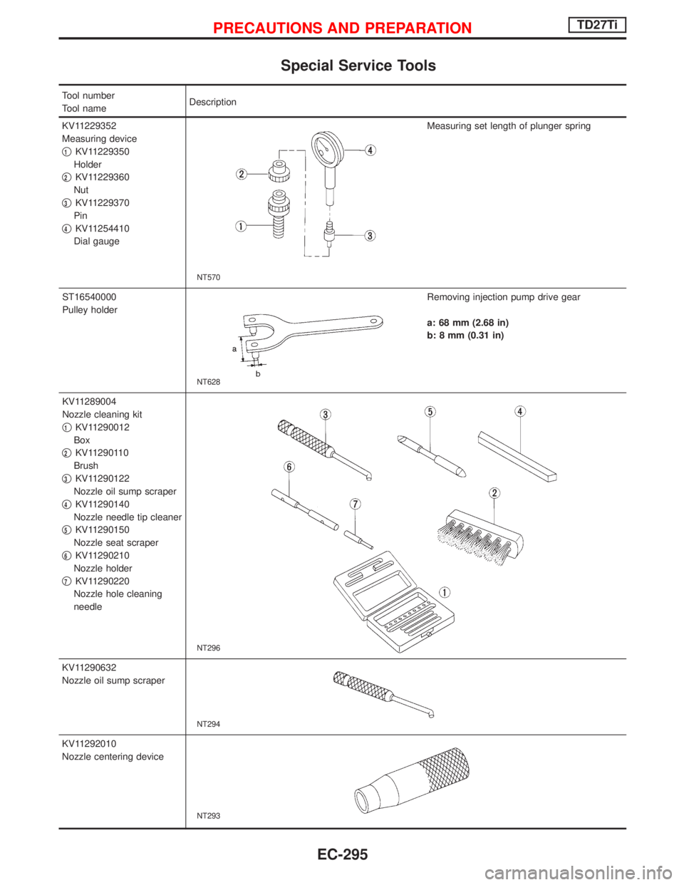
Special Service Tools
Tool number
Tool nameDescription
KV11229352
Measuring device
q
1KV11229350
Holder
q
2KV11229360
Nut
q
3KV11229370
Pin
q
4KV11254410
Dial gauge
NT570
Measuring set length of plunger spring
ST16540000
Pulley holder
NT628
Removing injection pump drive gear
a: 68 mm (2.68 in)
b: 8 mm (0.31 in)
KV11289004
Nozzle cleaning kit
q
1KV11290012
Box
q
2KV11290110
Brush
q
3KV11290122
Nozzle oil sump scraper
q
4KV11290140
Nozzle needle tip cleaner
q
5KV11290150
Nozzle seat scraper
q
6KV11290210
Nozzle holder
q
7KV11290220
Nozzle hole cleaning
needle
NT296
KV11290632
Nozzle oil sump scraper
NT294
KV11292010
Nozzle centering device
NT293
PRECAUTIONS AND PREPARATIONTD27Ti
EC-295
Page 668 of 1767
Fuel Injection System
SYSTEM DESCRIPTION
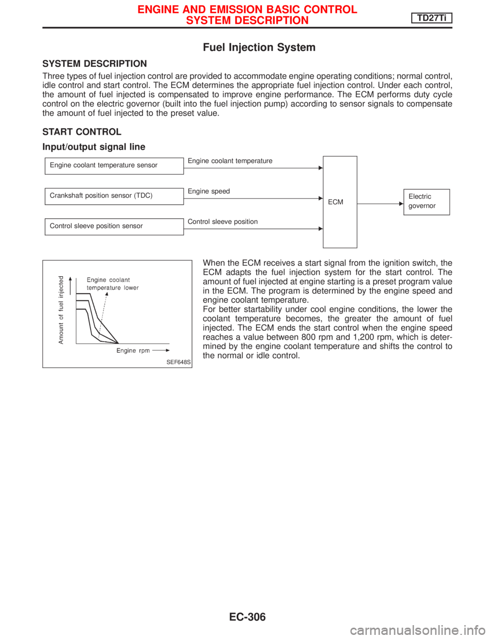
Three types of fuel injection control are provided to accommodate engine operating conditions; normal control,
idle control and start control. The ECM determines the appropriate fuel injection control. Under each control,
the amount of fuel injected is compensated to improve engine performance. The ECM performs duty cycle
control on the electric governor (built into the fuel injection pump) according to sensor signals to compensate
the amount of fuel injected to the preset value.
START CONTROL
Input/output signal line
Engine coolant temperature sensorEEngine coolant temperature
ECM
EElectric
governorCrankshaft position sensor (TDC)EEngine speed
Control sleeve position sensor
EControl sleeve position
When the ECM receives a start signal from the ignition switch, the
ECM adapts the fuel injection system for the start control. The
amount of fuel injected at engine starting is a preset program value
in the ECM. The program is determined by the engine speed and
engine coolant temperature.
For better startability under cool engine conditions, the lower the
coolant temperature becomes, the greater the amount of fuel
injected. The ECM ends the start control when the engine speed
reaches a value between 800 rpm and 1,200 rpm, which is deter-
mined by the engine coolant temperature and shifts the control to
the normal or idle control.
SEF648S
ENGINE AND EMISSION BASIC CONTROL
SYSTEM DESCRIPTIONTD27Ti
EC-306
Page 670 of 1767
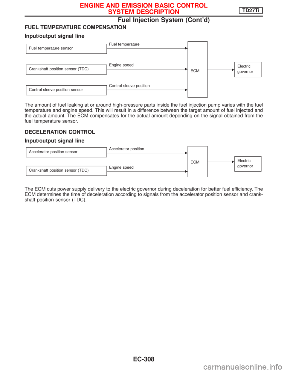
FUEL TEMPERATURE COMPENSATION
Input/output signal line
Fuel temperature sensorEFuel temperature
ECM
EElectric
governorCrankshaft position sensor (TDC)EEngine speed
Control sleeve position sensor
EControl sleeve position
The amount of fuel leaking at or around high-pressure parts inside the fuel injection pump varies with the fuel
temperature and engine speed. This will result in a difference between the target amount of fuel injected and
the actual amount. The ECM compensates for the actual amount depending on the signal obtained from the
fuel temperature sensor.
DECELERATION CONTROL
Input/output signal line
Accelerator position sensorEAccelerator position
ECM
EElectric
governor
Crankshaft position sensor (TDC)EEngine speed
The ECM cuts power supply delivery to the electric governor during deceleration for better fuel efficiency. The
ECM determines the time of deceleration according to signals from the accelerator position sensor and crank-
shaft position sensor (TDC).
ENGINE AND EMISSION BASIC CONTROL
SYSTEM DESCRIPTIONTD27Ti
Fuel Injection System (Cont'd)
EC-308