2002 NISSAN TERRANO Injection pump
[x] Cancel search: Injection pumpPage 701 of 1767
qA
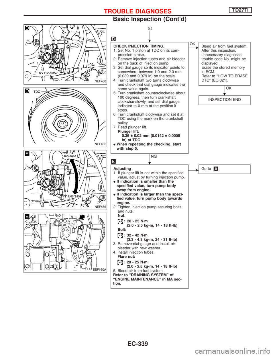
CHECK INJECTION TIMING.
1. Set No. 1 piston at TDC on its com-
pression stroke.
2. Remove injection tubes and air bleeder
on the back of injection pump.
3. Set dial gauge so its indicator points to
somewhere between 1.0 and 2.0 mm
(0.039 and 0.079 in) on the scale.
4. Turn crankshaft two turns clockwise
and check that dial gauge indicates the
same value again.
5. Turn crankshaft counterclockwise about
100 degrees, then turn crankshaft
clockwise slowly, and set dial gauge
indicator to 0 mm at the position it
stops.
6. Turn crankshaft clockwise and set it at
TDC using the mark on the crankshaft
pulley.
7. Read plunger lift.
Plunger lift:
0.36 0.02 mm (0.0142 0.0008
in) at TDC
IWhen repeating the checking, start
with step 5.
NG
EOK
Bleed air from fuel system.
After this inspection,
unnecessary diagnostic
trouble code No. might be
displayed.
Erase the stored memory
in ECM.
Refer to ªHOW TO ERASE
DTCº (EC-321).
OK
INSPECTION END
Adjusting
1. If plunger lift is not within the specified
value, adjust by turning injection pump.
IIf indication is smaller than the
specified value, turn pump body
away from engine.
IIf indication is larger than the speci-
fied value, turn pump body towards
engine.
2. Tighten injection pump securing bolts
and nuts.
Nut:
: 20-25N×m
(2.0 - 2.5 kg-m, 14 - 18 ft-lb)
Bolt:
: 32-42N×m
(3.3 - 4.3 kg-m, 24 - 31 ft-lb)
3. Remove dial gauge and install air
bleeder with new washer.
4. Install injection tubes.
Flare nut:
: 20-25N×m
(2.0 - 2.5 kg-m, 14 - 18 ft-lb)
5. Bleed air from fuel system.
Refer to ªDRAINING SYSTEMº of
ªENGINE MAINTENANCEº in MA sec-
tion.
EGo to.
NEF468
NEF465
NEF466
EEF160A
H
H
H
TROUBLE DIAGNOSESTD27Ti
Basic Inspection (Cont'd)
EC-339
Page 702 of 1767
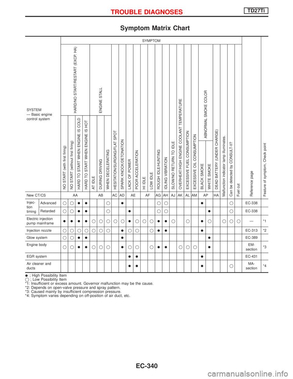
Symptom Matrix Chart
SYSTEM
Ð Basic engine
control systemSYMPTOM
Reference page
Feature of symptom, Check pointHARD/NO START/RESTART (EXCP. HA)
ENGINE STALL
HESITATION/SURGING/FLAT SPOT
SPARK KNOCK/DETONATION
LACK OF POWER
POOR ACCELERATION
HI IDLE
LOW IDLE
ROUGH IDLE/HUNTING
IDLING VIBRATION
SLOW/NO RETURN TO IDLE
OVERHEAT/HIGH ENGINE COOLANT TEMPERATURE
EXCESSIVE FUEL CONSUMPTION
EXCESSIVE OIL CONSUMPTION
ABNORMAL SMOKE COLOR
DEAD BATTERY (UNDER CHARGE)
Malfunction indicator lamp illuminates.
Can be detected by CONSULT-II?
Fuel cutNO START (with first firing)
NO START (without first firing)
HARD TO START WHEN ENGINE IS COLD
HARD TO START WHEN ENGINE IS HOT
AT IDLE
DURING DRIVING
WHEN DECELERATING
BLACK SMOKE
WHITE SMOKENew CT/CS AA AB AC AD AE AF AG AH AJ AK AL AM AP HA
Injec-
tion
timingAdvancedqq
IIqIqqIqEC-338
Retardedqq
IIqIqqIqEC-338
Electric injection
pump mainframe
IIIIqqqqqIqqqIIqqIq qqqÐ*1
Injection nozzleqqqqqqq
Iqq qII IEC-313 *2
Glow systemqq
II I IEC-389
Engine body
qq
IIqqqIqq qIIqqqIEM-
section*3
EGR system
II IEC-431
Air cleaner and
ducts
II IqMA-
section*4
I; High Possibility Item
q; Low Possibility Item
*1: Insufficient or excess amount. Governor malfunction may be the cause.
*2: Depends on open-valve pressure and spray pattern.
*3: Caused mainly by insufficient compression pressure.
*4: Symptom varies depending on off-position of air duct, etc.
TROUBLE DIAGNOSESTD27Ti
EC-340
Page 734 of 1767
Component Description
FUEL TEMPERATURE SENSOR (FTS)
The fuel temperature sensor is used to detect the fuel temperature
in the injection pump. The sensor modifies a voltage signal from the
ECM. The modified signal returns to the ECM as the fuel tempera-
ture input. The sensor uses a thermistor which is sensitive to the
change in temperature. The electrical resistance of the thermistor
decreases as temperature increases.
The sensor is built into the inside electrical circuit of the injection
pump.
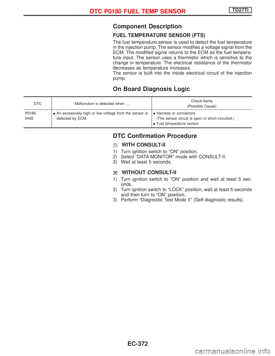
On Board Diagnosis Logic
DTC Malfunction is detected when ...Check Items
(Possible Cause)
P0180
0402IAn excessively high or low voltage from the sensor is
detected by ECM.IHarness or connectors
(The sensor circuit is open or short-circuited.)
IFuel temperature sensor
DTC Confirmation Procedure
WITH CONSULT-II
1) Turn ignition switch to ªONº position.
2) Select ªDATA MONITORº mode with CONSULT-II.
3) Wait at least 5 seconds.
WITHOUT CONSULT-II
1) Turn ignition switch to ªONº position and wait at least 5 sec-
onds.
2) Turn ignition switch to ªLOCKº position, wait at least 5 seconds
and then turn to ªONº position.
3) Perform ªDiagnostic Test Mode IIº (Self-diagnostic results).
DTC P0180 FUEL TEMP SENSORTD27Ti
EC-372
Page 736 of 1767
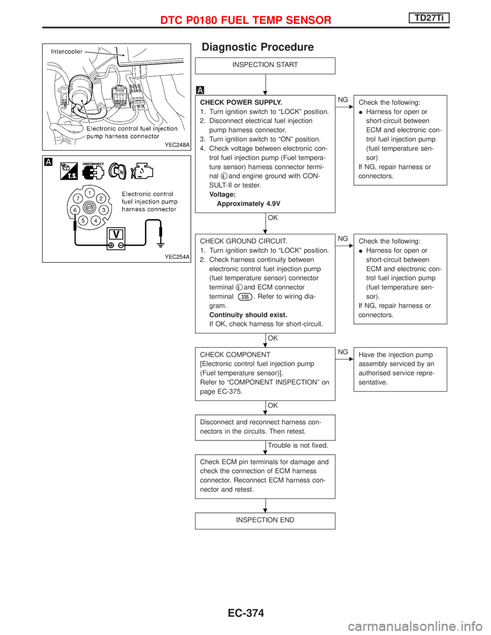
Diagnostic Procedure
INSPECTION START
CHECK POWER SUPPLY.
1. Turn ignition switch to ªLOCKº position.
2. Disconnect electrical fuel injection
pump harness connector.
3. Turn ignition switch to ªONº position.
4. Check voltage between electronic con-
trol fuel injection pump (Fuel tempera-
ture sensor) harness connector termi-
nalq
6and engine ground with CON-
SULT-II or tester.
Voltage:
Approximately 4.9V
OK
ENG
Check the following:
IHarness for open or
short-circuit between
ECM and electronic con-
trol fuel injection pump
(fuel temperature sen-
sor)
If NG, repair harness or
connectors.
CHECK GROUND CIRCUIT.
1. Turn ignition switch to ªLOCKº position.
2. Check harness continuity between
electronic control fuel injection pump
(fuel temperature sensor) connector
terminalq
5and ECM connector
terminal
335. Refer to wiring dia-
gram.
Continuity should exist.
If OK, check harness for short-circuit.
OK
ENG
Check the following:
IHarness for open or
short-circuit between
ECM and electronic con-
trol fuel injection pump
(fuel temperature sen-
sor).
If NG, repair harness or
connectors.
CHECK COMPONENT
[Electronic control fuel injection pump
(Fuel temperature sensor)].
Refer to ªCOMPONENT INSPECTIONº on
page EC-375.
OK
ENG
Have the injection pump
assembly serviced by an
authorised service repre-
sentative.
Disconnect and reconnect harness con-
nectors in the circuits. Then retest.
Trouble is not fixed.
Check ECM pin terminals for damage and
check the connection of ECM harness
connector. Reconnect ECM harness con-
nector and retest.
INSPECTION END
YEC248A
YEC254A
H
H
H
H
H
H
DTC P0180 FUEL TEMP SENSORTD27Ti
EC-374
Page 737 of 1767
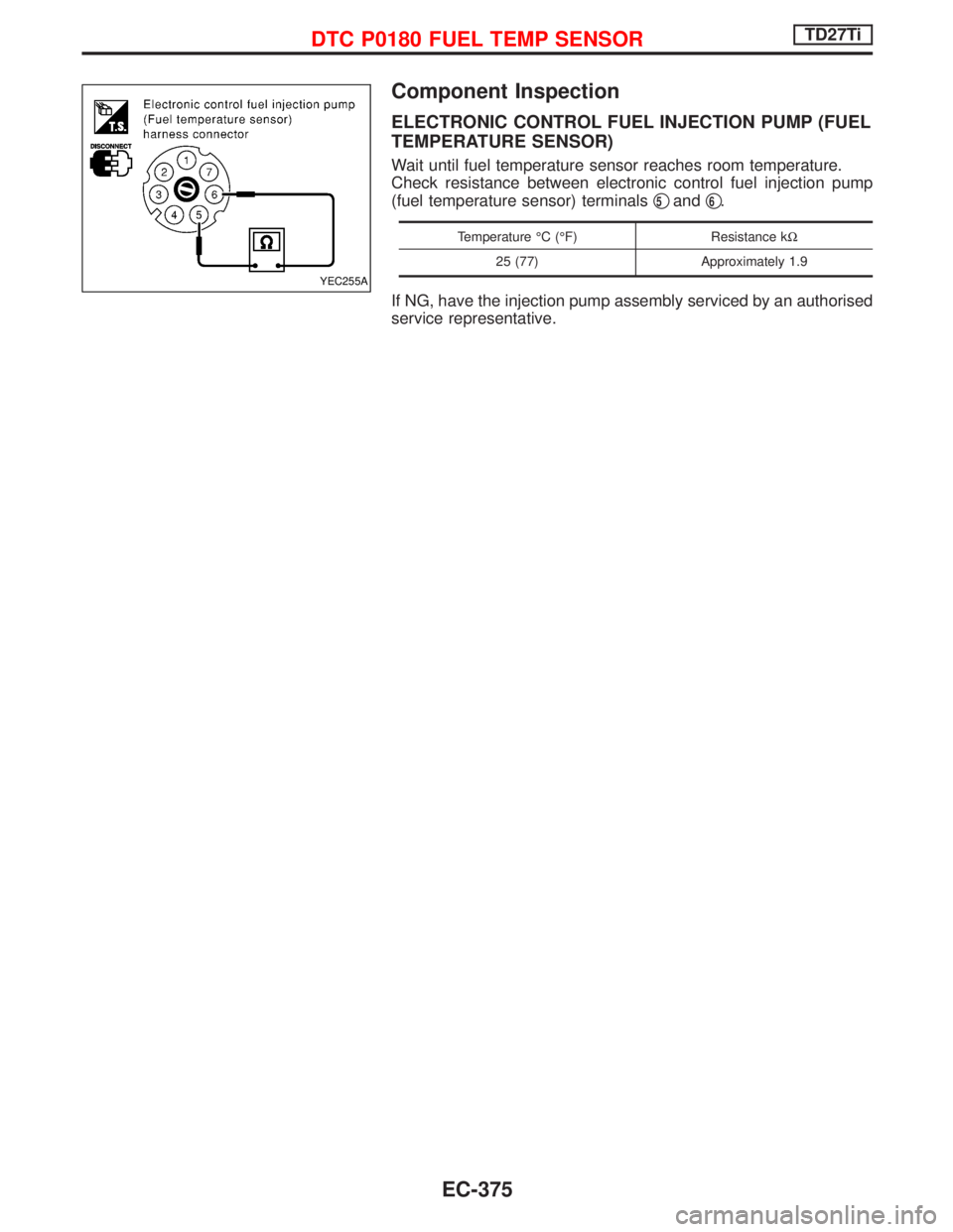
Component Inspection
ELECTRONIC CONTROL FUEL INJECTION PUMP (FUEL
TEMPERATURE SENSOR)
Wait until fuel temperature sensor reaches room temperature.
Check resistance between electronic control fuel injection pump
(fuel temperature sensor) terminalsq
5andq6.
Temperature ÉC (ÉF) Resistance kW
25 (77) Approximately 1.9
If NG, have the injection pump assembly serviced by an authorised
service representative.
YEC255A
DTC P0180 FUEL TEMP SENSORTD27Ti
EC-375
Page 742 of 1767
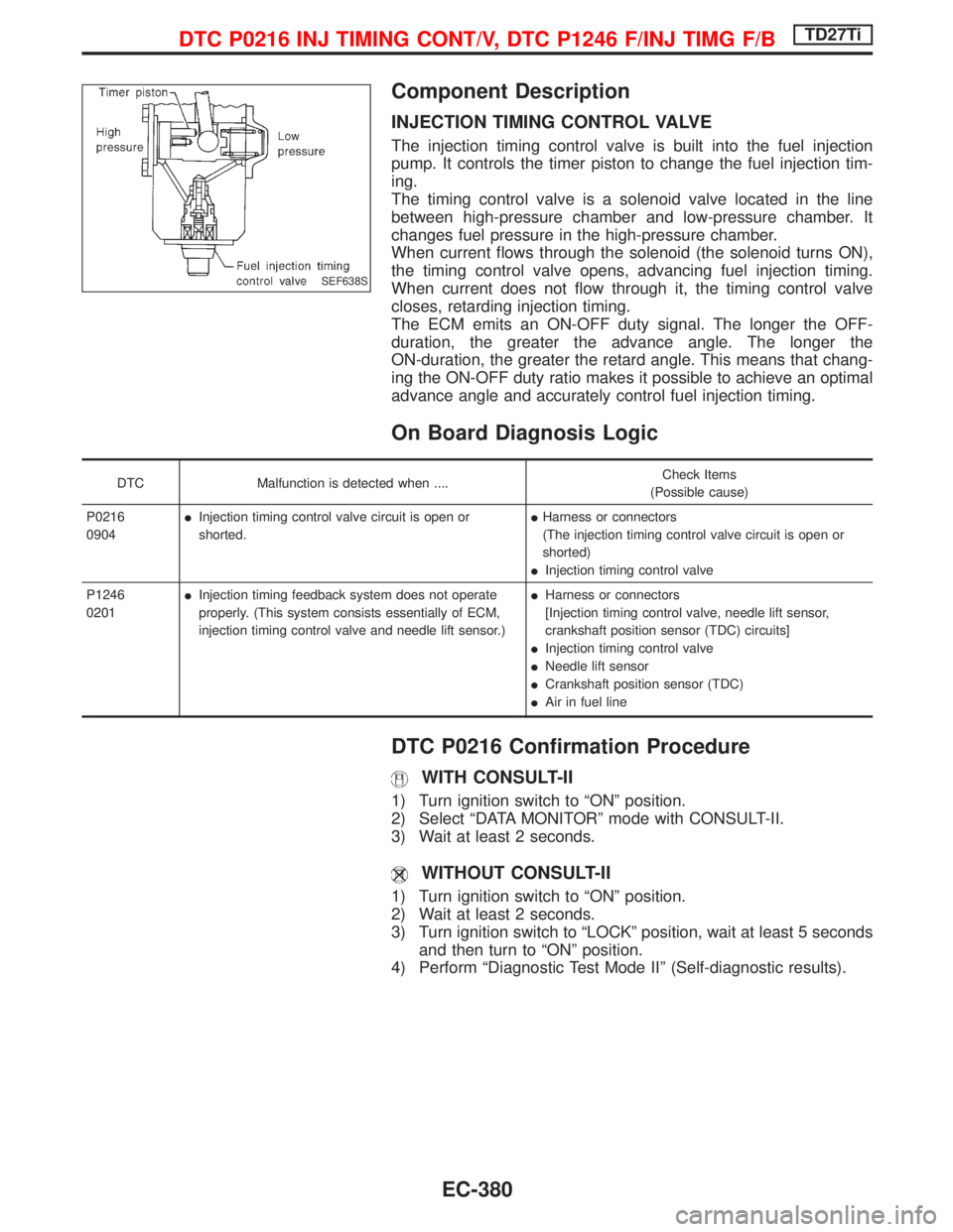
Component Description
INJECTION TIMING CONTROL VALVE
The injection timing control valve is built into the fuel injection
pump. It controls the timer piston to change the fuel injection tim-
ing.
The timing control valve is a solenoid valve located in the line
between high-pressure chamber and low-pressure chamber. It
changes fuel pressure in the high-pressure chamber.
When current flows through the solenoid (the solenoid turns ON),
the timing control valve opens, advancing fuel injection timing.
When current does not flow through it, the timing control valve
closes, retarding injection timing.
The ECM emits an ON-OFF duty signal. The longer the OFF-
duration, the greater the advance angle. The longer the
ON-duration, the greater the retard angle. This means that chang-
ing the ON-OFF duty ratio makes it possible to achieve an optimal
advance angle and accurately control fuel injection timing.
On Board Diagnosis Logic
DTC Malfunction is detected when ....Check Items
(Possible cause)
P0216
0904IInjection timing control valve circuit is open or
shorted.IHarness or connectors
(The injection timing control valve circuit is open or
shorted)
IInjection timing control valve
P1246
0201IInjection timing feedback system does not operate
properly. (This system consists essentially of ECM,
injection timing control valve and needle lift sensor.)IHarness or connectors
[Injection timing control valve, needle lift sensor,
crankshaft position sensor (TDC) circuits]
IInjection timing control valve
INeedle lift sensor
ICrankshaft position sensor (TDC)
IAir in fuel line
DTC P0216 Confirmation Procedure
WITH CONSULT-II
1) Turn ignition switch to ªONº position.
2) Select ªDATA MONITORº mode with CONSULT-II.
3) Wait at least 2 seconds.
WITHOUT CONSULT-II
1) Turn ignition switch to ªONº position.
2) Wait at least 2 seconds.
3) Turn ignition switch to ªLOCKº position, wait at least 5 seconds
and then turn to ªONº position.
4) Perform ªDiagnostic Test Mode IIº (Self-diagnostic results).
SEF638S
DTC P0216 INJ TIMING CONT/V, DTC P1246 F/INJ TIMG F/BTD27Ti
EC-380
Page 745 of 1767

Diagnostic Procedure
INSPECTION START
CHECK FOR AIR IN FUEL FILTER.
1. Move priming pump up and down to
purge air from fuel filter.
2. Perform ªDIAGNOSTIC TROUBLE
CODE CONFIRMATION PROCE-
DUREº.
CHECK POWER SUPPLY.
1. Turn ignition switch to ªLOCKº position.
2. Disconnect TVC and shut-off (injection
timing control valve) harness connec-
tor.
3. Turn ignition switch to ªONº position.
4. Check voltage between TVC and shut-
off (injection timing control valve) con-
nector terminalq
9and engine ground
with CONSULT-II or tester.
Voltage: Battery voltage
OK
ENG
Check the following:
IHarness connector
M787,F66
I20A fuse
IECM relay
IHarness for open or
short-circuit between
TVC and shut-off (injec-
tion timing control valve)
harness connector and
fuse box.
If NG, replace 20A fuse or
ECM relay, harness or con-
nectors.
CHECK OUTPUT SIGNAL CIRCUIT.
1. Turn ignition switch to ªLOCKº position.
2. Disconnect ECM harness connector.
3. Check harness continuity between TVC
and shut-off (injection timing control
valve) connector terminalq
8and ECM
terminals
202. Refer to wiring dia-
gram.
Continuity should exist.
If OK, check harness for short-circuit.
OK
ENG
Check the following:
IHarness for open or
short-circuit between
TVC and shut-off (injec-
tion timing control valve)
and ECM
If NG, repair harness or
connectors.
CHECK GROUND CIRCUIT.
1. Disconnect ECM harness connector.
2. Check harness continuity between
ECM connector terminal
349and TVC
and shut-off (injection timing control
valve) connector terminalq
10. Refer to
wiring diagram.
Continuity should exist.
If OK, check harness of short-circuit.
OK
ENG
Repair harness or connec-
tors
qA
YEC256A
NEF463
MEC947D
H
H
H
H
H
DTC P0216 INJ TIMING CONT/V, DTC P1246 F/INJ TIMG F/BTD27Ti
EC-383
Page 771 of 1767
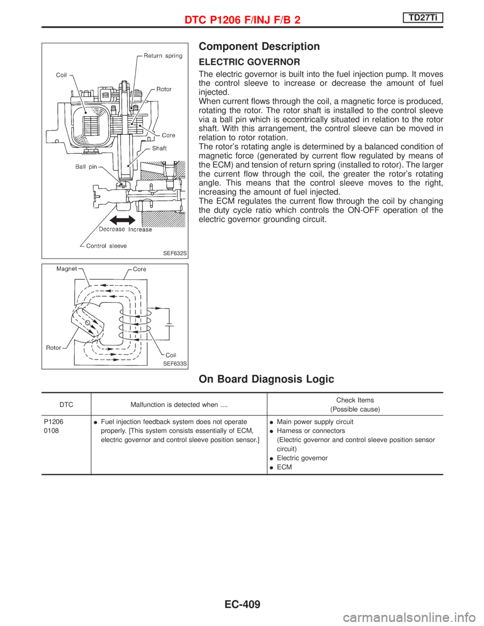
Component Description
ELECTRIC GOVERNOR
The electric governor is built into the fuel injection pump. It moves
the control sleeve to increase or decrease the amount of fuel
injected.
When current flows through the coil, a magnetic force is produced,
rotating the rotor. The rotor shaft is installed to the control sleeve
via a ball pin which is eccentrically situated in relation to the rotor
shaft. With this arrangement, the control sleeve can be moved in
relation to rotor rotation.
The rotor's rotating angle is determined by a balanced condition of
magnetic force (generated by current flow regulated by means of
the ECM) and tension of return spring (installed to rotor). The larger
the current flow through the coil, the greater the rotor's rotating
angle. This means that the control sleeve moves to the right,
increasing the amount of fuel injected.
The ECM regulates the current flow through the coil by changing
the duty cycle ratio which controls the ON-OFF operation of the
electric governor grounding circuit.
On Board Diagnosis Logic
DTC Malfunction is detected when ....Check Items
(Possible cause)
P1206
0108IFuel injection feedback system does not operate
properly. [This system consists essentially of ECM,
electric governor and control sleeve position sensor.]IMain power supply circuit
IHarness or connectors
(Electric governor and control sleeve position sensor
circuit)
IElectric governor
IECM
SEF632S
SEF633S
DTC P1206 F/INJ F/B 2TD27Ti
EC-409