Page 1118 of 1767
1. Warm up engine.
2. Turn ignition switch OFF.
3. Using CONSULT-II, make sure no error codes are indicated for
self-diagnosis items. Refer to EC section, ªFuel Pressure
Releaseº.
IDo not disconnect CONSULT-II until the end of this operation;
it will be used to check engine rpm and for error detection at
the end of this operation.
4. Disconnect the negative battery terminal.
5. Remove the following parts.
IIntercooler
IThrottle body
IRocker cover
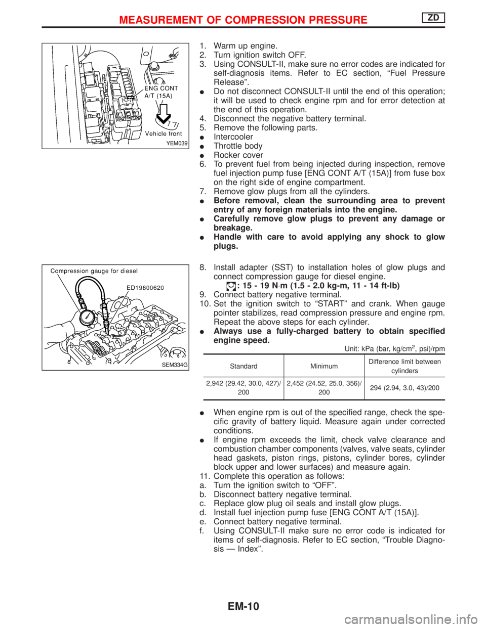
6. To prevent fuel from being injected during inspection, remove
fuel injection pump fuse [ENG CONT A/T (15A)] from fuse box
on the right side of engine compartment.
7. Remove glow plugs from all the cylinders.
IBefore removal, clean the surrounding area to prevent
entry of any foreign materials into the engine.
ICarefully remove glow plugs to prevent any damage or
breakage.
IHandle with care to avoid applying any shock to glow
plugs.
8. Install adapter (SST) to installation holes of glow plugs and
connect compression gauge for diesel engine.
:15-19N×m (1.5 - 2.0 kg-m, 11 - 14 ft-lb)
9. Connect battery negative terminal.
10. Set the ignition switch to ªSTARTº and crank. When gauge
pointer stabilizes, read compression pressure and engine rpm.
Repeat the above steps for each cylinder.
IAlways use a fully-charged battery to obtain specified
engine speed.
Unit: kPa (bar, kg/cm2, psi)/rpm
Standard MinimumDifference limit between
cylinders
2,942 (29.42, 30.0, 427)/
2002,452 (24.52, 25.0, 356)/
200294 (2.94, 3.0, 43)/200
IWhen engine rpm is out of the specified range, check the spe-
cific gravity of battery liquid. Measure again under corrected
conditions.
IIf engine rpm exceeds the limit, check valve clearance and
combustion chamber components (valves, valve seats, cylinder
head gaskets, piston rings, pistons, cylinder bores, cylinder
block upper and lower surfaces) and measure again.
11. Complete this operation as follows:
a. Turn the ignition switch to ªOFFº.
b. Disconnect battery negative terminal.
c. Replace glow plug oil seals and install glow plugs.
d. Install fuel injection pump fuse [ENG CONT A/T (15A)].
e. Connect battery negative terminal.
f. Using CONSULT-II make sure no error code is indicated for
items of self-diagnosis. Refer to EC section, ªTrouble Diagno-
sis Ð Indexº.
YEM039
SEM334G
MEASUREMENT OF COMPRESSION PRESSUREZD
EM-10
Page 1134 of 1767
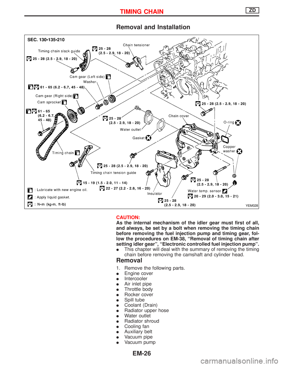
Removal and Installation
CAUTION:
As the internal mechanism of the idler gear must first of all,
and always, be set by a bolt when removing the timing chain
before removing the fuel injection pump and timing gear, fol-
low the procedures on EM-38, ªRemoval of timing chain after
setting idler gearº, ªElectronic controlled fuel injection pumpº.
IThis chapter will deal with the summary of removing the timing
chain before removing the camshaft and cylinder head.
Removal
1. Remove the following parts.
IEngine cover
IIntercooler
IAir inlet pipe
IThrottle body
IRocker cover
ISpill tube
ICoolant (Drain)
IRadiator upper hose
IWater outlet
IRadiator shroud
ICooling fan
IAuxiliary belt
IVacuum pipe
IVacuum pump
YEM028
TIMING CHAINZD
EM-26
Page 1147 of 1767
Removal
1. Remove the engine assembly.
Refer to ªENGINE REMOVALº, EM-63.
2. Place the engine on an engine stand (SST).
Refer to ªCYLINDER BLOCKº, EM-67.
3. Remove the following.
IAuto tensioner bracket
IAir conditioner bracket
IAlternator bracket
IOil tube
IVacuum pump
IRocker cover
IOil pan (upper, lower)
IInjection tube
ISpill tube
IHigh pressure nozzle assembly
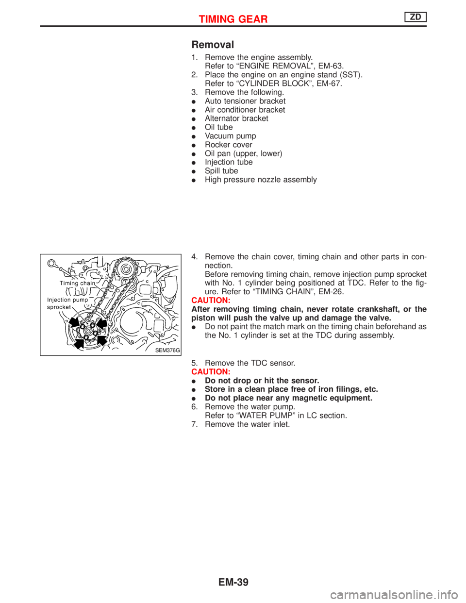
4. Remove the chain cover, timing chain and other parts in con-
nection.
Before removing timing chain, remove injection pump sprocket
with No. 1 cylinder being positioned at TDC. Refer to the fig-
ure. Refer to ªTIMING CHAINº, EM-26.
CAUTION:
After removing timing chain, never rotate crankshaft, or the
piston will push the valve up and damage the valve.
IDo not paint the match mark on the timing chain beforehand as
the No. 1 cylinder is set at the TDC during assembly.
5. Remove the TDC sensor.
CAUTION:
IDo not drop or hit the sensor.
IStore in a clean place free of iron filings, etc.
IDo not place near any magnetic equipment.
6. Remove the water pump.
Refer to ªWATER PUMPº in LC section.
7. Remove the water inlet.
SEM376G
TIMING GEARZD
EM-39
Page 1149 of 1767
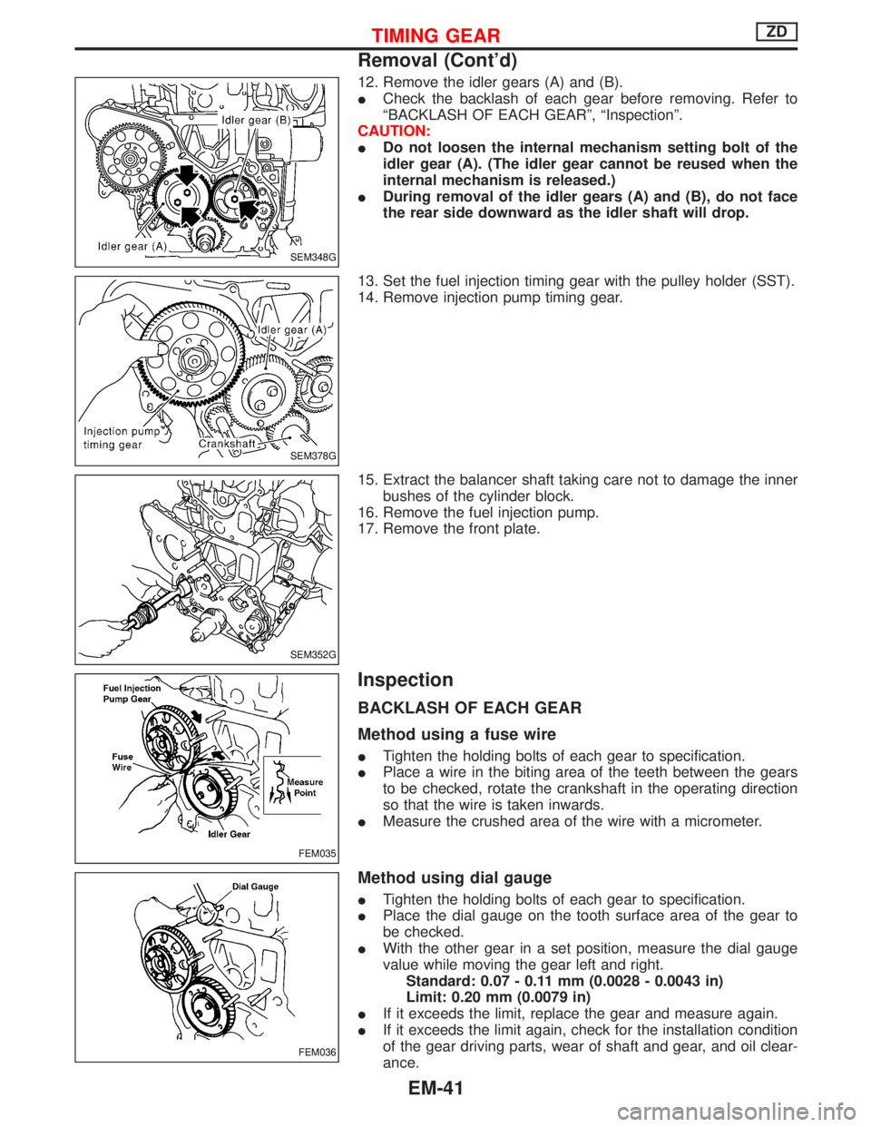
12. Remove the idler gears (A) and (B).
ICheck the backlash of each gear before removing. Refer to
ªBACKLASH OF EACH GEARº, ªInspectionº.
CAUTION:
IDo not loosen the internal mechanism setting bolt of the
idler gear (A). (The idler gear cannot be reused when the
internal mechanism is released.)
IDuring removal of the idler gears (A) and (B), do not face
the rear side downward as the idler shaft will drop.
13. Set the fuel injection timing gear with the pulley holder (SST).
14. Remove injection pump timing gear.
15. Extract the balancer shaft taking care not to damage the inner
bushes of the cylinder block.
16. Remove the fuel injection pump.
17. Remove the front plate.
Inspection
BACKLASH OF EACH GEAR
Method using a fuse wire
ITighten the holding bolts of each gear to specification.
IPlace a wire in the biting area of the teeth between the gears
to be checked, rotate the crankshaft in the operating direction
so that the wire is taken inwards.
IMeasure the crushed area of the wire with a micrometer.
Method using dial gauge
ITighten the holding bolts of each gear to specification.
IPlace the dial gauge on the tooth surface area of the gear to
be checked.
IWith the other gear in a set position, measure the dial gauge
value while moving the gear left and right.
Standard: 0.07 - 0.11 mm (0.0028 - 0.0043 in)
Limit: 0.20 mm (0.0079 in)
IIf it exceeds the limit, replace the gear and measure again.
IIf it exceeds the limit again, check for the installation condition
of the gear driving parts, wear of shaft and gear, and oil clear-
ance.
SEM348G
SEM378G
SEM352G
FEM035
FEM036
TIMING GEARZD
Removal (Cont'd)
EM-41
Page 1154 of 1767
Installation
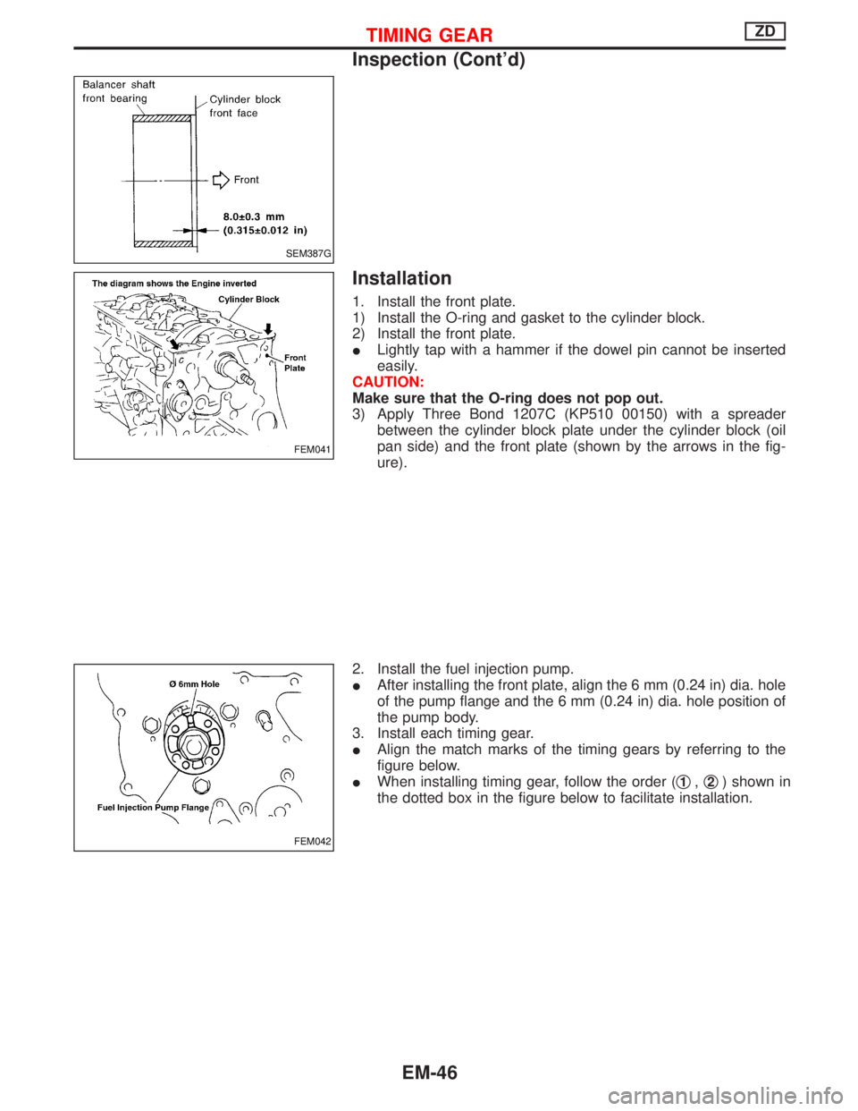
1. Install the front plate.
1) Install the O-ring and gasket to the cylinder block.
2) Install the front plate.
ILightly tap with a hammer if the dowel pin cannot be inserted
easily.
CAUTION:
Make sure that the O-ring does not pop out.
3) Apply Three Bond 1207C (KP510 00150) with a spreader
between the cylinder block plate under the cylinder block (oil
pan side) and the front plate (shown by the arrows in the fig-
ure).
2. Install the fuel injection pump.
IAfter installing the front plate, align the 6 mm (0.24 in) dia. hole
of the pump flange and the 6 mm (0.24 in) dia. hole position of
the pump body.
3. Install each timing gear.
IAlign the match marks of the timing gears by referring to the
figure below.
IWhen installing timing gear, follow the order (q
1,q2) shown in
the dotted box in the figure below to facilitate installation.
SEM387G
FEM041
FEM042
TIMING GEARZD
Inspection (Cont'd)
EM-46
Page 1160 of 1767
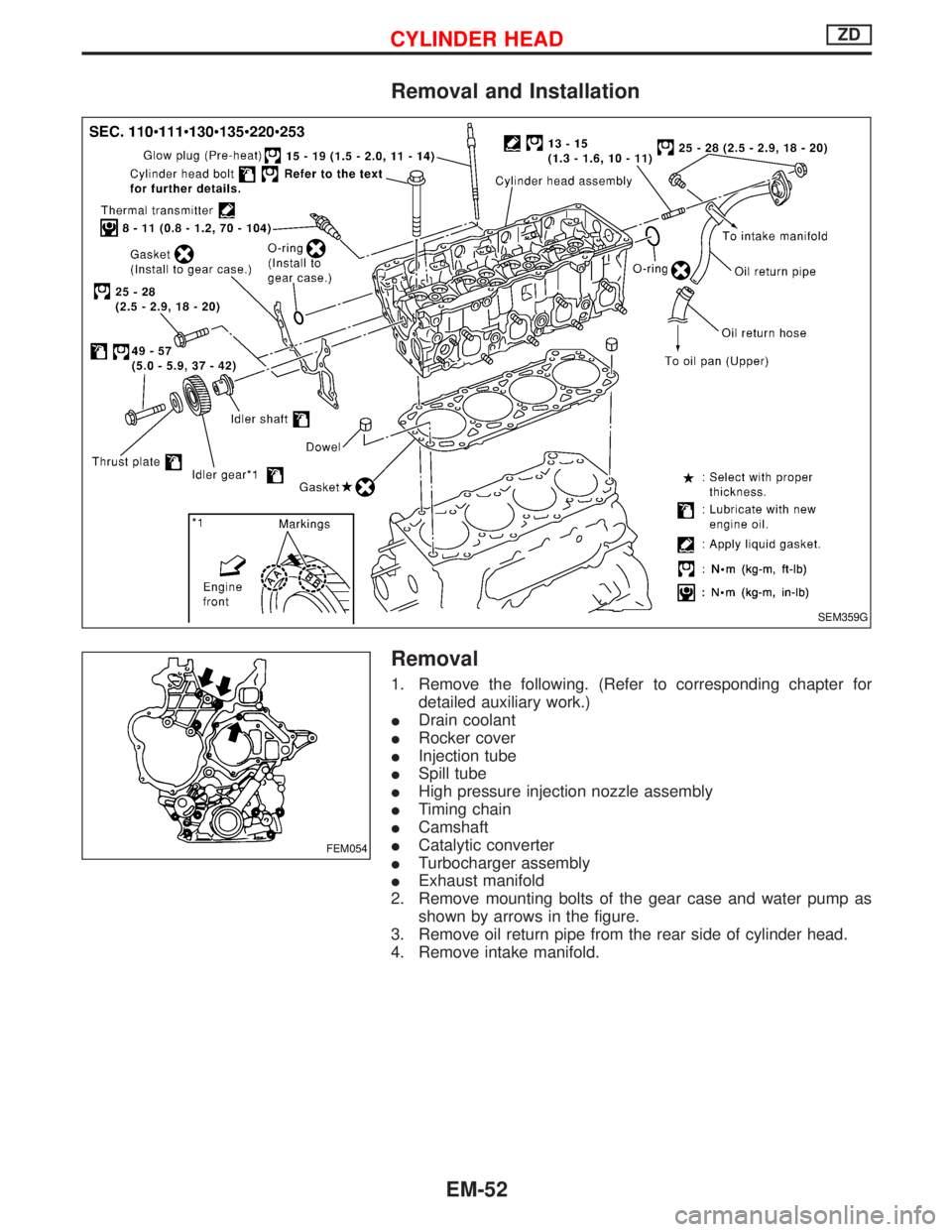
Removal and Installation
Removal
1. Remove the following. (Refer to corresponding chapter for
detailed auxiliary work.)
IDrain coolant
IRocker cover
IInjection tube
ISpill tube
IHigh pressure injection nozzle assembly
ITiming chain
ICamshaft
ICatalytic converter
ITurbocharger assembly
IExhaust manifold
2. Remove mounting bolts of the gear case and water pump as
shown by arrows in the figure.
3. Remove oil return pipe from the rear side of cylinder head.
4. Remove intake manifold.
SEM359G
FEM054
CYLINDER HEADZD
EM-52
Page 1176 of 1767
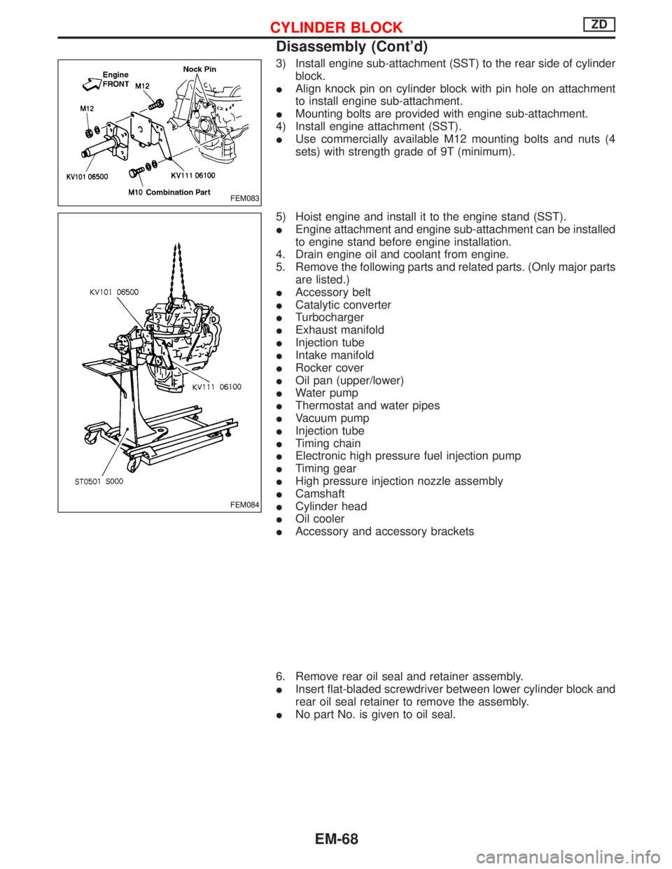
3) Install engine sub-attachment (SST) to the rear side of cylinder
block.
IAlign knock pin on cylinder block with pin hole on attachment
to install engine sub-attachment.
IMounting bolts are provided with engine sub-attachment.
4) Install engine attachment (SST).
IUse commercially available M12 mounting bolts and nuts (4
sets) with strength grade of 9T (minimum).
5) Hoist engine and install it to the engine stand (SST).
IEngine attachment and engine sub-attachment can be installed
to engine stand before engine installation.
4. Drain engine oil and coolant from engine.
5. Remove the following parts and related parts. (Only major parts
are listed.)
IAccessory belt
ICatalytic converter
ITurbocharger
IExhaust manifold
IInjection tube
IIntake manifold
IRocker cover
IOil pan (upper/lower)
IWater pump
IThermostat and water pipes
IVacuum pump
IInjection tube
ITiming chain
IElectronic high pressure fuel injection pump
ITiming gear
IHigh pressure injection nozzle assembly
ICamshaft
ICylinder head
IOil cooler
IAccessory and accessory brackets
6. Remove rear oil seal and retainer assembly.
IInsert flat-bladed screwdriver between lower cylinder block and
rear oil seal retainer to remove the assembly.
INo part No. is given to oil seal.
FEM083
FEM084
CYLINDER BLOCKZD
Disassembly (Cont'd)
EM-68
Page 1206 of 1767
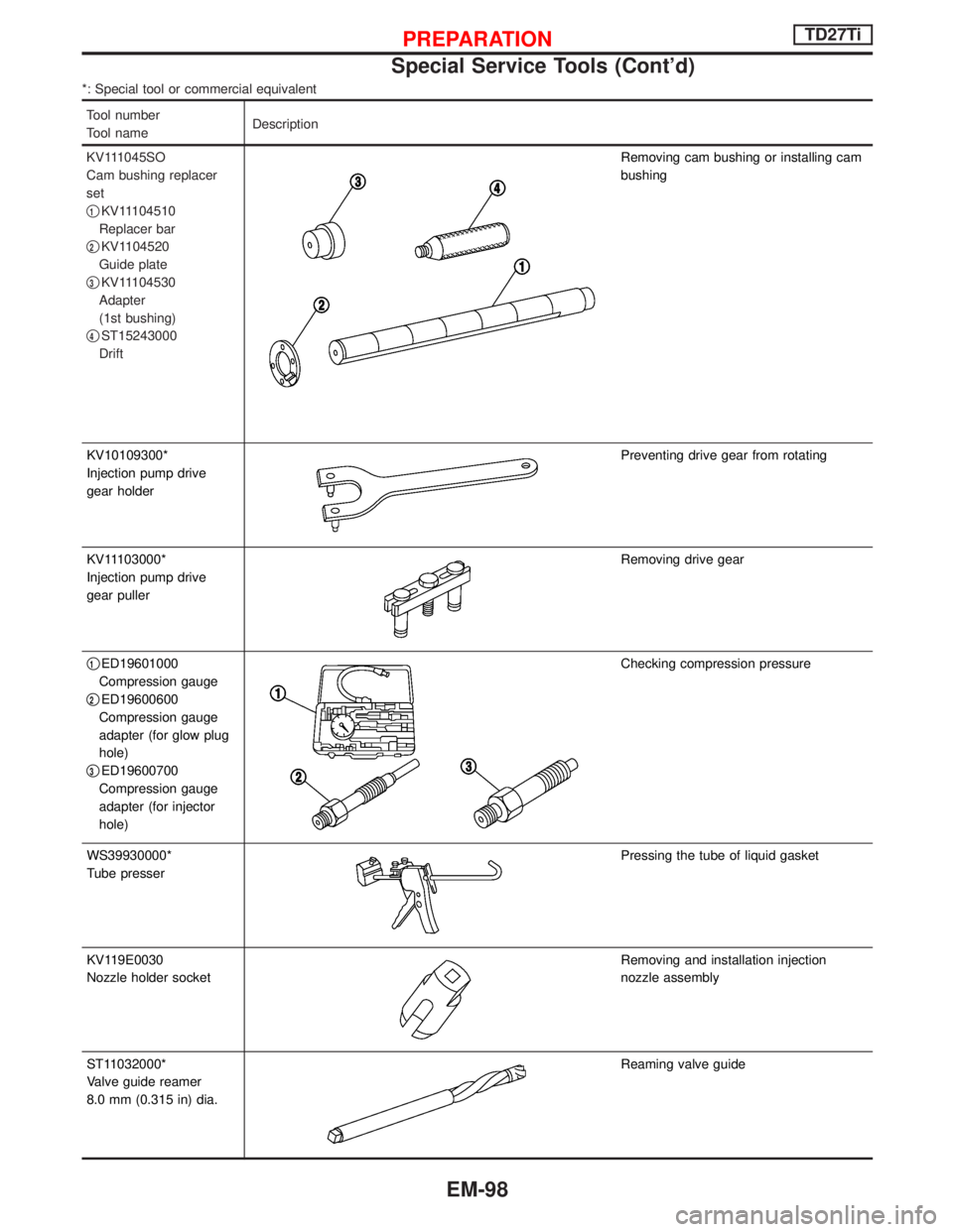
*: Special tool or commercial equivalent
Tool number
Tool nameDescription
KV111045SO
Cam bushing replacer
set
q
1KV11104510
Replacer bar
q
2KV1104520
Guide plate
q
3KV11104530
Adapter
(1st bushing)
q
4ST15243000
Drift
Removing cam bushing or installing cam
bushing
KV10109300*
Injection pump drive
gear holder
Preventing drive gear from rotating
KV11103000*
Injection pump drive
gear puller
Removing drive gear
q
1ED19601000
Compression gauge
q
2ED19600600
Compression gauge
adapter (for glow plug
hole)
q
3ED19600700
Compression gauge
adapter (for injector
hole)
Checking compression pressure
WS39930000*
Tube presser
Pressing the tube of liquid gasket
KV119E0030
Nozzle holder socket
Removing and installation injection
nozzle assembly
ST11032000*
Valve guide reamer
8.0 mm (0.315 in) dia.
Reaming valve guide
PREPARATIONTD27Ti
Special Service Tools (Cont'd)
EM-98