2002 NISSAN TERRANO Injection pump
[x] Cancel search: Injection pumpPage 774 of 1767
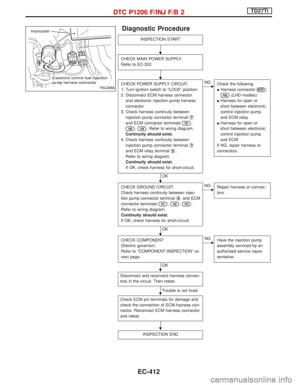
Diagnostic Procedure
INSPECTION START
CHECK MAIN POWER SUPPLY.
Refer to EC-352.
CHECK POWER SUPPLY CIRCUIT.
1. Turn ignition switch to ªLOCKº position.
2. Disconnect ECM harness connector
and electronic injection pump harness
connector.
3. Check harness continuity between
injection pump connector terminalq
7
and ECM connector terminals107,
108,109. Refer to wiring diagram.
Continuity should exist.
4. Check harness continuity between
injection pump connector terminalq
7
and ECM relay terminalq5.
Refer to wiring diagram.
Continuity should exist.
If OK, check harness for short-circuit.
OK
ENG
Check the following.
IHarness connector
M787,
F66(LHD models)
IHarness for open or
short between electronic
control injection pump
and ECM relay
IHarness for open or
short between electronic
control injection pump
and ECM
If NG, repair harness or
connectors.
CHECK GROUND CIRCUIT.
Check harness continuity between injec-
tion pump connector terminalq
4and ECM
connector terminals
101,102,103.
Refer to wiring diagram.
Continuity should exist.
If OK, check harness for short-circuit.
OK
ENG
Repair harness or connec-
tors.
CHECK COMPONENT
(Electric governor).
Refer to ªCOMPONENT INSPECTIONº on
next page.
OK
ENG
Have the injection pump
assembly serviced by an
authorised service repre-
sentative.
Disconnect and reconnect harness connec-
tors in the circuit. Then retest.
Trouble is not fixed.
Check ECM pin terminals for damage and
check the connection of ECM harness con-
nector. Reconnect ECM harness connector
and retest.
INSPECTION END
YEC248A
H
H
H
H
H
H
H
DTC P1206 F/INJ F/B 2TD27Ti
EC-412
Page 775 of 1767
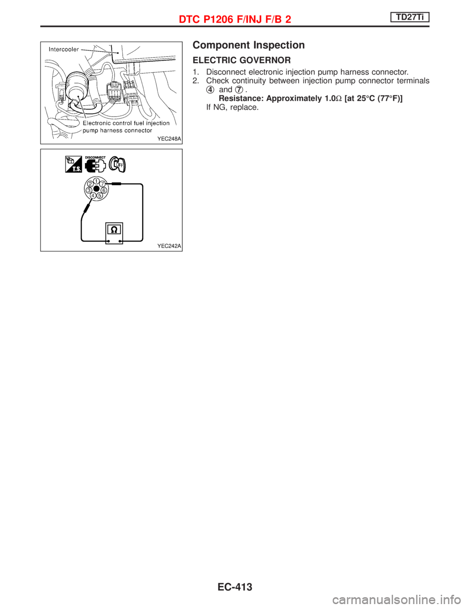
Component Inspection
ELECTRIC GOVERNOR
1. Disconnect electronic injection pump harness connector.
2. Check continuity between injection pump connector terminals
q
4andq7.
Resistance: Approximately 1.0W[at 25ÉC (77ÉF)]
If NG, replace.
YEC248A
YEC242A
DTC P1206 F/INJ F/B 2TD27Ti
EC-413
Page 778 of 1767
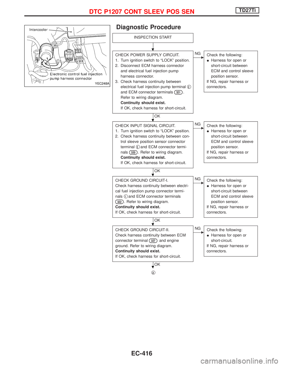
Diagnostic Procedure
INSPECTION START
CHECK POWER SUPPLY CIRCUIT.
1. Turn ignition switch to ªLOCKº position.
2. Disconnect ECM harness connector
and electrical fuel injection pump
harness connector.
3. Check harness continuity between
electrical fuel injection pump terminalq
2
and ECM connector terminals321.
Refer to wiring diagram.
Continuity should exist.
If OK, check harness for short-circuit.
OK
ENG
Check the following:
IHarness for open or
short-circuit between
ECM and control sleeve
position sensor.
If NG, repair harness or
connectors.
CHECK INPUT SIGNAL CIRCUIT.
1. Turn ignition switch to ªLOCKº position.
2. Check harness continuity between con-
trol sleeve position sensor connector
terminalq
3and ECM connector termi-
nals
320. Refer to wiring diagram.
Continuity should exist.
If OK, check harness for short-circuit.
OK
ENG
Check the following:
IHarness for open or
short-circuit between
ECM and control sleeve
position sensor.
If NG, repair harness or
connectors.
CHECK GROUND CIRCUIT-I.
Check harness continuity between electri-
cal fuel injection pump connector termi-
nalsq
1and ECM connector terminals
322. Refer to wiring diagram.
Continuity should exist.
If OK, check harness for short-circuit.
OK
ENG
Check the following:
IHarness for open or
short-circuit between
ECM and control sleeve
position sensor.
If NG, repair harness or
connectors.
CHECK GROUND CIRCUIT-II.
Check harness continuity between ECM
connector terminal
327and engine
ground. Refer to wiring diagram.
Continuity should exist.
If OK, check harness for short-circuit.
OK
ENG
Check the following:
IHarness for open or
short-circuit.
If NG, repair harness or
connectors.
qA
YEC248A
H
H
H
H
H
DTC P1207 CONT SLEEV POS SENTD27Ti
EC-416
Page 779 of 1767
qA
CHECK COMPONENT
(Control sleeve position sensor).
Refer to ªCOMPONENT INSPECTIONº on
page EC-417.
OK
ENG
Have the injection pump
assembly serviced by an
authorised service repre-
sentative.
Disconnect and reconnect harness con-
nectors in the circuit. Then retest.
Trouble is not fixed.
Check ECM pin terminals for damage and
check the connection of ECM harness
connector. Reconnect ECM harness con-
nector and retest.
INSPECTION END
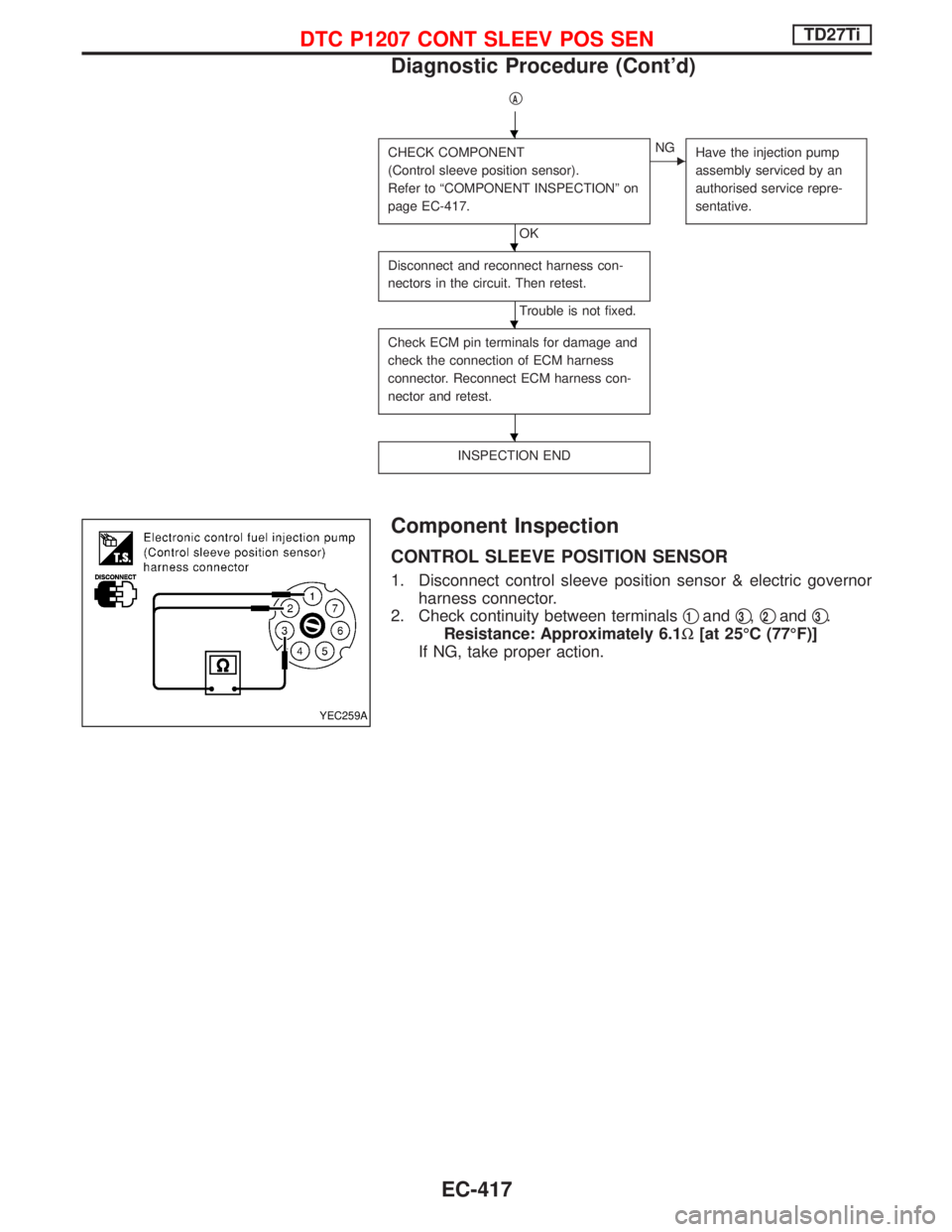
Component Inspection
CONTROL SLEEVE POSITION SENSOR
1. Disconnect control sleeve position sensor & electric governor
harness connector.
2. Check continuity between terminalsq
1andq3,q2andq3.
Resistance: Approximately 6.1W[at 25ÉC (77ÉF)]
If NG, take proper action.
YEC259A
H
H
H
H
DTC P1207 CONT SLEEV POS SENTD27Ti
Diagnostic Procedure (Cont'd)
EC-417
Page 791 of 1767
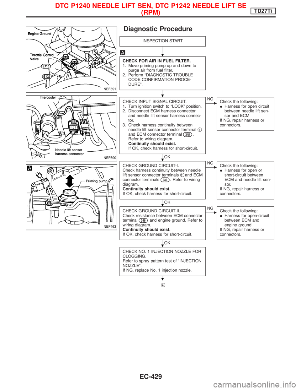
Diagnostic Procedure
INSPECTION START
CHECK FOR AIR IN FUEL FILTER.
1. Move priming pump up and down to
purge air from fuel filter.
2. Perform ªDIAGNOSTIC TROUBLE
CODE CONFIRMATION PROCE-
DUREº.
CHECK INPUT SIGNAL CIRCUIT.
1. Turn ignition switch to ªLOCKº position.
2. Disconnect ECM harness connector
and needle lift sensor harness connec-
tor.
3. Check harness continuity between
needle lift sensor connector terminalq
1and ECM connector terminal345.
Refer to wiring diagram.
Continuity should exist.
If OK, check harness for short-circuit.
OK
ENG
Check the following:
IHarness for open circuit
between needle lift sen-
sor and ECM
If NG, repair harness or
connectors.
CHECK GROUND CIRCUIT-I.
Check harness continuity between needle
lift sensor connector terminalsq
2and ECM
connector terminals333. Refer to wiring
diagram.
Continuity should exist.
If OK, check harness for short-circuit.
OK
ENG
Check the following:
IHarness for open or
short-circuit between
ECM and needle lift sen-
sor.
If NG, repair harness or
connectors.
CHECK GROUND CIRCUIT-II.
Check resistance between ECM connector
terminal
346and engine ground. Refer to
wiring diagram.
Continuity should exist.
If OK, check harness for short-circuit.
OK
ENG
Check the following:
IHarness for open-circuit
between ECM and
engine ground
If NG, repair harness or
connectors.
CHECK NO. 1 INJECTION NOZZLE FOR
CLOGGING.
Refer to spray pattern test of ªINJECTION
NOZZLEº.
If NG, replace No. 1 injection nozzle.
qA
NEF591
NEF690
NEF463
H
H
H
H
H
H
DTC P1240 NEEDLE LIFT SEN, DTC P1242 NEEDLE LIFT SE
(RPM)TD27Ti
EC-429
Page 815 of 1767
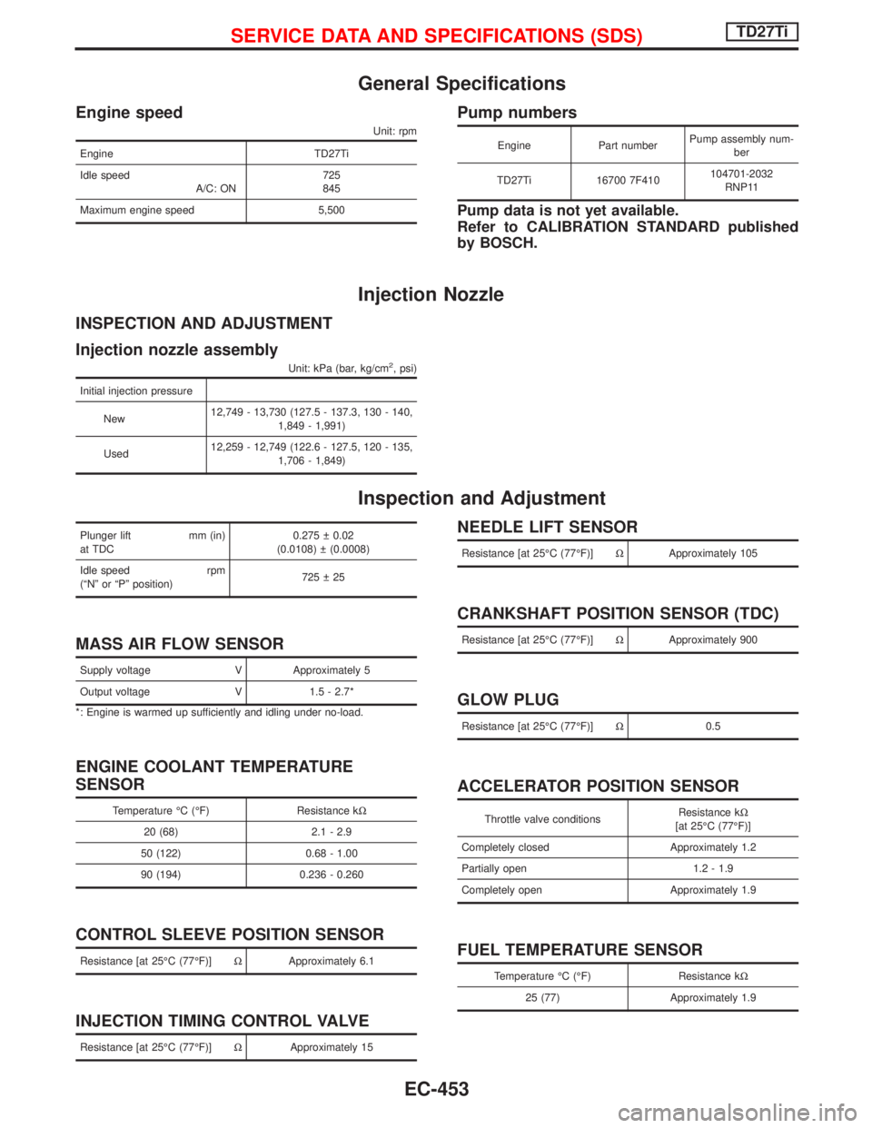
General Specifications
Engine speed
Unit: rpm
Engine TD27Ti
Idle speed
A/C: ON725
845
Maximum engine speed 5,500
Pump numbers
Engine Part numberPump assembly num-
ber
TD27Ti 16700 7F410104701-2032
RNP11
Pump data is not yet available.
Refer to CALIBRATION STANDARD published
by BOSCH.
Injection Nozzle
INSPECTION AND ADJUSTMENT
Injection nozzle assembly
Unit: kPa (bar, kg/cm2, psi)
Initial injection pressure
New12,749 - 13,730 (127.5 - 137.3, 130 - 140,
1,849 - 1,991)
Used12,259 - 12,749 (122.6 - 127.5, 120 - 135,
1,706 - 1,849)
Inspection and Adjustment
Plunger lift mm (in)
at TDC0.275 0.02
(0.0108) (0.0008)
Idle speed rpm
(ªNº or ªPº position)725 25
MASS AIR FLOW SENSOR
Supply voltage V Approximately 5
Output voltage V 1.5 - 2.7*
*: Engine is warmed up sufficiently and idling under no-load.
ENGINE COOLANT TEMPERATURE
SENSOR
Temperature ÉC (ÉF) Resistance kW
20 (68) 2.1 - 2.9
50 (122) 0.68 - 1.00
90 (194) 0.236 - 0.260
CONTROL SLEEVE POSITION SENSOR
Resistance [at 25ÉC (77ÉF)]WApproximately 6.1
INJECTION TIMING CONTROL VALVE
Resistance [at 25ÉC (77ÉF)]WApproximately 15
NEEDLE LIFT SENSOR
Resistance [at 25ÉC (77ÉF)]WApproximately 105
CRANKSHAFT POSITION SENSOR (TDC)
Resistance [at 25ÉC (77ÉF)]WApproximately 900
GLOW PLUG
Resistance [at 25ÉC (77ÉF)]W0.5
ACCELERATOR POSITION SENSOR
Throttle valve conditionsResistance kW
[at 25ÉC (77ÉF)]
Completely closed Approximately 1.2
Partially open 1.2 - 1.9
Completely open Approximately 1.9
FUEL TEMPERATURE SENSOR
Temperature ÉC (ÉF) Resistance kW
25 (77) Approximately 1.9
SERVICE DATA AND SPECIFICATIONS (SDS)TD27Ti
EC-453
Page 837 of 1767
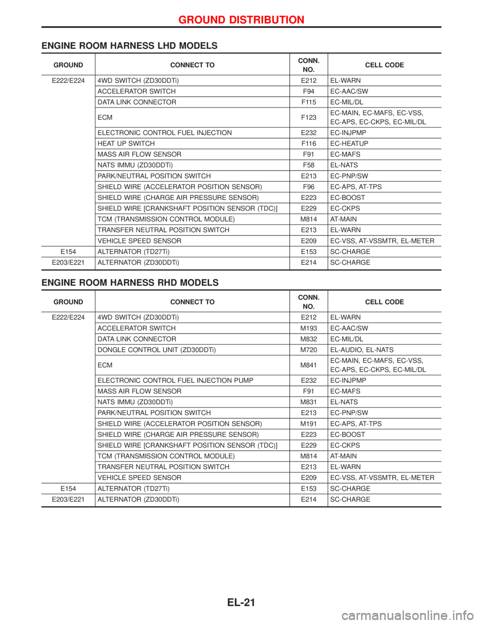
ENGINE ROOM HARNESS LHD MODELS
GROUND CONNECT TOCONN.
NO.CELL CODE
E222/E224 4WD SWITCH (ZD30DDTi) E212 EL-WARN
ACCELERATOR SWITCH F94 EC-AAC/SW
DATA LINK CONNECTOR F115 EC-MIL/DL
ECM F123EC-MAIN, EC-MAFS, EC-VSS,
EC-APS, EC-CKPS, EC-MIL/DL
ELECTRONIC CONTROL FUEL INJECTION E232 EC-INJPMP
HEAT UP SWITCH F116 EC-HEATUP
MASS AIR FLOW SENSOR F91 EC-MAFS
NATS IMMU (ZD30DDTi) F58 EL-NATS
PARK/NEUTRAL POSITION SWITCH E213 EC-PNP/SW
SHIELD WIRE (ACCELERATOR POSITION SENSOR) F96 EC-APS, AT-TPS
SHIELD WIRE (CHARGE AIR PRESSURE SENSOR) E223 EC-BOOST
SHIELD WIRE [CRANKSHAFT POSITION SENSOR (TDC)] E229 EC-CKPS
TCM (TRANSMISSION CONTROL MODULE) M814 AT-MAIN
TRANSFER NEUTRAL POSITION SWITCH E213 EL-WARN
VEHICLE SPEED SENSOR E209 EC-VSS, AT-VSSMTR, EL-METER
E154 ALTERNATOR (TD27Ti) E153 SC-CHARGE
E203/E221 ALTERNATOR (ZD30DDTi) E214 SC-CHARGE
ENGINE ROOM HARNESS RHD MODELS
GROUND CONNECT TOCONN.
NO.CELL CODE
E222/E224 4WD SWITCH (ZD30DDTi) E212 EL-WARN
ACCELERATOR SWITCH M193 EC-AAC/SW
DATA LINK CONNECTOR M832 EC-MIL/DL
DONGLE CONTROL UNIT (ZD30DDTi) M720 EL-AUDIO, EL-NATS
ECM M841EC-MAIN, EC-MAFS, EC-VSS,
EC-APS, EC-CKPS, EC-MIL/DL
ELECTRONIC CONTROL FUEL INJECTION PUMP E232 EC-INJPMP
MASS AIR FLOW SENSOR F91 EC-MAFS
NATS IMMU (ZD30DDTi) M831 EL-NATS
PARK/NEUTRAL POSITION SWITCH E213 EC-PNP/SW
SHIELD WIRE (ACCELERATOR POSITION SENSOR) M191 EC-APS, AT-TPS
SHIELD WIRE (CHARGE AIR PRESSURE SENSOR) E223 EC-BOOST
SHIELD WIRE [CRANKSHAFT POSITION SENSOR (TDC)] E229 EC-CKPS
TCM (TRANSMISSION CONTROL MODULE) M814 AT-MAIN
TRANSFER NEUTRAL POSITION SWITCH E213 EL-WARN
VEHICLE SPEED SENSOR E209 EC-VSS, AT-VSSMTR, EL-METER
E154 ALTERNATOR (TD27Ti) E153 SC-CHARGE
E203/E221 ALTERNATOR (ZD30DDTi) E214 SC-CHARGE
GROUND DISTRIBUTION
EL-21
Page 1107 of 1767
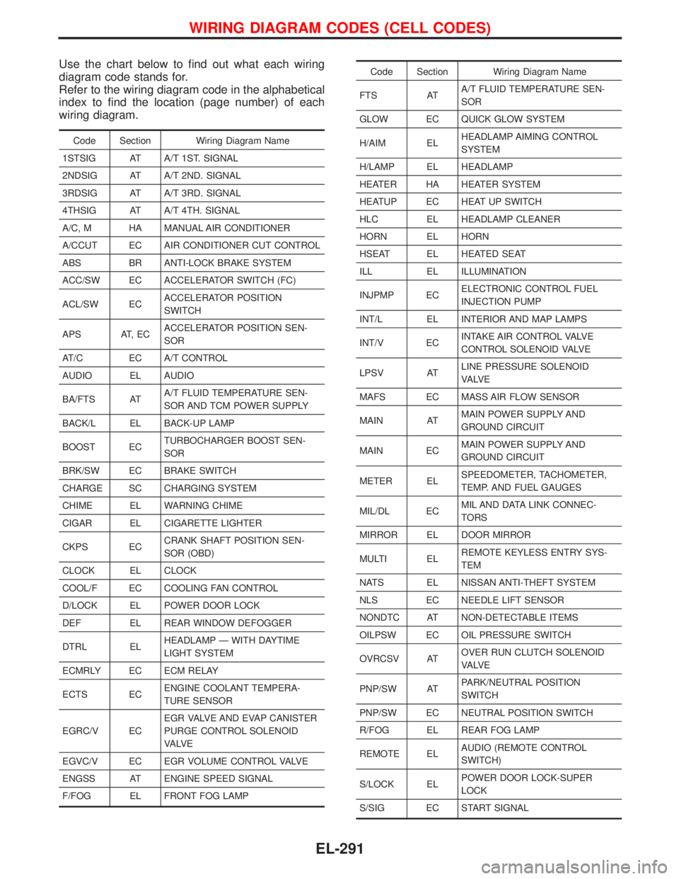
Use the chart below to find out what each wiring
diagram code stands for.
Refer to the wiring diagram code in the alphabetical
index to find the location (page number) of each
wiring diagram.
Code Section Wiring Diagram Name
1STSIG AT A/T 1ST. SIGNAL
2NDSIG AT A/T 2ND. SIGNAL
3RDSIG AT A/T 3RD. SIGNAL
4THSIG AT A/T 4TH. SIGNAL
A/C, M HA MANUAL AIR CONDITIONER
A/CCUT EC AIR CONDITIONER CUT CONTROL
ABS BR ANTI-LOCK BRAKE SYSTEM
ACC/SW EC ACCELERATOR SWITCH (FC)
ACL/SW ECACCELERATOR POSITION
SWITCH
APS AT, ECACCELERATOR POSITION SEN-
SOR
AT/C EC A/T CONTROL
AUDIO EL AUDIO
BA/FTS ATA/T FLUID TEMPERATURE SEN-
SOR AND TCM POWER SUPPLY
BACK/L EL BACK-UP LAMP
BOOST ECTURBOCHARGER BOOST SEN-
SOR
BRK/SW EC BRAKE SWITCH
CHARGE SC CHARGING SYSTEM
CHIME EL WARNING CHIME
CIGAR EL CIGARETTE LIGHTER
CKPS ECCRANK SHAFT POSITION SEN-
SOR (OBD)
CLOCK EL CLOCK
COOL/F EC COOLING FAN CONTROL
D/LOCK EL POWER DOOR LOCK
DEF EL REAR WINDOW DEFOGGER
DTRL ELHEADLAMP Ð WITH DAYTIME
LIGHT SYSTEM
ECMRLY EC ECM RELAY
ECTS ECENGINE COOLANT TEMPERA-
TURE SENSOR
EGRC/V ECEGR VALVE AND EVAP CANISTER
PURGE CONTROL SOLENOID
VA LV E
EGVC/V EC EGR VOLUME CONTROL VALVE
ENGSS AT ENGINE SPEED SIGNAL
F/FOG EL FRONT FOG LAMP
Code Section Wiring Diagram Name
FTS ATA/T FLUID TEMPERATURE SEN-
SOR
GLOW EC QUICK GLOW SYSTEM
H/AIM ELHEADLAMP AIMING CONTROL
SYSTEM
H/LAMP EL HEADLAMP
HEATER HA HEATER SYSTEM
HEATUP EC HEAT UP SWITCH
HLC EL HEADLAMP CLEANER
HORN EL HORN
HSEAT EL HEATED SEAT
ILL EL ILLUMINATION
INJPMP ECELECTRONIC CONTROL FUEL
INJECTION PUMP
INT/L EL INTERIOR AND MAP LAMPS
INT/V ECINTAKE AIR CONTROL VALVE
CONTROL SOLENOID VALVE
LPSV ATLINE PRESSURE SOLENOID
VA LV E
MAFS EC MASS AIR FLOW SENSOR
MAIN ATMAIN POWER SUPPLY AND
GROUND CIRCUIT
MAIN ECMAIN POWER SUPPLY AND
GROUND CIRCUIT
METER ELSPEEDOMETER, TACHOMETER,
TEMP. AND FUEL GAUGES
MIL/DL ECMIL AND DATA LINK CONNEC-
TORS
MIRROR EL DOOR MIRROR
MULTI ELREMOTE KEYLESS ENTRY SYS-
TEM
NATS EL NISSAN ANTI-THEFT SYSTEM
NLS EC NEEDLE LIFT SENSOR
NONDTC AT NON-DETECTABLE ITEMS
OILPSW EC OIL PRESSURE SWITCH
OVRCSV ATOVER RUN CLUTCH SOLENOID
VA LV E
PNP/SW ATPARK/NEUTRAL POSITION
SWITCH
PNP/SW EC NEUTRAL POSITION SWITCH
R/FOG EL REAR FOG LAMP
REMOTE ELAUDIO (REMOTE CONTROL
SWITCH)
S/LOCK ELPOWER DOOR LOCK-SUPER
LOCK
S/SIG EC START SIGNAL
WIRING DIAGRAM CODES (CELL CODES)
EL-291