2002 NISSAN TERRANO general
[x] Cancel search: generalPage 438 of 1767
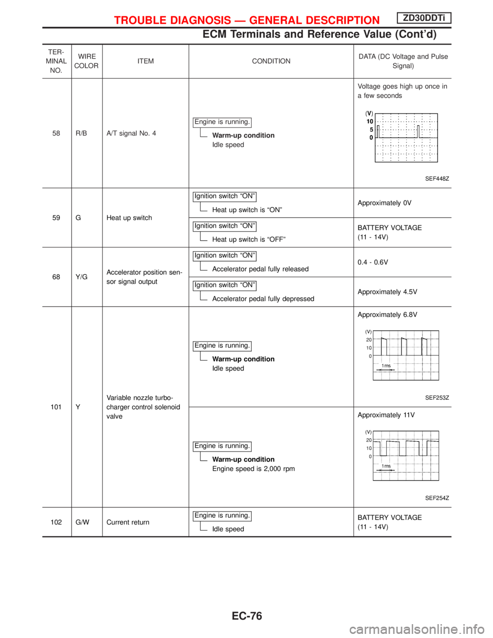
TER-
MINAL
NO.WIRE
COLORITEM CONDITIONDATA (DC Voltage and Pulse
Signal)
58 R/B A/T signal No. 4Engine is running.
Warm-up condition
Idle speedVoltage goes high up once in
a few seconds
SEF448Z
59 G Heat up switchIgnition switch ªONºHeat up switch is ªONºApproximately 0V
Ignition switch ªONº
Heat up switch is ªOFFºBATTERY VOLTAGE
(11 - 14V)
68 Y/GAccelerator position sen-
sor signal outputIgnition switch ªONº
Accelerator pedal fully released0.4 - 0.6V
Ignition switch ªONº
Accelerator pedal fully depressedApproximately 4.5V
101 YVariable nozzle turbo-
charger control solenoid
valveEngine is running.
Warm-up condition
Idle speedApproximately 6.8V
SEF253Z
Engine is running.
Warm-up condition
Engine speed is 2,000 rpmApproximately 11V
SEF254Z
102 G/W Current returnEngine is running.Idle speedBATTERY VOLTAGE
(11 - 14V)
TROUBLE DIAGNOSIS Ð GENERAL DESCRIPTIONZD30DDTi
ECM Terminals and Reference Value (Cont'd)
EC-76
Page 439 of 1767
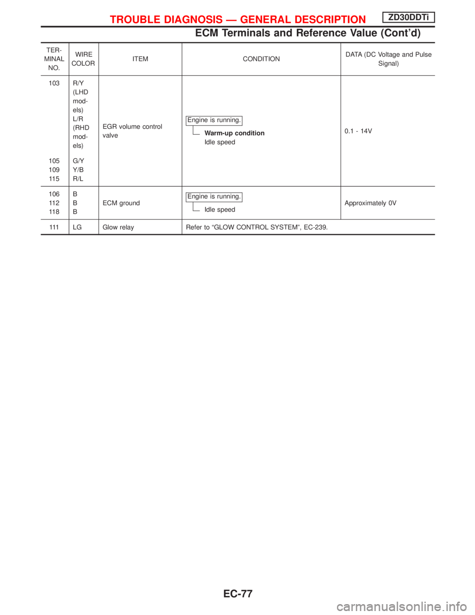
TER-
MINAL
NO.WIRE
COLORITEM CONDITIONDATA (DC Voltage and Pulse
Signal)
103 R/Y
(LHD
mod-
els)
L/R
(RHD
mod-
els)EGR volume control
valveEngine is running.
Warm-up condition
Idle speed0.1 - 14V
105
109
11 5G/Y
Y/B
R/L
106
11 2
11 8B
B
BECM groundEngine is running.
Idle speedApproximately 0V
111 LG Glow relay Refer to ªGLOW CONTROL SYSTEMº, EC-239.
TROUBLE DIAGNOSIS Ð GENERAL DESCRIPTIONZD30DDTi
ECM Terminals and Reference Value (Cont'd)
EC-77
Page 654 of 1767
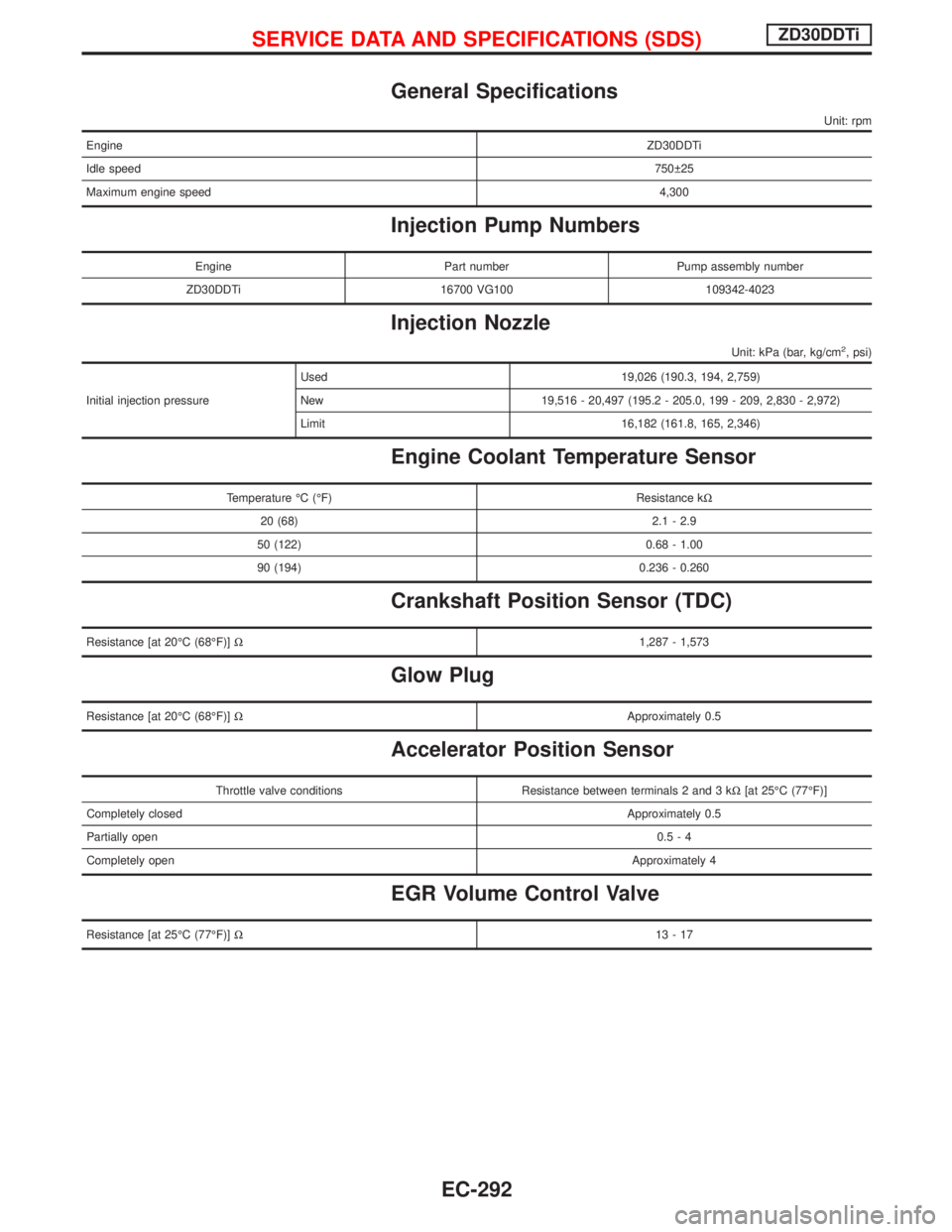
General Specifications
Unit: rpm
EngineZD30DDTi
Idle speed750 25
Maximum engine speed4,300
Injection Pump Numbers
Engine Part number Pump assembly number
ZD30DDTi 16700 VG100 109342-4023
Injection Nozzle
Unit: kPa (bar, kg/cm2, psi)
Initial injection pressureUsed 19,026 (190.3, 194, 2,759)
New 19,516 - 20,497 (195.2 - 205.0, 199 - 209, 2,830 - 2,972)
Limit 16,182 (161.8, 165, 2,346)
Engine Coolant Temperature Sensor
Temperature ÉC (ÉF) Resistance kW
20 (68) 2.1 - 2.9
50 (122) 0.68 - 1.00
90 (194) 0.236 - 0.260
Crankshaft Position Sensor (TDC)
Resistance [at 20ÉC (68ÉF)]W1,287 - 1,573
Glow Plug
Resistance [at 20ÉC (68ÉF)]WApproximately 0.5
Accelerator Position Sensor
Throttle valve conditions Resistance between terminals 2 and 3 kW[at 25ÉC (77ÉF)]
Completely closedApproximately 0.5
Partially open0.5-4
Completely openApproximately 4
EGR Volume Control Valve
Resistance [at 25ÉC (77ÉF)]W13-17
SERVICE DATA AND SPECIFICATIONS (SDS)ZD30DDTi
EC-292
Page 697 of 1767
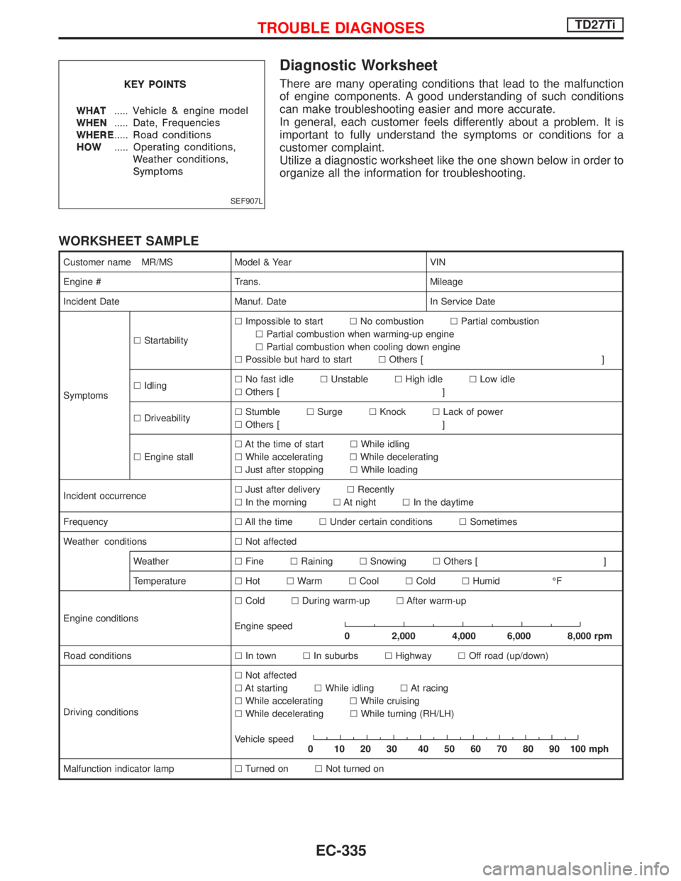
Diagnostic Worksheet
There are many operating conditions that lead to the malfunction
of engine components. A good understanding of such conditions
can make troubleshooting easier and more accurate.
In general, each customer feels differently about a problem. It is
important to fully understand the symptoms or conditions for a
customer complaint.
Utilize a diagnostic worksheet like the one shown below in order to
organize all the information for troubleshooting.
WORKSHEET SAMPLE
Customer name MR/MS Model & Year VIN
Engine # Trans. Mileage
Incident Date Manuf. Date In Service Date
SymptomslStartabilitylImpossible to startlNo combustionlPartial combustion
lPartial combustion when warming-up engine
lPartial combustion when cooling down engine
lPossible but hard to startlOthers [ ]
lIdlinglNo fast idlelUnstablelHigh idlelLow idle
lOthers [ ]
lDriveabilitylStumblelSurgelKnocklLack of power
lOthers [ ]
lEngine stalllAt the time of startlWhile idling
lWhile acceleratinglWhile decelerating
lJust after stoppinglWhile loading
Incident occurrencelJust after deliverylRecently
lIn the morninglAt nightlIn the daytime
FrequencylAll the timelUnder certain conditionslSometimes
Weather conditionslNot affected
WeatherlFinelRaininglSnowinglOthers [ ]
TemperaturelHotlWarmlCoollColdlHumid ÉF
Engine conditionslColdlDuring warm-uplAfter warm-up
Engine speed
0 2,000 4,000 6,000 8,000 rpm
Road conditionslIn townlIn suburbslHighwaylOff road (up/down)
Driving conditionslNot affected
lAt startinglWhile idlinglAt racing
lWhile acceleratinglWhile cruising
lWhile deceleratinglWhile turning (RH/LH)
Vehicle speed
0 102030 405060708090100mph
Malfunction indicator lamplTurned onlNot turned on
SEF907L
TROUBLE DIAGNOSESTD27Ti
EC-335
Page 727 of 1767
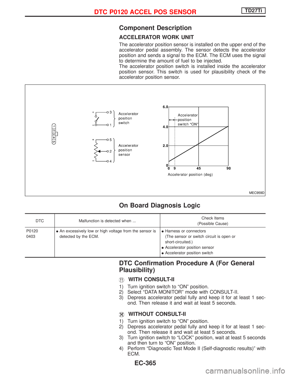
Component Description
ACCELERATOR WORK UNIT
The accelerator position sensor is installed on the upper end of the
accelerator pedal assembly. The sensor detects the accelerator
position and sends a signal to the ECM. The ECM uses the signal
to determine the amount of fuel to be injected.
The accelerator position switch is installed inside the accelerator
position sensor. This switch is used for plausibility check of the
accelerator position sensor.
On Board Diagnosis Logic
DTC Malfunction is detected when ...Check Items
(Possible Cause)
P0120
0403IAn excessively low or high voltage from the sensor is
detected by the ECM.IHarness or connectors
(The sensor or switch circuit is open or
short-circuited.)
IAccelerator position sensor
IAccelerator position switch
DTC Confirmation Procedure A (For General
Plausibility)
WITH CONSULT-II
1) Turn ignition switch to ªONº position.
2) Select ªDATA MONITORº mode with CONSULT-II.
3) Depress accelerator pedal fully and keep it for at least 1 sec-
ond. Then release it and wait at least 5 seconds.
WITHOUT CONSULT-II
1) Turn ignition switch to ªONº position.
2) Depress accelerator pedal fully and keep it for at least 1 sec-
ond. Then release it and wait at least 5 seconds.
3) Turn ignition switch to ªLOCKº position, wait at least 5 seconds
and then turn to ªONº position.
4) Perform ªDiagnostic Test Mode II (Self-diagnostic results)º with
ECM.
MEC959D
DTC P0120 ACCEL POS SENSORTD27Ti
EC-365
Page 815 of 1767
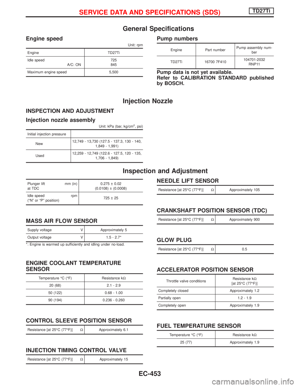
General Specifications
Engine speed
Unit: rpm
Engine TD27Ti
Idle speed
A/C: ON725
845
Maximum engine speed 5,500
Pump numbers
Engine Part numberPump assembly num-
ber
TD27Ti 16700 7F410104701-2032
RNP11
Pump data is not yet available.
Refer to CALIBRATION STANDARD published
by BOSCH.
Injection Nozzle
INSPECTION AND ADJUSTMENT
Injection nozzle assembly
Unit: kPa (bar, kg/cm2, psi)
Initial injection pressure
New12,749 - 13,730 (127.5 - 137.3, 130 - 140,
1,849 - 1,991)
Used12,259 - 12,749 (122.6 - 127.5, 120 - 135,
1,706 - 1,849)
Inspection and Adjustment
Plunger lift mm (in)
at TDC0.275 0.02
(0.0108) (0.0008)
Idle speed rpm
(ªNº or ªPº position)725 25
MASS AIR FLOW SENSOR
Supply voltage V Approximately 5
Output voltage V 1.5 - 2.7*
*: Engine is warmed up sufficiently and idling under no-load.
ENGINE COOLANT TEMPERATURE
SENSOR
Temperature ÉC (ÉF) Resistance kW
20 (68) 2.1 - 2.9
50 (122) 0.68 - 1.00
90 (194) 0.236 - 0.260
CONTROL SLEEVE POSITION SENSOR
Resistance [at 25ÉC (77ÉF)]WApproximately 6.1
INJECTION TIMING CONTROL VALVE
Resistance [at 25ÉC (77ÉF)]WApproximately 15
NEEDLE LIFT SENSOR
Resistance [at 25ÉC (77ÉF)]WApproximately 105
CRANKSHAFT POSITION SENSOR (TDC)
Resistance [at 25ÉC (77ÉF)]WApproximately 900
GLOW PLUG
Resistance [at 25ÉC (77ÉF)]W0.5
ACCELERATOR POSITION SENSOR
Throttle valve conditionsResistance kW
[at 25ÉC (77ÉF)]
Completely closed Approximately 1.2
Partially open 1.2 - 1.9
Completely open Approximately 1.9
FUEL TEMPERATURE SENSOR
Temperature ÉC (ÉF) Resistance kW
25 (77) Approximately 1.9
SERVICE DATA AND SPECIFICATIONS (SDS)TD27Ti
EC-453
Page 1109 of 1767
ENGINE MECHANICAL
SECTION
EM
CONTENTS
ZD
PRECAUTIONS...............................................................3
Parts Requiring Angular Tightening .............................3
Liquid Gasket Application Procedure ..........................3
PREPARATION................................................................4
Special Service Tools ..................................................4
Commercial Service Tools ...........................................6
NOISE, VIBRATION AND HARSHNESS (NVH)
TROUBLESHOOTING.....................................................8
NVH Troubleshooting Chart - Engine Noise ...............9
MEASUREMENT OF COMPRESSION PRESSURE....10
INTERCOOLER............................................................. 11
Removal and Installation ........................................... 11
INTAKE MANIFOLD......................................................12
Removal and Installation ...........................................12
Inspection...................................................................13
CATALYST AND TURBOCHARGER............................14
Removal and Installation ...........................................14
Inspection...................................................................15
EXHAUST MANIFOLD..................................................18
Removal and Installation ...........................................18
Inspection...................................................................19
ROCKER COVER..........................................................20
Removal and Installation ...........................................20
OIL PAN & OIL STRAINER...........................................22
Removal and Installation ...........................................22
VACUUM PUMP............................................................24
Removal and Installation ...........................................24
TIMING CHAIN..............................................................26
Removal and Installation ...........................................26
Removal .....................................................................26
Installation ..................................................................28
CAMSHAFT...................................................................30
Removal and Installation ...........................................30
Removal .....................................................................30
Inspection...................................................................31
Installation ..................................................................33VALVE CLEARANCE INSPECTIONS AND
ADJUSTMENTS.............................................................35
Inspection...................................................................35
Adjustments ...............................................................36
TIMING GEAR...............................................................38
Removal and Installation ...........................................38
Removal .....................................................................39
Inspection...................................................................41
Installation ..................................................................46
OIL SEAL REPLACEMENT..........................................50
CYLINDER HEAD..........................................................52
Removal and Installation ...........................................52
Removal .....................................................................52
Inspection...................................................................53
Installation ..................................................................54
Disassembly...............................................................57
Inspection...................................................................58
Assembly ...................................................................61
ENGINE REMOVAL.......................................................63
Precautions ................................................................63
Removal .....................................................................63
Installation ..................................................................65
Inspection...................................................................65
CYLINDER BLOCK.......................................................66
Selection Procedure for Selective Part
Combination ...............................................................67
Disassembly...............................................................67
Inspection...................................................................71
Assembly ...................................................................80
SERVICE DATA AND SPECIFICATIONS (SDS)..........84
General Specifications ...............................................84
Compression Pressure ..............................................84
Cylinder Head ............................................................84
Valve ..........................................................................84
Valve Seat..................................................................87
Camshaft and Camshaft Bearing ..............................89
Cylinder Block ............................................................90
Piston, Piston Ring and Piston Pin ...........................90
Page 1110 of 1767
Connecting Rod .........................................................91
Crankshaft..................................................................92
Available Main Bearing ..............................................92
Available Connecting Rod Bearing............................93
Miscellaneous Components.......................................94
TD27Ti
PRECAUTIONS.............................................................95
Parts Requiring Angular Tightening ...........................95
Liquid Gasket Application Procedure ........................95
PREPARATION..............................................................96
Special Service Tools ................................................96
Commercial Service Tools .........................................99
ENGINE COMPONENTS - Outer Parts.....................100
ENGINE COMPONENTS - Internal Parts..................102
COMPRESSION PRESSURE......................................103
Measurement of Compression Pressure .................103
CYLINDER HEAD........................................................104Removal ...................................................................105
Disassembly.............................................................106
Inspection.................................................................107
Assembly ................................................................. 113
Installation ................................................................ 114
OIL SEAL REPLACEMENT........................................ 117
TURBOCHARGER....................................................... 119
Removal and Installation ......................................... 119
Inspection................................................................. 119
ENGINE REMOVAL.....................................................123
ENGINE OVERHAUL..................................................125
Disassembly.............................................................125
Inspection.................................................................127
Assembly .................................................................138
SERVICE DATA AND SPECIFICATIONS (SDS)........143
General Specifications .............................................143
Inspection and Adjustment ......................................144
CONTENTS(Cont'd)
EM-2