2002 NISSAN TERRANO general
[x] Cancel search: generalPage 363 of 1767
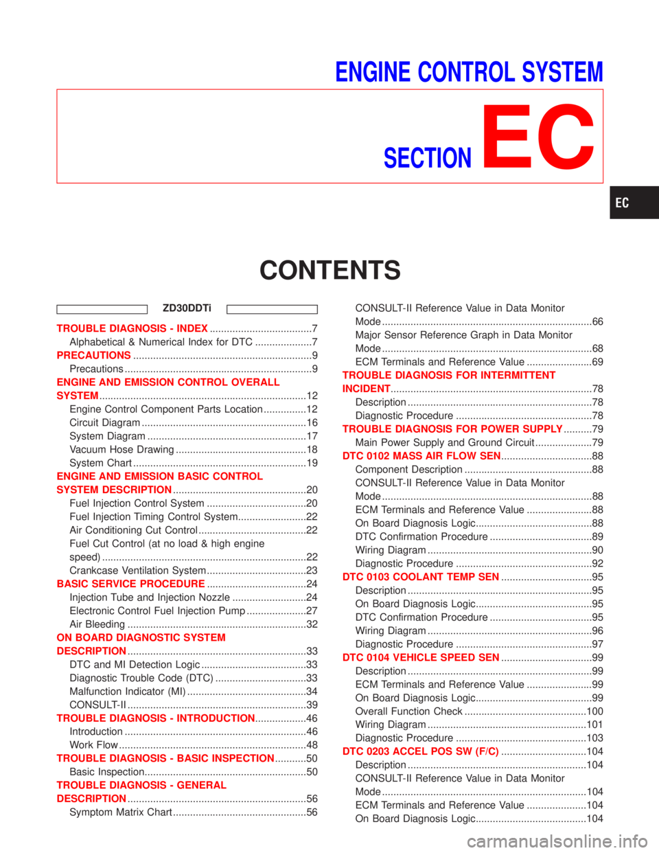
ENGINE CONTROL SYSTEM
SECTION
EC
CONTENTS
ZD30DDTi
TROUBLE DIAGNOSIS - INDEX....................................7
Alphabetical & Numerical Index for DTC ....................7
PRECAUTIONS...............................................................9
Precautions ..................................................................9
ENGINE AND EMISSION CONTROL OVERALL
SYSTEM.........................................................................12
Engine Control Component Parts Location ...............12
Circuit Diagram ..........................................................16
System Diagram ........................................................17
Vacuum Hose Drawing ..............................................18
System Chart .............................................................19
ENGINE AND EMISSION BASIC CONTROL
SYSTEM DESCRIPTION...............................................20
Fuel Injection Control System ...................................20
Fuel Injection Timing Control System........................22
Air Conditioning Cut Control ......................................22
Fuel Cut Control (at no load & high engine
speed) ........................................................................22
Crankcase Ventilation System ...................................23
BASIC SERVICE PROCEDURE...................................24
Injection Tube and Injection Nozzle ..........................24
Electronic Control Fuel Injection Pump .....................27
Air Bleeding ...............................................................32
ON BOARD DIAGNOSTIC SYSTEM
DESCRIPTION...............................................................33
DTC and MI Detection Logic .....................................33
Diagnostic Trouble Code (DTC) ................................33
Malfunction Indicator (MI) ..........................................34
CONSULT-II ...............................................................39
TROUBLE DIAGNOSIS - INTRODUCTION..................46
Introduction ................................................................46
Work Flow ..................................................................48
TROUBLE DIAGNOSIS - BASIC INSPECTION...........50
Basic Inspection.........................................................50
TROUBLE DIAGNOSIS - GENERAL
DESCRIPTION...............................................................56
Symptom Matrix Chart ...............................................56CONSULT-II Reference Value in Data Monitor
Mode ..........................................................................66
Major Sensor Reference Graph in Data Monitor
Mode ..........................................................................68
ECM Terminals and Reference Value .......................69
TROUBLE DIAGNOSIS FOR INTERMITTENT
INCIDENT.......................................................................78
Description .................................................................78
Diagnostic Procedure ................................................78
TROUBLE DIAGNOSIS FOR POWER SUPPLY..........79
Main Power Supply and Ground Circuit ....................79
DTC 0102 MASS AIR FLOW SEN................................88
Component Description .............................................88
CONSULT-II Reference Value in Data Monitor
Mode ..........................................................................88
ECM Terminals and Reference Value .......................88
On Board Diagnosis Logic.........................................88
DTC Confirmation Procedure ....................................89
Wiring Diagram ..........................................................90
Diagnostic Procedure ................................................92
DTC 0103 COOLANT TEMP SEN................................95
Description .................................................................95
On Board Diagnosis Logic.........................................95
DTC Confirmation Procedure ....................................95
Wiring Diagram ..........................................................96
Diagnostic Procedure ................................................97
DTC 0104 VEHICLE SPEED SEN................................99
Description .................................................................99
ECM Terminals and Reference Value .......................99
On Board Diagnosis Logic.........................................99
Overall Function Check ...........................................100
Wiring Diagram ........................................................101
Diagnostic Procedure ..............................................103
DTC 0203 ACCEL POS SW (F/C)..............................104
Description ...............................................................104
CONSULT-II Reference Value in Data Monitor
Mode ........................................................................104
ECM Terminals and Reference Value .....................104
On Board Diagnosis Logic.......................................104
Page 366 of 1767
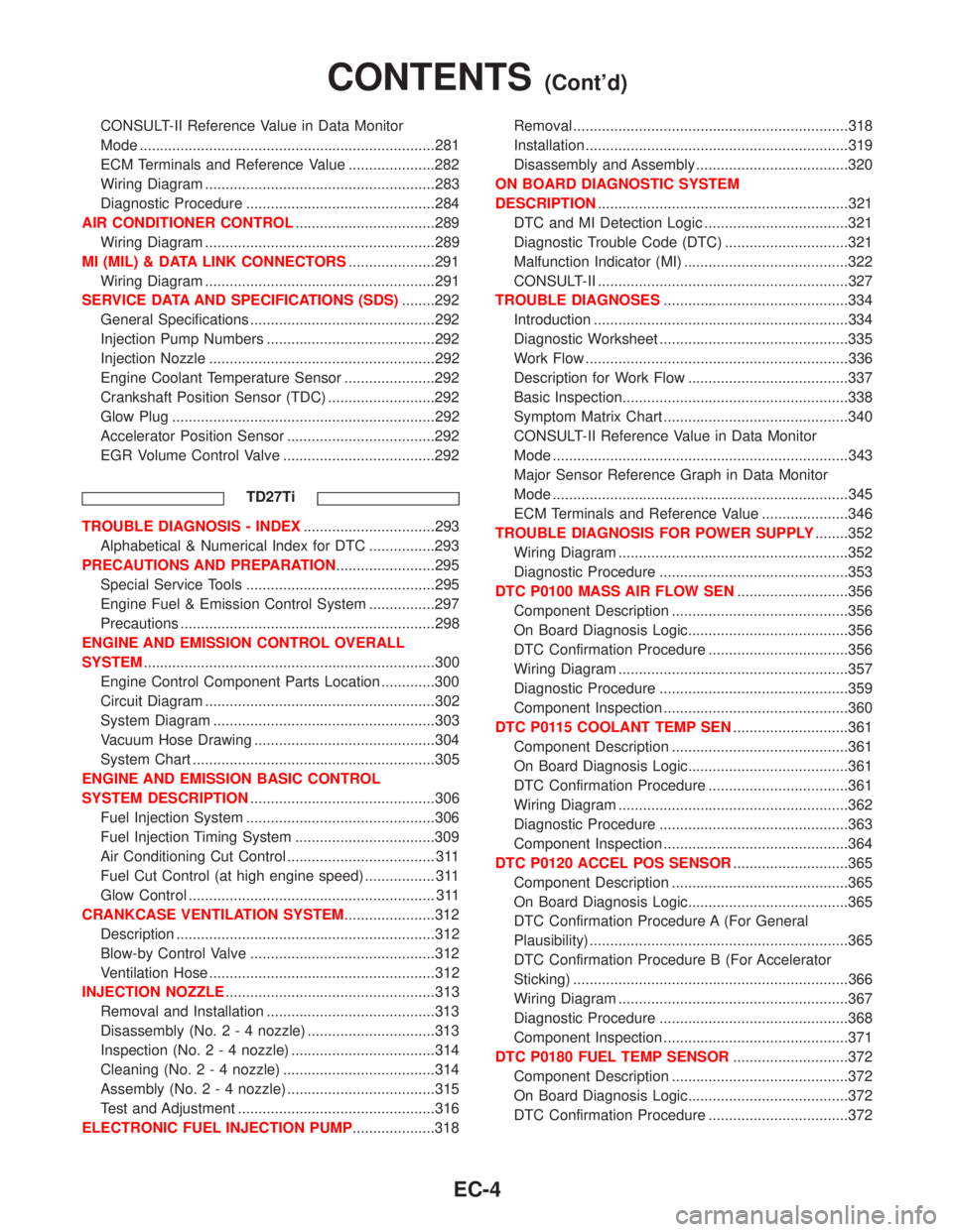
CONSULT-II Reference Value in Data Monitor
Mode ........................................................................281
ECM Terminals and Reference Value .....................282
Wiring Diagram ........................................................283
Diagnostic Procedure ..............................................284
AIR CONDITIONER CONTROL..................................289
Wiring Diagram ........................................................289
MI (MIL) & DATA LINK CONNECTORS.....................291
Wiring Diagram ........................................................291
SERVICE DATA AND SPECIFICATIONS (SDS)........292
General Specifications .............................................292
Injection Pump Numbers .........................................292
Injection Nozzle .......................................................292
Engine Coolant Temperature Sensor ......................292
Crankshaft Position Sensor (TDC) ..........................292
Glow Plug ................................................................292
Accelerator Position Sensor ....................................292
EGR Volume Control Valve .....................................292
TD27Ti
TROUBLE DIAGNOSIS - INDEX................................293
Alphabetical & Numerical Index for DTC ................293
PRECAUTIONS AND PREPARATION........................295
Special Service Tools ..............................................295
Engine Fuel & Emission Control System ................297
Precautions ..............................................................298
ENGINE AND EMISSION CONTROL OVERALL
SYSTEM.......................................................................300
Engine Control Component Parts Location .............300
Circuit Diagram ........................................................302
System Diagram ......................................................303
Vacuum Hose Drawing ............................................304
System Chart ...........................................................305
ENGINE AND EMISSION BASIC CONTROL
SYSTEM DESCRIPTION.............................................306
Fuel Injection System ..............................................306
Fuel Injection Timing System ..................................309
Air Conditioning Cut Control .................................... 311
Fuel Cut Control (at high engine speed) ................. 311
Glow Control ............................................................ 311
CRANKCASE VENTILATION SYSTEM......................312
Description ...............................................................312
Blow-by Control Valve .............................................312
Ventilation Hose .......................................................312
INJECTION NOZZLE...................................................313
Removal and Installation .........................................313
Disassembly (No.2-4nozzle) ...............................313
Inspection (No.2-4nozzle) ...................................314
Cleaning (No.2-4nozzle) .....................................314
Assembly (No.2-4nozzle) ....................................315
Test and Adjustment ................................................316
ELECTRONIC FUEL INJECTION PUMP....................318Removal ...................................................................318
Installation ................................................................319
Disassembly and Assembly .....................................320
ON BOARD DIAGNOSTIC SYSTEM
DESCRIPTION.............................................................321
DTC and MI Detection Logic ...................................321
Diagnostic Trouble Code (DTC) ..............................321
Malfunction Indicator (MI) ........................................322
CONSULT-II .............................................................327
TROUBLE DIAGNOSES.............................................334
Introduction ..............................................................334
Diagnostic Worksheet ..............................................335
Work Flow ................................................................336
Description for Work Flow .......................................337
Basic Inspection.......................................................338
Symptom Matrix Chart .............................................340
CONSULT-II Reference Value in Data Monitor
Mode ........................................................................343
Major Sensor Reference Graph in Data Monitor
Mode ........................................................................345
ECM Terminals and Reference Value .....................346
TROUBLE DIAGNOSIS FOR POWER SUPPLY........352
Wiring Diagram ........................................................352
Diagnostic Procedure ..............................................353
DTC P0100 MASS AIR FLOW SEN...........................356
Component Description ...........................................356
On Board Diagnosis Logic.......................................356
DTC Confirmation Procedure ..................................356
Wiring Diagram ........................................................357
Diagnostic Procedure ..............................................359
Component Inspection .............................................360
DTC P0115 COOLANT TEMP SEN............................361
Component Description ...........................................361
On Board Diagnosis Logic.......................................361
DTC Confirmation Procedure ..................................361
Wiring Diagram ........................................................362
Diagnostic Procedure ..............................................363
Component Inspection .............................................364
DTC P0120 ACCEL POS SENSOR............................365
Component Description ...........................................365
On Board Diagnosis Logic.......................................365
DTC Confirmation Procedure A (For General
Plausibility) ...............................................................365
DTC Confirmation Procedure B (For Accelerator
Sticking) ...................................................................366
Wiring Diagram ........................................................367
Diagnostic Procedure ..............................................368
Component Inspection .............................................371
DTC P0180 FUEL TEMP SENSOR............................372
Component Description ...........................................372
On Board Diagnosis Logic.......................................372
DTC Confirmation Procedure ..................................372
CONTENTS(Cont'd)
EC-4
Page 368 of 1767
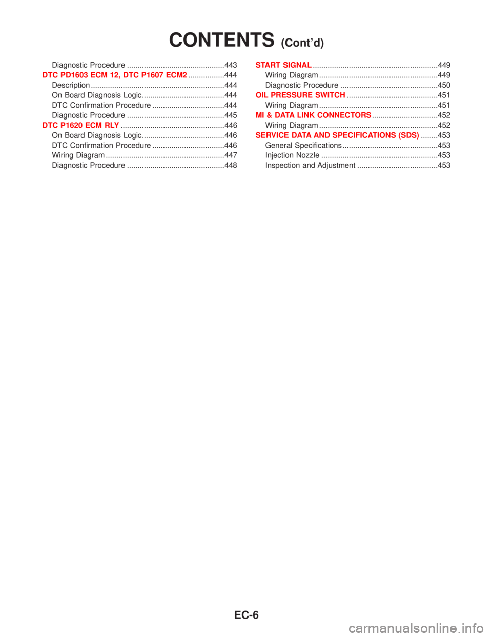
Diagnostic Procedure ..............................................443
DTC PD1603 ECM 12, DTC P1607 ECM2.................444
Description ...............................................................444
On Board Diagnosis Logic.......................................444
DTC Confirmation Procedure ..................................444
Diagnostic Procedure ..............................................445
DTC P1620 ECM RLY.................................................446
On Board Diagnosis Logic.......................................446
DTC Confirmation Procedure ..................................446
Wiring Diagram ........................................................447
Diagnostic Procedure ..............................................448START SIGNAL...........................................................449
Wiring Diagram ........................................................449
Diagnostic Procedure ..............................................450
OIL PRESSURE SWITCH...........................................451
Wiring Diagram ........................................................451
MI & DATA LINK CONNECTORS...............................452
Wiring Diagram ........................................................452
SERVICE DATA AND SPECIFICATIONS (SDS)........453
General Specifications .............................................453
Injection Nozzle .......................................................453
Inspection and Adjustment ......................................453
CONTENTS(Cont'd)
EC-6
Page 408 of 1767
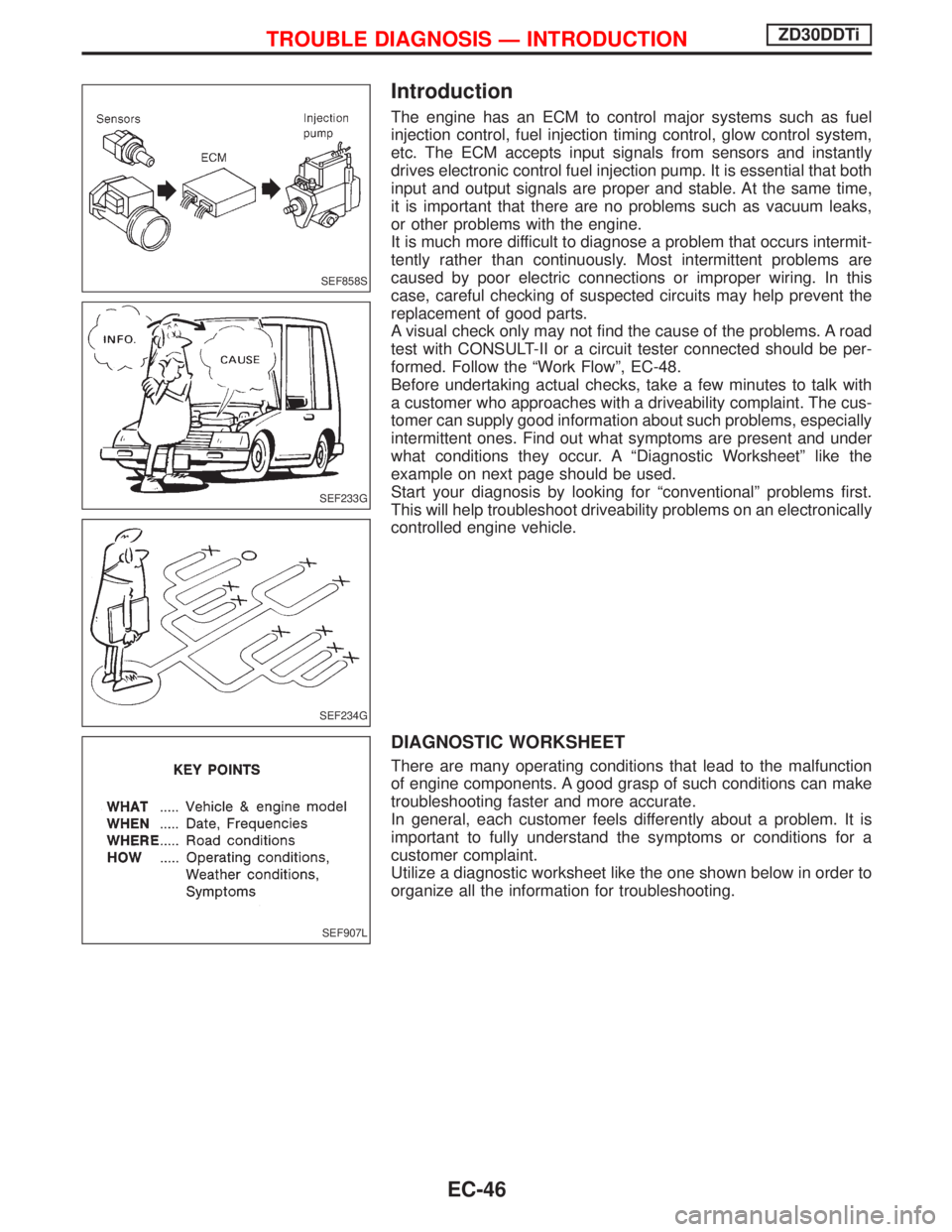
Introduction
The engine has an ECM to control major systems such as fuel
injection control, fuel injection timing control, glow control system,
etc. The ECM accepts input signals from sensors and instantly
drives electronic control fuel injection pump. It is essential that both
input and output signals are proper and stable. At the same time,
it is important that there are no problems such as vacuum leaks,
or other problems with the engine.
It is much more difficult to diagnose a problem that occurs intermit-
tently rather than continuously. Most intermittent problems are
caused by poor electric connections or improper wiring. In this
case, careful checking of suspected circuits may help prevent the
replacement of good parts.
A visual check only may not find the cause of the problems. A road
test with CONSULT-II or a circuit tester connected should be per-
formed. Follow the ªWork Flowº, EC-48.
Before undertaking actual checks, take a few minutes to talk with
a customer who approaches with a driveability complaint. The cus-
tomer can supply good information about such problems, especially
intermittent ones. Find out what symptoms are present and under
what conditions they occur. A ªDiagnostic Worksheetº like the
example on next page should be used.
Start your diagnosis by looking for ªconventionalº problems first.
This will help troubleshoot driveability problems on an electronically
controlled engine vehicle.
DIAGNOSTIC WORKSHEET
There are many operating conditions that lead to the malfunction
of engine components. A good grasp of such conditions can make
troubleshooting faster and more accurate.
In general, each customer feels differently about a problem. It is
important to fully understand the symptoms or conditions for a
customer complaint.
Utilize a diagnostic worksheet like the one shown below in order to
organize all the information for troubleshooting.
SEF858S
SEF233G
SEF234G
SEF907L
TROUBLE DIAGNOSIS Ð INTRODUCTIONZD30DDTi
EC-46
Page 418 of 1767
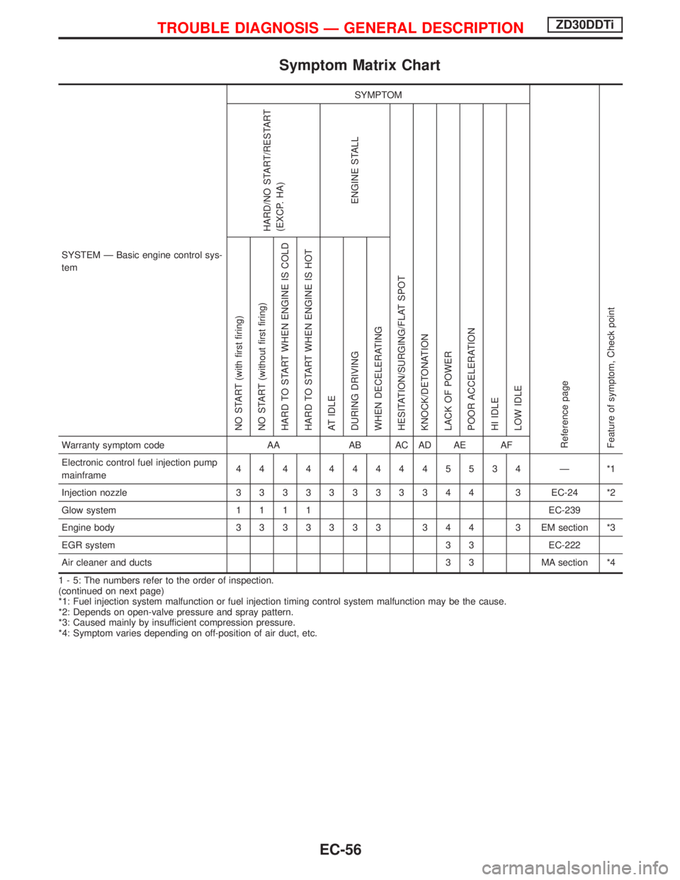
Symptom Matrix Chart
SYSTEM Ð Basic engine control sys-
temSYMPTOM
Reference page
Feature of symptom, Check pointHARD/NO START/RESTART
(EXCP. HA)
ENGINE STALL
HESITATION/SURGING/FLAT SPOT
KNOCK/DETONATION
LACK OF POWER
POOR ACCELERATION
HI IDLE
LOW IDLE NO START (with first firing)
NO START (without first firing)
HARD TO START WHEN ENGINE IS COLD
HARD TO START WHEN ENGINE IS HOT
AT IDLE
DURING DRIVING
WHEN DECELERATINGWarranty symptom code AA AB AC AD AE AF
Electronic control fuel injection pump
mainframe4444444445534 Ð *1
Injection nozzle33333333344 3EC-24 *2
Glow system1111EC-239
Engine body3333333 344 3 EMsection *3
EGR system3 3 EC-222
Air cleaner and ducts 3 3 MA section *4
1 - 5: The numbers refer to the order of inspection.
(continued on next page)
*1: Fuel injection system malfunction or fuel injection timing control system malfunction may be the cause.
*2: Depends on open-valve pressure and spray pattern.
*3: Caused mainly by insufficient compression pressure.
*4: Symptom varies depending on off-position of air duct, etc.
TROUBLE DIAGNOSIS Ð GENERAL DESCRIPTIONZD30DDTi
EC-56
Page 419 of 1767
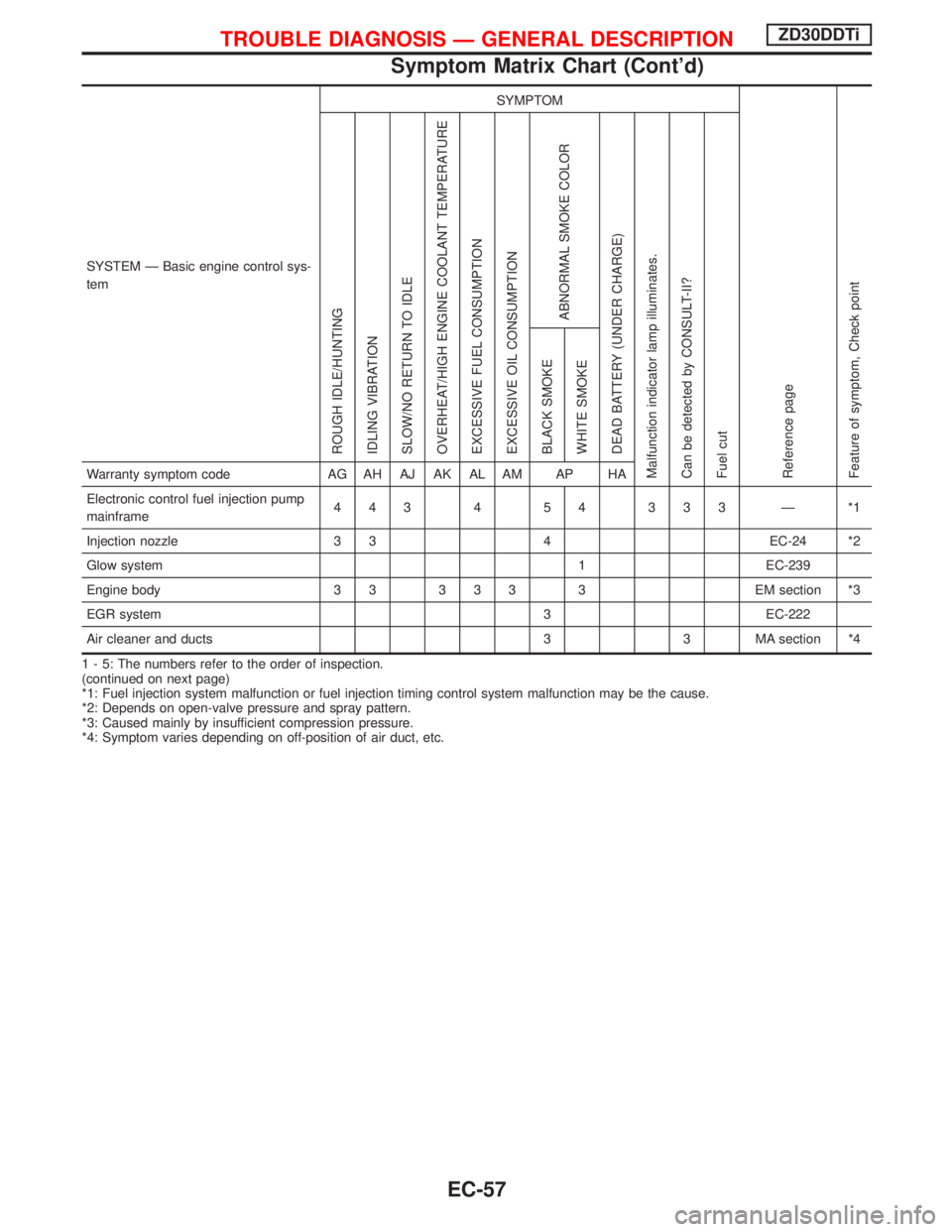
SYSTEM Ð Basic engine control sys-
temSYMPTOM
Reference page
Feature of symptom, Check pointROUGH IDLE/HUNTING
IDLING VIBRATION
SLOW/NO RETURN TO IDLE
OVERHEAT/HIGH ENGINE COOLANT TEMPERATURE
EXCESSIVE FUEL CONSUMPTION
EXCESSIVE OIL CONSUMPTION
ABNORMAL SMOKE COLOR
DEAD BATTERY (UNDER CHARGE)
Malfunction indicator lamp illuminates.
Can be detected by CONSULT-II?
Fuel cutBLACK SMOKE
WHITE SMOKEWarranty symptom code AG AH AJ AK AL AM AP HA
Electronic control fuel injection pump
mainframe443 4 54 333 Ð *1
Injection nozzle 3 3 4 EC-24 *2
Glow system 1 EC-239
Engine body 3 3 3 3 3 3 EM section *3
EGR system 3 EC-222
Air cleaner and ducts 3 3 MA section *4
1 - 5: The numbers refer to the order of inspection.
(continued on next page)
*1: Fuel injection system malfunction or fuel injection timing control system malfunction may be the cause.
*2: Depends on open-valve pressure and spray pattern.
*3: Caused mainly by insufficient compression pressure.
*4: Symptom varies depending on off-position of air duct, etc.
TROUBLE DIAGNOSIS Ð GENERAL DESCRIPTIONZD30DDTi
Symptom Matrix Chart (Cont'd)
EC-57
Page 420 of 1767
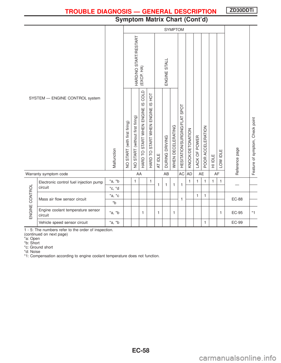
SYSTEM Ð ENGINE CONTROL system
Malfunction
SYMPTOM
Reference page
Feature of symptom, Check pointHARD/NO START/RESTART
(EXCP. HA)
ENGINE STALL
HESITATION/SURGING/FLAT SPOT
KNOCK/DETONATION
LACK OF POWER
POOR ACCELERATION
HI IDLE
LOW IDLE NO START (with first firing)
NO START (without first firing)
HARD TO START WHEN ENGINE IS COLD
HARD TO START WHEN ENGINE IS HOT
AT IDLE
DURING DRIVING
WHEN DECELERATINGWarranty symptom code AA AB AC AD AE AF
ENGINE CONTROL
Electronic control fuel injection pump
circuit*a, *b 1 1
111111111
Ð
*c, *d
Mass air flow sensor circuit*a, *c
111
EC-88
*b
Engine coolant temperature sensor
circuit*a, *b 1 1 1 1 EC-95 *1
Vehicle speed sensor circuit *a, *b 1 EC-99
1 - 5: The numbers refer to the order of inspection.
(continued on next page)
*a: Open
*b: Short
*c: Ground short
*d: Noise
*1: Compensation according to engine coolant temperature does not function.
TROUBLE DIAGNOSIS Ð GENERAL DESCRIPTIONZD30DDTi
Symptom Matrix Chart (Cont'd)
EC-58
Page 421 of 1767
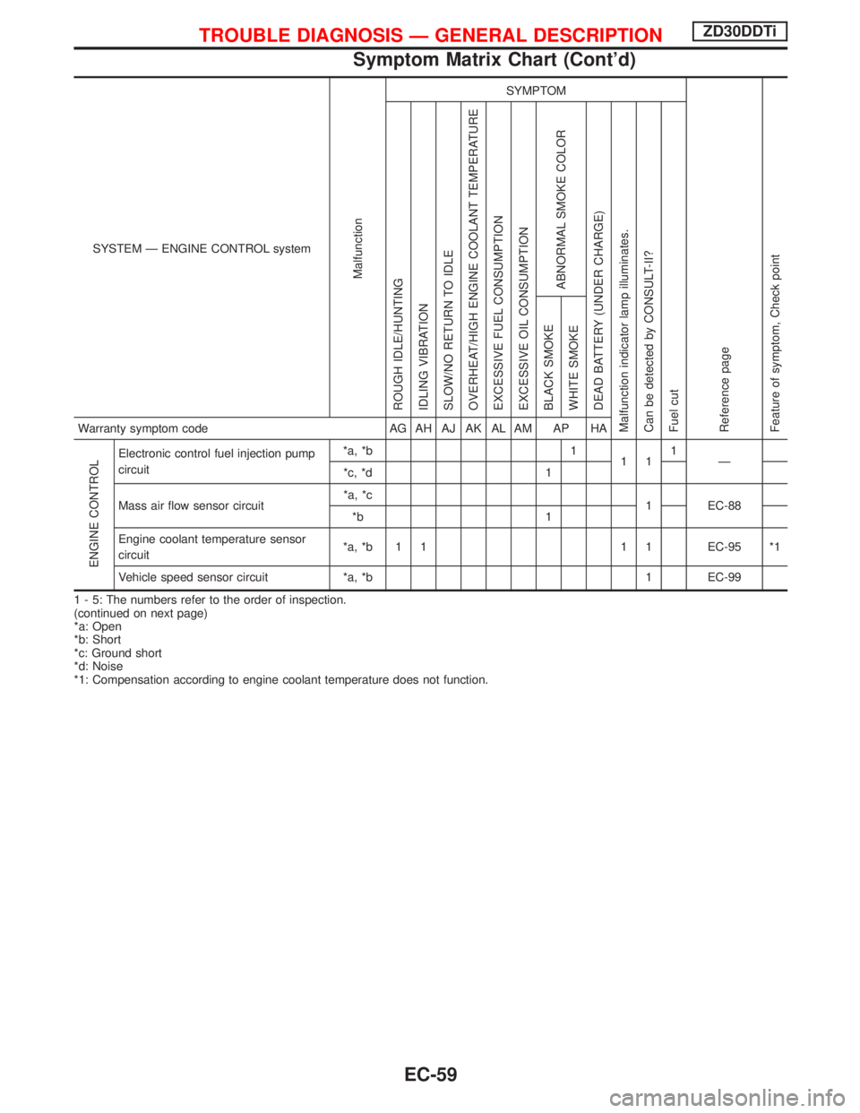
SYSTEM Ð ENGINE CONTROL system
Malfunction
SYMPTOM
Reference page
Feature of symptom, Check pointROUGH IDLE/HUNTING
IDLING VIBRATION
SLOW/NO RETURN TO IDLE
OVERHEAT/HIGH ENGINE COOLANT TEMPERATURE
EXCESSIVE FUEL CONSUMPTION
EXCESSIVE OIL CONSUMPTION
ABNORMAL SMOKE COLOR
DEAD BATTERY (UNDER CHARGE)
Malfunction indicator lamp illuminates.
Can be detected by CONSULT-II?
Fuel cutBLACK SMOKE
WHITE SMOKEWarranty symptom code AG AH AJ AK AL AM AP HA
ENGINE CONTROL
Electronic control fuel injection pump
circuit*a, *b 1
111
Ð
*c, *d 1
Mass air flow sensor circuit*a, *c
1 EC-88
*b 1
Engine coolant temperature sensor
circuit*a, *b 1 1 1 1 EC-95 *1
Vehicle speed sensor circuit *a, *b 1 EC-99
1 - 5: The numbers refer to the order of inspection.
(continued on next page)
*a: Open
*b: Short
*c: Ground short
*d: Noise
*1: Compensation according to engine coolant temperature does not function.
TROUBLE DIAGNOSIS Ð GENERAL DESCRIPTIONZD30DDTi
Symptom Matrix Chart (Cont'd)
EC-59