2002 NISSAN TERRANO general
[x] Cancel search: generalPage 48 of 1767
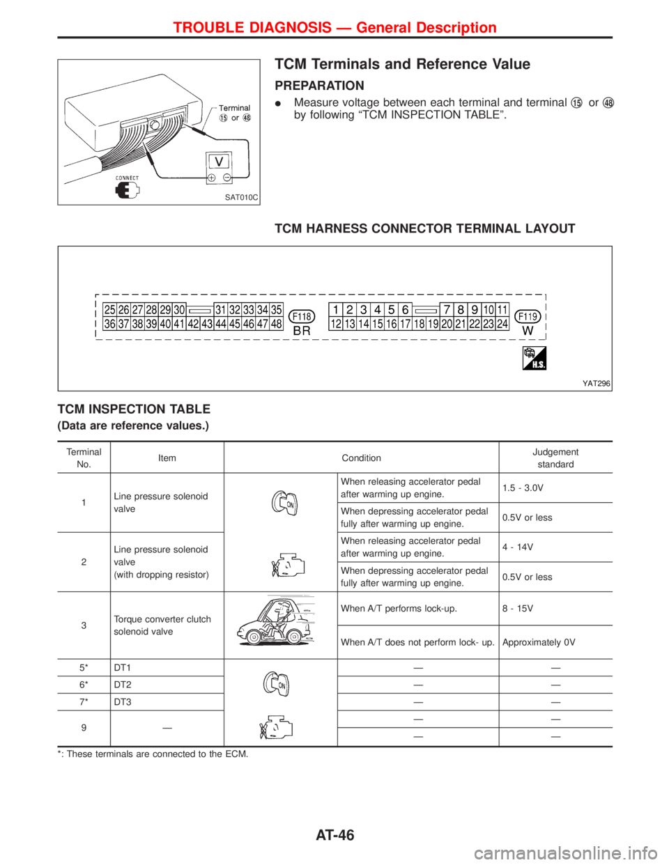
TCM Terminals and Reference Value
PREPARATION
IMeasure voltage between each terminal and terminalq15orq48
by following ªTCM INSPECTION TABLEº.
TCM HARNESS CONNECTOR TERMINAL LAYOUT
TCM INSPECTION TABLE
(Data are reference values.)
Terminal
No.Item ConditionJudgement
standard
1Line pressure solenoid
valve
When releasing accelerator pedal
after warming up engine.1.5 - 3.0V
When depressing accelerator pedal
fully after warming up engine.0.5V or less
2Line pressure solenoid
valve
(with dropping resistor)When releasing accelerator pedal
after warming up engine.4 - 14V
When depressing accelerator pedal
fully after warming up engine.0.5V or less
3Torque converter clutch
solenoid valve
When A/T performs lock-up. 8 - 15V
When A/T does not perform lock- up. Approximately 0V
5* DT1
ÐÐ
6* DT2 Ð Ð
7* DT3 Ð Ð
9ÐÐÐ
ÐÐ
*: These terminals are connected to the ECM.
SAT010C
YAT296
TROUBLE DIAGNOSIS Ð General Description
AT-46
Page 49 of 1767
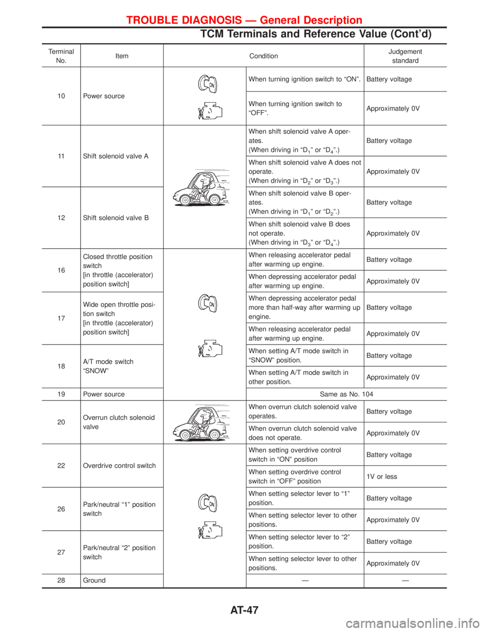
Terminal
No.Item ConditionJudgement
standard
10 Power source
When turning ignition switch to ªONº. Battery voltage
When turning ignition switch to
ªOFFº.Approximately 0V
11 Shift solenoid valve A
When shift solenoid valve A oper-
ates.
(When driving in ªD
1ºorªD4º.)Battery voltage
When shift solenoid valve A does not
operate.
(When driving in ªD
2ºorªD3º.)Approximately 0V
12 Shift solenoid valve BWhen shift solenoid valve B oper-
ates.
(When driving in ªD
1ºorªD2º.)Battery voltage
When shift solenoid valve B does
not operate.
(When driving in ªD
3ºorªD4º.)Approximately 0V
16Closed throttle position
switch
[in throttle (accelerator)
position switch]
When releasing accelerator pedal
after warming up engine.Battery voltage
When depressing accelerator pedal
after warming up engine.Approximately 0V
17Wide open throttle posi-
tion switch
[in throttle (accelerator)
position switch]When depressing accelerator pedal
more than half-way after warming up
engine.Battery voltage
When releasing accelerator pedal
after warming up engine.Approximately 0V
18A/T mode switch
ªSNOWºWhen setting A/T mode switch in
ªSNOWº position.Battery voltage
When setting A/T mode switch in
other position.Approximately 0V
19 Power source Same as No. 104
20Overrun clutch solenoid
valve
When overrun clutch solenoid valve
operates.Battery voltage
When overrun clutch solenoid valve
does not operate.Approximately 0V
22 Overdrive control switch
When setting overdrive control
switch in ªONº positionBattery voltage
When setting overdrive control
switch in ªOFFº position1V or less
26Park/neutral ª1º position
switchWhen setting selector lever to ª1º
position.Battery voltage
When setting selector lever to other
positions.Approximately 0V
27Park/neutral ª2º position
switchWhen setting selector lever to ª2º
position.Battery voltage
When setting selector lever to other
positions.Approximately 0V
28 Ground Ð Ð
TROUBLE DIAGNOSIS Ð General Description
TCM Terminals and Reference Value (Cont'd)
AT-47
Page 50 of 1767
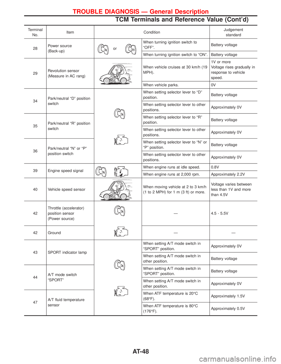
Terminal
No.Item ConditionJudgement
standard
28Power source
(Back-up)
or
When turning ignition switch to
ªOFFº.Battery voltage
When turning ignition switch to ªONº. Battery voltage
29Revolution sensor
(Measure in AC rang)
When vehicle cruises at 30 km/h (19
MPH).1V or more
Voltage rises gradually in
response to vehicle
speed.
When vehicle parks. 0V
34Park/neutral ªDº position
switch
When setting selector lever to ªDº
position.Battery voltage
When setting selector lever to other
positions.Approximately 0V
35Park/neutral ªRº position
switchWhen setting selector lever to ªRº
position.Battery voltage
When setting selector lever to other
positions.Approximately 0V
36Park/neutral ªNº or ªPº
position switchWhen setting selector lever to ªNº or
ªPº position.Battery voltage
When setting selector lever to other
positions.Approximately 0V
39 Engine speed signal
When engine runs at idle speed. 0.8V
When engine runs at 2,000 rpm. Approximately 2.2V
40 Vehicle speed sensor
When moving vehicle at 2 to 3 km/h
(1 to 2 MPH) for1m(3ft)ormore.Voltage varies between
less than 1V and more
than 4.5V
42Throttle (accelerator)
position sensor
(Power source)
Ð 4.5 - 5.5V
42 Ground Ð Ð
43 SPORT indicator lamp
When setting A/T mode switch in
ªSPORTº position.Approximately 0V
When setting A/T mode switch in
other position.Battery voltage
44A/T mode switch
ªSPORTºWhen setting A/T mode switch in
ªSPORTº position.Battery voltage
When setting A/T mode switch in
other position.Approximately 0V
47A/T fluid temperature
sensorWhen ATF temperature is 20ÉC
(68ÉF).Approximately 1.5V
When ATF temperature is 80ÉC
(176ÉF).Approximately 0.5V
TROUBLE DIAGNOSIS Ð General Description
TCM Terminals and Reference Value (Cont'd)
AT-48
Page 198 of 1767
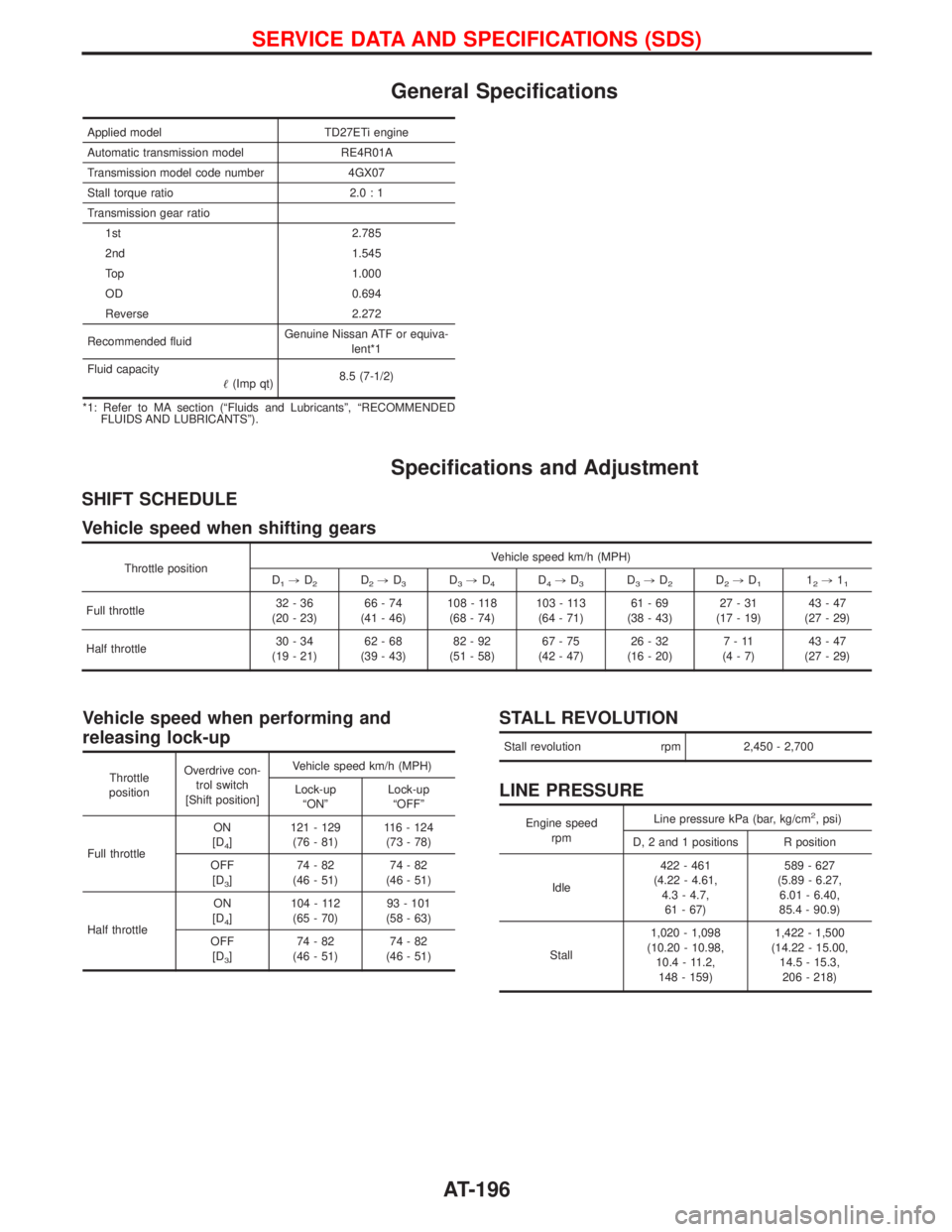
General Specifications
Applied model TD27ETi engine
Automatic transmission model RE4R01A
Transmission model code number 4GX07
Stall torque ratio 2.0 : 1
Transmission gear ratio
1st 2.785
2nd 1.545
Top 1.000
OD 0.694
Reverse 2.272
Recommended fluidGenuine Nissan ATF or equiva-
lent*1
Fluid capacity
(Imp qt)8.5 (7-1/2)
*1: Refer to MA section (ªFluids and Lubricantsº, ªRECOMMENDED
FLUIDS AND LUBRICANTSº).
Specifications and Adjustment
SHIFT SCHEDULE
Vehicle speed when shifting gears
Throttle positionVehicle speed km/h (MPH)
D1,D2D2,D3D3,D4D4,D3D3,D2D2,D112,11
Full throttle32-36
(20 - 23)66-74
(41 - 46)108 - 118
(68 - 74)103 - 113
(64 - 71)61-69
(38 - 43)27-31
(17 - 19)43-47
(27 - 29)
Half throttle30-34
(19 - 21)62-68
(39 - 43)82-92
(51 - 58)67-75
(42 - 47)26-32
(16 - 20)7-11
(4-7)43-47
(27 - 29)
Vehicle speed when performing and
releasing lock-up
Throttle
positionOverdrive con-
trol switch
[Shift position]Vehicle speed km/h (MPH)
Lock-up
ªONºLock-up
ªOFFº
Full throttleON
[D
4]121 - 129
(76 - 81)116 - 124
(73 - 78)
OFF
[D
3]74-82
(46 - 51)74-82
(46 - 51)
Half throttleON
[D
4]104 - 112
(65 - 70)93 - 101
(58 - 63)
OFF
[D
3]74-82
(46 - 51)74-82
(46 - 51)
STALL REVOLUTION
Stall revolution rpm 2,450 - 2,700
LINE PRESSURE
Engine speed
rpmLine pressure kPa (bar, kg/cm2, psi)
D, 2 and 1 positions R position
Idle422 - 461
(4.22 - 4.61,
4.3 - 4.7,
61 - 67)589 - 627
(5.89 - 6.27,
6.01 - 6.40,
85.4 - 90.9)
Stall1,020 - 1,098
(10.20 - 10.98,
10.4 - 11.2,
148 - 159)1,422 - 1,500
(14.22 - 15.00,
14.5 - 15.3,
206 - 218)
SERVICE DATA AND SPECIFICATIONS (SDS)
AT-196
Page 204 of 1767
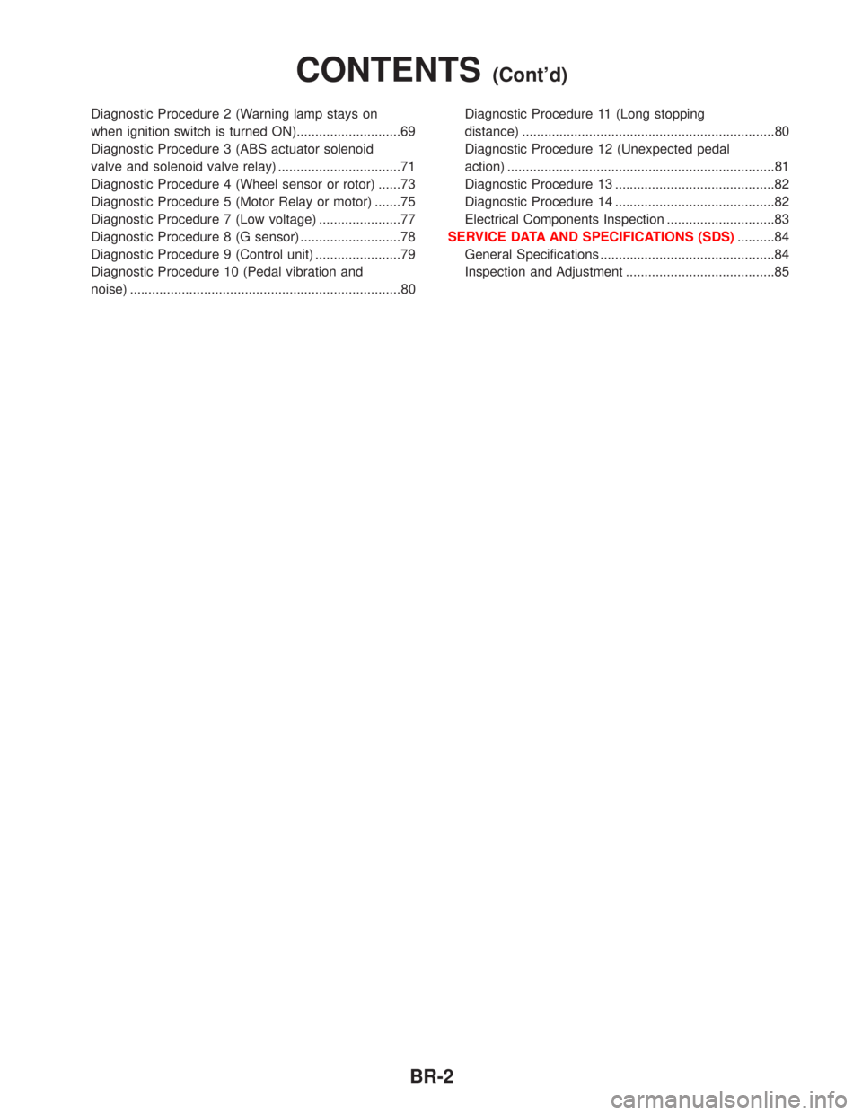
Diagnostic Procedure 2 (Warning lamp stays on
when ignition switch is turned ON)............................69
Diagnostic Procedure 3 (ABS actuator solenoid
valve and solenoid valve relay) .................................71
Diagnostic Procedure 4 (Wheel sensor or rotor) ......73
Diagnostic Procedure 5 (Motor Relay or motor) .......75
Diagnostic Procedure 7 (Low voltage) ......................77
Diagnostic Procedure 8 (G sensor) ...........................78
Diagnostic Procedure 9 (Control unit) .......................79
Diagnostic Procedure 10 (Pedal vibration and
noise) .........................................................................80Diagnostic Procedure 11 (Long stopping
distance) ....................................................................80
Diagnostic Procedure 12 (Unexpected pedal
action) ........................................................................81
Diagnostic Procedure 13 ...........................................82
Diagnostic Procedure 14 ...........................................82
Electrical Components Inspection .............................83
SERVICE DATA AND SPECIFICATIONS (SDS)..........84
General Specifications ...............................................84
Inspection and Adjustment ........................................85
CONTENTS(Cont'd)
BR-2
Page 286 of 1767
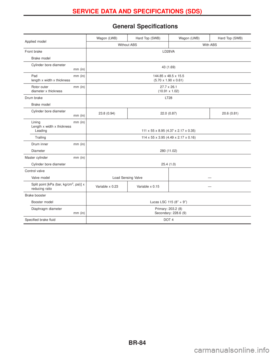
General Specifications
Applied modelWagon (LWB) Hard Top (SWB) Wagon (LWB) Hard Top (SWB)
Without ABS With ABS
Front brakeLD28VA
Brake model
Cylinder bore diameter
mm (in)43 (1.69)
Pad mm (in)
length x width x thickness144.85 x 48.5 x 15.5
(5.70 x 1.90 x 0.61)
Rotor outer mm (in)
diameter x thickness27.7 x 26.1
(10.91 x 1.02)
Drum brakeLT28
Brake model
Cylinder bore diameter
mm (in)23.8 (0.94) 22.0 (0.87) 20.6 (0.81)
Lining mm (in)
Length x width x thickness
Leading 111 x 55 x 8.95 (4.37 x 2.17 x 0.35)
Trailing 114 x 55 x 3.95 (4.49 x 2.17 x 0.16)
Drum inner mm (in)
Diameter280 (11.02)
Master cylinder mm (in)
Cylinder bore diameter 25.4 (1.0)
Control valve
Valve model Load Sensing Valve Ð
Split point [kPa (bar, kg/cm
2, psi)] x
reducing ratioVariable x 0.23 Variable x 0.15 Ð
Brake booster
Booster model Lucas LSC 115 (8²+9²)
Diaphragm diameter
mm (in)Primary: 203.2 (8)
Secondary: 228.6 (9)
Specified brake fluidDOT 4
SERVICE DATA AND SPECIFICATIONS (SDS)
BR-84
Page 349 of 1767
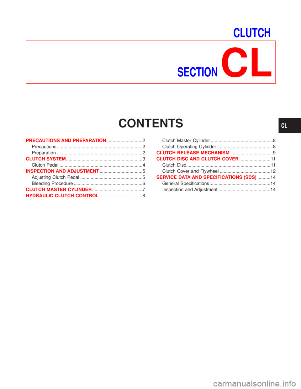
CLUTCH
SECTION
CL
CONTENTS
PRECAUTIONS AND PREPARATION............................2
Precautions ..................................................................2
Preparation ..................................................................2
CLUTCH SYSTEM...........................................................3
Clutch Pedal ................................................................4
INSPECTION AND ADJUSTMENT.................................5
Adjusting Clutch Pedal ................................................5
Bleeding Procedure .....................................................6
CLUTCH MASTER CYLINDER.......................................7
HYDRAULIC CLUTCH CONTROL.................................8Clutch Master Cylinder ................................................8
Clutch Operating Cylinder ...........................................8
CLUTCH RELEASE MECHANISM.................................9
CLUTCH DISC AND CLUTCH COVER........................ 11
Clutch Disc................................................................. 11
Clutch Cover and Flywheel .......................................12
SERVICE DATA AND SPECIFICATIONS (SDS)..........14
General Specifications ...............................................14
Inspection and Adjustment ........................................14
Page 362 of 1767
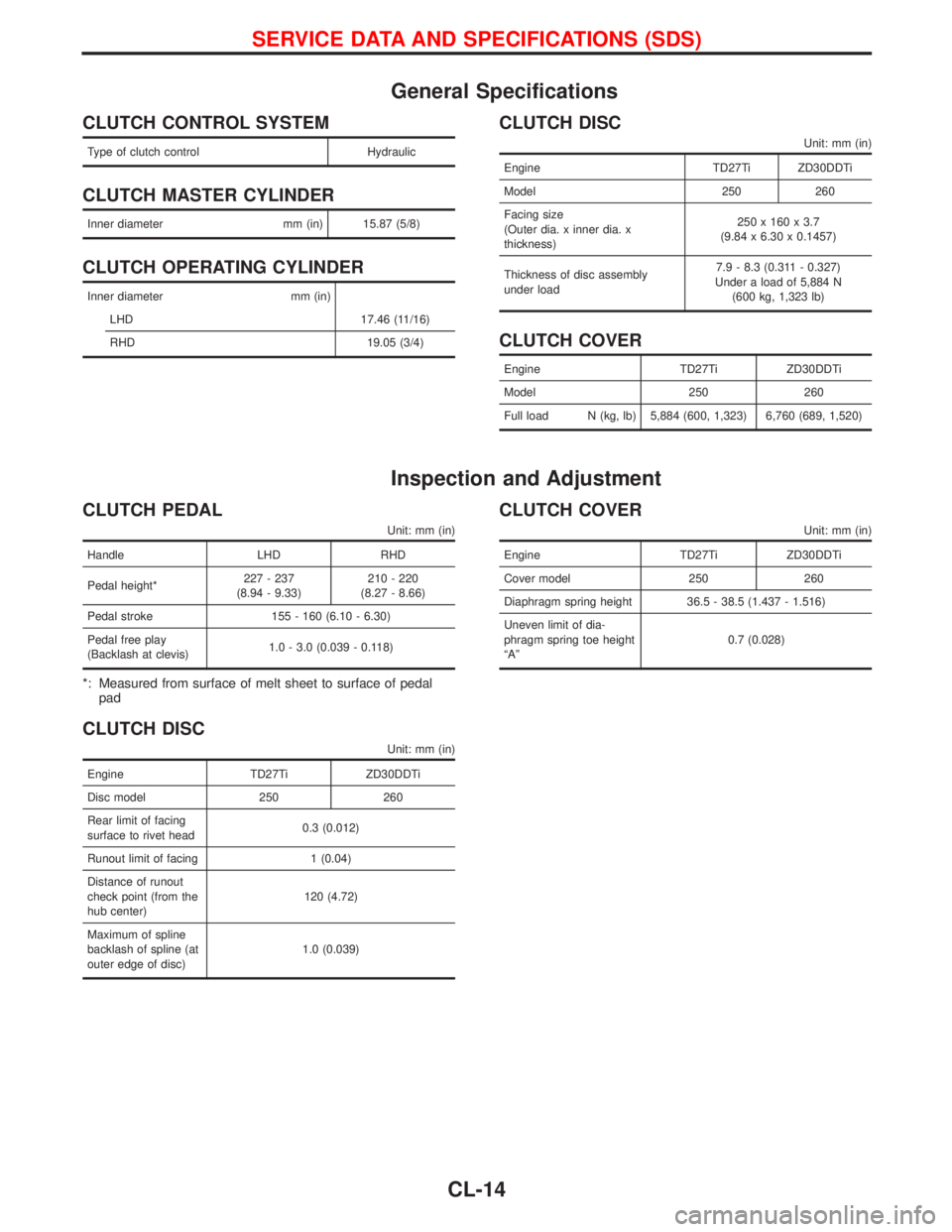
General Specifications
CLUTCH CONTROL SYSTEM
Type of clutch control Hydraulic
CLUTCH MASTER CYLINDER
Inner diameter mm (in) 15.87 (5/8)
CLUTCH OPERATING CYLINDER
Inner diameter mm (in)
LHD 17.46 (11/16)
RHD 19.05 (3/4)
CLUTCH DISC
Unit: mm (in)
Engine TD27Ti ZD30DDTi
Model 250 260
Facing size
(Outer dia. x inner dia. x
thickness)250 x 160 x 3.7
(9.84 x 6.30 x 0.1457)
Thickness of disc assembly
under load7.9 - 8.3 (0.311 - 0.327)
Under a load of 5,884 N
(600 kg, 1,323 lb)
CLUTCH COVER
Engine TD27Ti ZD30DDTi
Model 250 260
Full load N (kg, lb) 5,884 (600, 1,323) 6,760 (689, 1,520)
Inspection and Adjustment
CLUTCH PEDAL
Unit: mm (in)
Handle LHD RHD
Pedal height*227 - 237
(8.94 - 9.33)210 - 220
(8.27 - 8.66)
Pedal stroke 155 - 160 (6.10 - 6.30)
Pedal free play
(Backlash at clevis)1.0 - 3.0 (0.039 - 0.118)
*: Measured from surface of melt sheet to surface of pedal
pad
CLUTCH DISC
Unit: mm (in)
Engine TD27Ti ZD30DDTi
Disc model 250 260
Rear limit of facing
surface to rivet head0.3 (0.012)
Runout limit of facing 1 (0.04)
Distance of runout
check point (from the
hub center)120 (4.72)
Maximum of spline
backlash of spline (at
outer edge of disc)1.0 (0.039)
CLUTCH COVER
Unit: mm (in)
Engine TD27Ti ZD30DDTi
Cover model 250 260
Diaphragm spring height 36.5 - 38.5 (1.437 - 1.516)
Uneven limit of dia-
phragm spring toe height
ªAº0.7 (0.028)
SERVICE DATA AND SPECIFICATIONS (SDS)
CL-14