2002 NISSAN TERRANO general
[x] Cancel search: generalPage 1125 of 1767
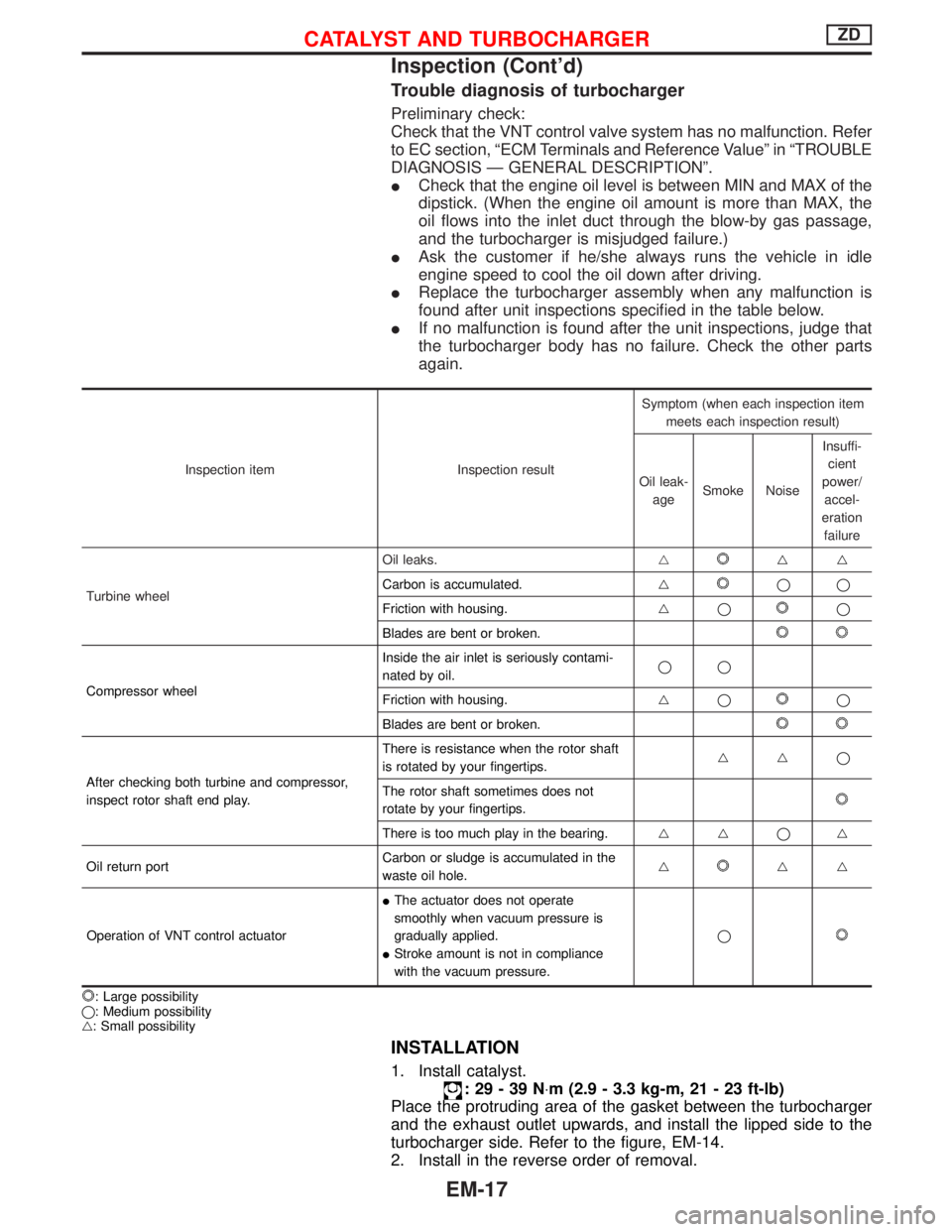
Trouble diagnosis of turbocharger
Preliminary check:
Check that the VNT control valve system has no malfunction. Refer
to EC section, ªECM Terminals and Reference Valueº in ªTROUBLE
DIAGNOSIS Ð GENERAL DESCRIPTIONº.
ICheck that the engine oil level is between MIN and MAX of the
dipstick. (When the engine oil amount is more than MAX, the
oil flows into the inlet duct through the blow-by gas passage,
and the turbocharger is misjudged failure.)
IAsk the customer if he/she always runs the vehicle in idle
engine speed to cool the oil down after driving.
IReplace the turbocharger assembly when any malfunction is
found after unit inspections specified in the table below.
IIf no malfunction is found after the unit inspections, judge that
the turbocharger body has no failure. Check the other parts
again.
Inspection item Inspection resultSymptom (when each inspection item
meets each inspection result)
Oil leak-
ageSmoke NoiseInsuffi-
cient
power/
accel-
eration
failure
Turbine wheelOil leaks.g
gg
Carbon is accumulated.g
qq
Friction with housing.gq
q
Blades are bent or broken.
Compressor wheelInside the air inlet is seriously contami-
nated by oil.qq
Friction with housing.gqq
Blades are bent or broken.
After checking both turbine and compressor,
inspect rotor shaft end play.There is resistance when the rotor shaft
is rotated by your fingertips.ggq
The rotor shaft sometimes does not
rotate by your fingertips.
There is too much play in the bearing.ggqg
Oil return portCarbon or sludge is accumulated in the
waste oil hole.g
gg
Operation of VNT control actuatorIThe actuator does not operate
smoothly when vacuum pressure is
gradually applied.
IStroke amount is not in compliance
with the vacuum pressure.q
: Large possibility
q: Medium possibility
g: Small possibility
INSTALLATION
1. Install catalyst.
:29-39N×m (2.9 - 3.3 kg-m, 21 - 23 ft-lb)
Place the protruding area of the gasket between the turbocharger
and the exhaust outlet upwards, and install the lipped side to the
turbocharger side. Refer to the figure, EM-14.
2. Install in the reverse order of removal.
CATALYST AND TURBOCHARGERZD
Inspection (Cont'd)
EM-17
Page 1192 of 1767
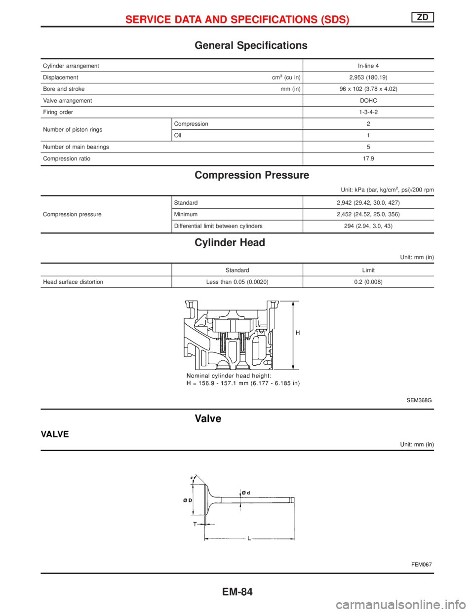
General Specifications
Cylinder arrangementIn-line 4
Displacementcm
3(cu in) 2,953 (180.19)
Bore and strokemm (in) 96 x 102 (3.78 x 4.02)
Valve arrangementDOHC
Firing order1-3-4-2
Number of piston ringsCompression 2
Oil1
Number of main bearings5
Compression ratio17.9
Compression Pressure
Unit: kPa (bar, kg/cm2, psi)/200 rpm
Compression pressureStandard 2,942 (29.42, 30.0, 427)
Minimum 2,452 (24.52, 25.0, 356)
Differential limit between cylinders 294 (2.94, 3.0, 43)
Cylinder Head
Unit: mm (in)
Standard Limit
Head surface distortion Less than 0.05 (0.0020) 0.2 (0.008)
SEM368G
Valve
VA LV E
Unit: mm (in)
FEM067
SERVICE DATA AND SPECIFICATIONS (SDS)ZD
EM-84
Page 1215 of 1767
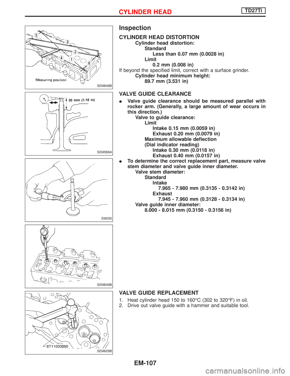
Inspection
CYLINDER HEAD DISTORTION
Cylinder head distortion:
Standard
Less than 0.07 mm (0.0028 in)
Limit
0.2 mm (0.008 in)
If beyond the specified limit, correct with a surface grinder.
Cylinder head minimum height:
89.7 mm (3.531 in)
VALVE GUIDE CLEARANCE
IValve guide clearance should be measured parallel with
rocker arm. (Generally, a large amount of wear occurs in
this direction.)
Valve to guide clearance:
Limit
Intake 0.15 mm (0.0059 in)
Exhaust 0.20 mm (0.0079 in)
Maximum allowable deflection
(Dial indicator reading)
Intake 0.30 mm (0.0118 in)
Exhaust 0.40 mm (0.0157 in)
ITo determine the correct replacement part, measure valve
stem diameter and valve guide inner diameter.
Valve stem diameter:
Standard
Intake
7.965 - 7.980 mm (0.3135 - 0.3142 in)
Exhaust
7.945 - 7.960 mm (0.3128 - 0.3134 in)
Valve guide inner diameter:
8.000 - 8.015 mm (0.3150 - 0.3156 in)
VALVE GUIDE REPLACEMENT
1. Heat cylinder head 150 to 160ÉC (302 to 320ÉF) in oil.
2. Drive out valve guide with a hammer and suitable tool.
SEM648B
SEM586A
EM030
SEM649B
SEM628B
CYLINDER HEADTD27Ti
EM-107
Page 1251 of 1767
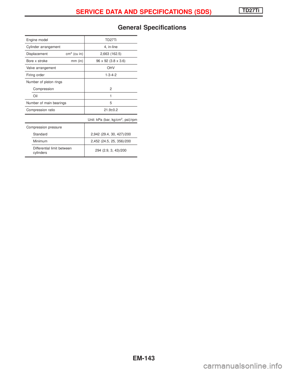
General Specifications
Engine model TD27Ti
Cylinder arrangement 4, in-line
Displacement cm
3(cu in) 2,663 (162.5)
Bore x stroke mm (in) 96 x 92 (3.8 x 3.6)
Valve arrangement OHV
Firing order 1-3-4-2
Number of piston rings
Compression 2
Oil 1
Number of main bearings 5
Compression ratio 21.9 0.2
Unit: kPa (bar, kg/cm
2, psi)/rpm
Compression pressure
Standard 2,942 (29.4, 30, 427)/200
Minimum 2,452 (24.5, 25, 356)/200
Differential limit between
cylinders294 (2.9, 3, 43)/200
SERVICE DATA AND SPECIFICATIONS (SDS)TD27Ti
EM-143
Page 1259 of 1767
FRONT AXLE & FRONT SUSPENSION
SECTION
FA
CONTENTS
PRECAUTIONS...............................................................2
PREPARATION................................................................3
FRONT AXLE AND FRONT SUSPENSION...................4
CHECK AND ADJUSTMENT..........................................5
Front Axle and Front Suspension Parts ......................5
Front Wheel Bearing....................................................6
Front Wheel Alignment ................................................8
Drive Shaft .................................................................12
FRONT AXLE................................................................13
FRONT AXLE - Auto-lock Free-running Hub.............14
Removal and Installation ...........................................14
Inspection...................................................................14
Trouble-shooting ........................................................15
FRONT AXLE - Wheel Hub and Rotor Disc...............18
Removal and Installation ...........................................18
Disassembly...............................................................18
Inspection...................................................................19
Assembly ...................................................................19
FRONT AXLE - Knuckle Spindle.................................20
Removal .....................................................................20Inspection...................................................................21
Installation ..................................................................21
FRONT AXLE - Drive Shaft..........................................22
Removal and Installation ...........................................22
Removal .....................................................................22
Disassembly...............................................................24
Inspection...................................................................25
Assembly ...................................................................25
Installation ..................................................................28
FRONT SUSPENSION..................................................29
Shock Absorber .........................................................30
Torsion Bar.................................................................30
Stabilizer Bar .............................................................33
Upper Link .................................................................33
Compression Rod ......................................................35
Lower Link .................................................................35
Upper Ball Joint and Lower Ball Joint .......................36
SERVICE DATA AND SPECIFICATIONS (SDS)..........38
General Specifications ...............................................38
Inspection and Adjustment ........................................39
Page 1296 of 1767
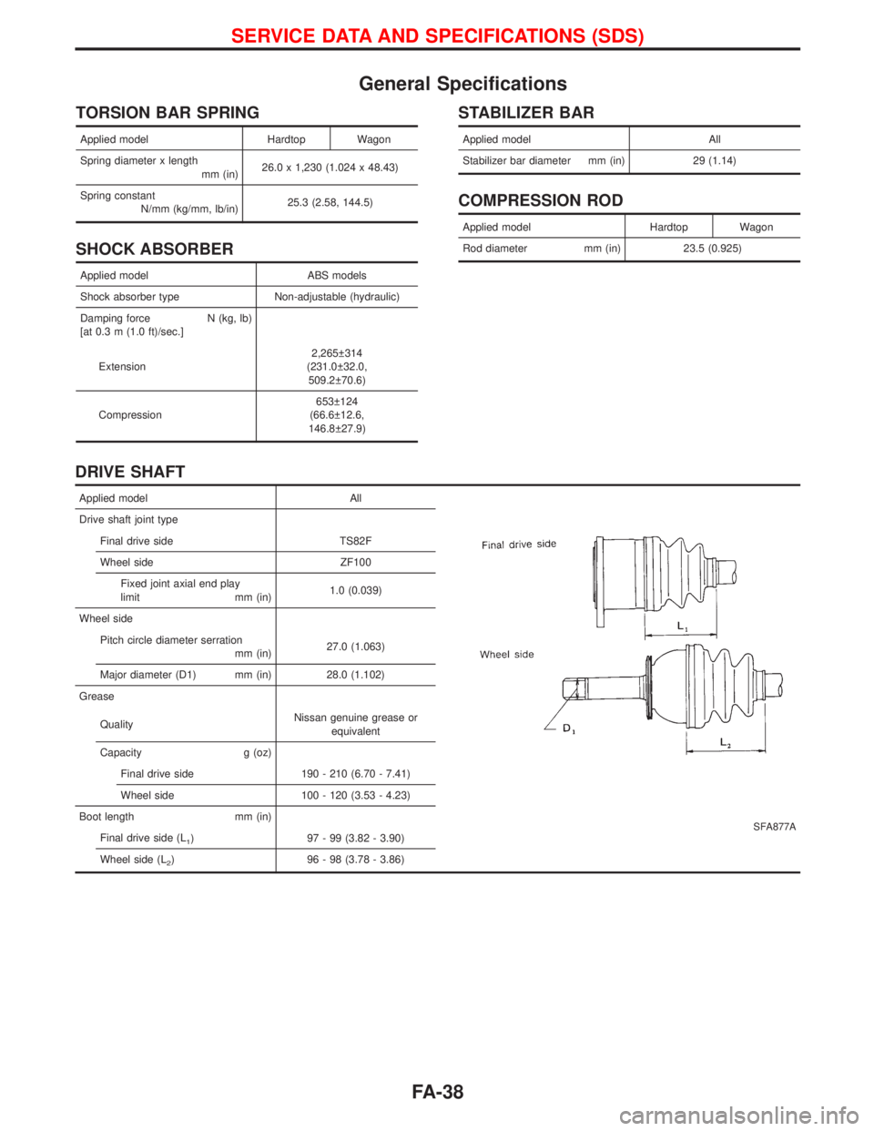
General Specifications
TORSION BAR SPRING
Applied model Hardtop Wagon
Spring diameter x length
mm (in)26.0 x 1,230 (1.024 x 48.43)
Spring constant
N/mm (kg/mm, lb/in)25.3 (2.58, 144.5)
SHOCK ABSORBER
Applied model ABS models
Shock absorber type Non-adjustable (hydraulic)
Damping force N (kg, lb)
[at 0.3 m (1.0 ft)/sec.]
Extension2,265 314
(231.0 32.0,
509.2 70.6)
Compression653 124
(66.6 12.6,
146.8 27.9)
STABILIZER BAR
Applied model All
Stabilizer bar diameter mm (in) 29 (1.14)
COMPRESSION ROD
Applied model Hardtop Wagon
Rod diameter mm (in) 23.5 (0.925)
DRIVE SHAFT
Applied model All
SFA877A
Drive shaft joint type
Final drive side TS82F
Wheel side ZF100
Fixed joint axial end play
limit mm (in)1.0 (0.039)
Wheel side
Pitch circle diameter serration
mm (in)27.0 (1.063)
Major diameter (D1) mm (in) 28.0 (1.102)
Grease
QualityNissan genuine grease or
equivalent
Capacity g (oz)
Final drive side 190 - 210 (6.70 - 7.41)
Wheel side 100 - 120 (3.53 - 4.23)
Boot length mm (in)
Final drive side (L
1) 97 - 99 (3.82 - 3.90)
Wheel side (L
2) 96 - 98 (3.78 - 3.86)
SERVICE DATA AND SPECIFICATIONS (SDS)
FA-38
Page 1316 of 1767
GENERAL INFORMATION
SECTION
GI
CONTENTS
PRECAUTIONS...............................................................2
Supplemental Restraint System (SRS)²AIR
BAG²and²SEAT BELT PRE-TENSIONER²
(Dual Air Bag System) .................................................3
Precautions for NATS ..................................................4
Precautions for Multiport Fuel Injection System
or Engine Control System ...........................................5
Precautions for Catalyst ..............................................5
Precautions for Turbocharger ......................................5
Precautions for Fuel ....................................................6
Precautions for Engine Oils .........................................6
HOW TO USE THIS MANUAL........................................8
HOW TO READ WIRING DIAGRAMS..........................10
Sample/Wiring Diagram - EXAMPL - ........................10
Description .................................................................12
HOW TO CHECK TERMINAL.......................................19
How to Probe Connectors .........................................19
How to Check Enlarged Contact Spring of
Terminal .....................................................................20
Waterproof Connector Inspection ..............................21
Terminal Lock Inspection ...........................................21
HOW TO PERFORM EFFICIENT DIAGNOSIS FOR
AN ELECTRICAL INCIDENT........................................22Work Flow ..................................................................22
Incident Simulation Tests ...........................................23
HOW TO FOLLOW FLOW CHART IN TROUBLE
DIAGNOSES..................................................................25
CONSULT-II CHECKING SYSTEM...............................26
General ......................................................................26
Function and System Application ..............................26
Nickel Metal Hydride Battery Replacement...............27
Checking Equipment..................................................27
IDENTIFICATION INFORMATION.................................28
Model Variation ..........................................................28
Identification Number .................................................29
Dimensions ................................................................31
Wheels and Tires .......................................................31
LIFTING POINTS AND TOW TRUCK TOWING...........32
Garage Jack and Safety Stand .................................32
Screw Jack ................................................................32
4-pole Lift ...................................................................33
Tow Truck Towing ......................................................33
ISO 15031-2 TERMINOLOGY LIST..............................35
ISO 15031-2 Terminology List ...................................35
TIGHTENING TORQUE OF STANDARD BOLTS........38
Page 1341 of 1767
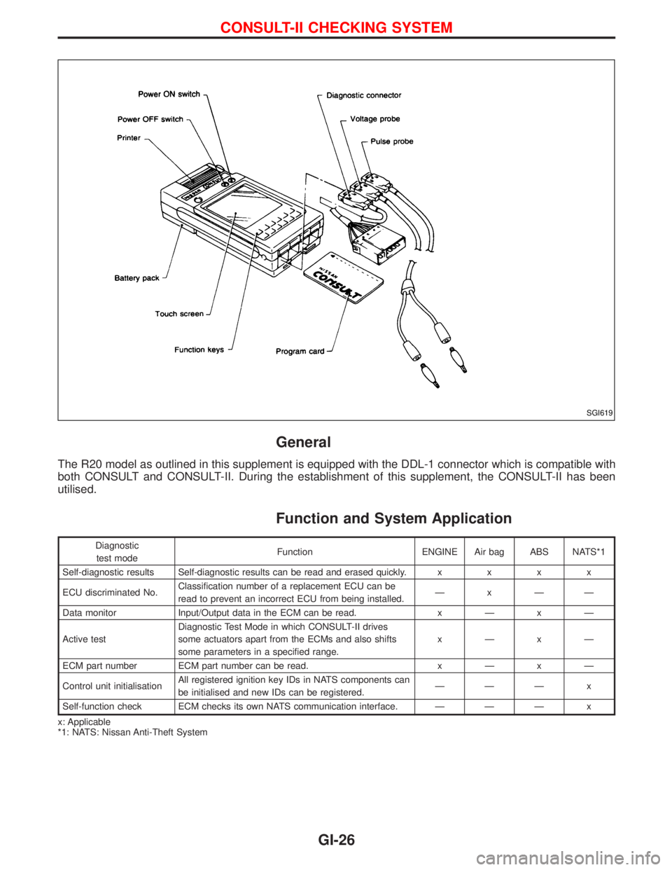
General
The R20 model as outlined in this supplement is equipped with the DDL-1 connector which is compatible with
both CONSULT and CONSULT-II. During the establishment of this supplement, the CONSULT-II has been
utilised.
Function and System Application
Diagnostic
test modeFunction ENGINE Air bag ABS NATS*1
Self-diagnostic results Self-diagnostic results can be read and erased quickly.xxxx
ECU discriminated No.Classification number of a replacement ECU can be
read to prevent an incorrect ECU from being installed.ÐxÐÐ
Data monitor Input/Output data in the ECM can be read.xÐxÐ
Active testDiagnostic Test Mode in which CONSULT-II drives
some actuators apart from the ECMs and also shifts
some parameters in a specified range.xÐxÐ
ECM part number ECM part number can be read.xÐxÐ
Control unit initialisationAll registered ignition key IDs in NATS components can
be initialised and new IDs can be registered.ÐÐÐ x
Self-function check ECM checks its own NATS communication interface. Ð Ð Ð x
x: Applicable
*1: NATS: Nissan Anti-Theft System
SGI619
CONSULT-II CHECKING SYSTEM
GI-26