2002 NISSAN TERRANO general
[x] Cancel search: generalPage 1354 of 1767
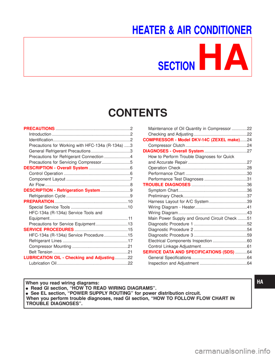
HEATER & AIR CONDITIONER
SECTION
HA
CONTENTS
PRECAUTIONS...............................................................2
Introduction ..................................................................2
Identification .................................................................2
Precautions for Working with HFC-134a (R-134a) .....3
General Refrigerant Precautions .................................3
Precautions for Refrigerant Connection ......................4
Precautions for Servicing Compressor ........................5
DESCRIPTION - Overall System...................................6
Control Operation ........................................................6
Component Layout ......................................................7
Air Flow ........................................................................8
DESCRIPTION - Refrigeration System.........................9
Refrigeration Cycle ......................................................9
PREPARATION..............................................................10
Special Service Tools ................................................10
HFC-134a (R-134a) Service Tools and
Equipment .................................................................. 11
Precautions for Service Equipment ...........................13
SERVICE PROCEDURES.............................................15
HFC-134a (R-134a) Service Procedure ....................15
Refrigerant Lines .......................................................17
Compressor Mounting ...............................................21
Belt Tension ...............................................................21
LUBRICATION OIL - Checking and Adjusting...........22
Lubrication Oil ............................................................22Maintenance of Oil Quantity in Compressor .............22
Checking and Adjusting .............................................22
COMPRESSOR - Model DKV-14C (ZEXEL make)......24
Compressor Clutch ....................................................24
DIAGNOSES - Overall System....................................27
How to Perform Trouble Diagnoses for Quick
and Accurate Repair ..................................................27
Operation Check ........................................................28
Performance Chart ....................................................30
Performance Test Diagnoses ....................................31
TROUBLE DIAGNOSES...............................................36
Symptom Chart ..........................................................36
Preliminary Check......................................................37
Harness Layout for A/C System ................................39
Wiring Diagram - Heater............................................41
Wiring Diagram ..........................................................43
Main Power Supply and Ground Circuit Check ........51
Diagnostic Procedure 1 .............................................52
Diagnostic Procedure 2 .............................................54
Diagnostic Procedure 3 .............................................59
Electrical Components Inspection .............................60
Control Linkage Adjustment.......................................61
SERVICE DATA AND SPECIFICATIONS (SDS)..........64
General Specifications ...............................................64
Inspection and Adjustment ........................................64
When you read wiring diagrams:
IRead GI section, ªHOW TO READ WIRING DIAGRAMSº.
ISee EL section, ªPOWER SUPPLY ROUTINGº for power distribution circuit.
When you perform trouble diagnoses, read GI section, ªHOW TO FOLLOW FLOW CHART IN
TROUBLE DIAGNOSESº.
Page 1356 of 1767
Precautions for Working with HFC-134a
(R-134a)
WARNING:
ICFC-12 (R-12) refrigerant and HFC-134a (R-134a) refrigerant must never be mixed, even in the
smallest amounts, as they are incompatible with each other. If the refrigerants are mixed, com-
pressor failure is likely to occur.
IUse only specified lubrication oil for the HFC-134a (R-134a) A/C system and HFC-134a (R-134a)
components. If lubrication oil other than that specified is used, compressor failure is likely to
occur.
IThe specified HFC-134a (R-134a) lubrication oil absorbs moisture from the atmosphere at a rapid
rate, therefore the following handling precautions must be observed:
a: When removing refrigerant components from a vehicle, immediately cap (seal) the component
to minimize the entry of moisture from the atmosphere.
b: When installing refrigerant components to a vehicle, do not remove the caps (unseal) until
just before connecting the components. Also, complete the connection of all refrigerant loop
components as quickly as possible to minimize the entry of moisture into the system.
c: Use the specified lubrication oil from a sealed container only. Containers must be re-sealed
immediately after dispensing the lubrication oil. Lubrication oil in containers which are not
properly sealed will become moisture saturated, and such lubrication oil is no longer suitable
for use and should be properly disposed of.
d: Avoid breathing A/C refrigerant and lubricant vapor or mist. Exposure may irritate eyes, nose
and throat. Use only approved recovery/recycling equipment to discharge HFC-134a (R-134a)
system. If accidental system discharge occurs, ventilate work area before resuming service.
Additional health and safety information may be obtained from refrigerant and lubricant
manufacturers.
e: Do not allow lubrication oil (Nissan A/C System Oil Type S or Type R) to come in contact with
styrofoam parts. Damage may result.
General Refrigerant Precautions
WARNING:
IDo not release refrigerant into the air. Use approved recovery/recycling equipment to capture the
refrigerant every time an air conditioning system is discharged.
IAlways wear eye and hand protection (goggles and gloves) when working with any refrigerant or
air conditioning system.
IDo not store or heat refrigerant containers above 52ÉC (125ÉF).
IDo not heat a refrigerant container with an open flame; if container warming is required, place the
bottom of the container in a warm pail of water.
IDo not drop, puncture, or incinerate refrigerant containers.
IKeep refrigerant away from open flames: poisonous gas will be produced if refrigerant burns.
IRefrigerant will displace oxygen, therefore be certain to work in well ventilated areas to prevent
suffocation.
IDo not introduce compressed air to any refrigerant container or refrigerant component.
PRECAUTIONS
HA-3
Page 1367 of 1767
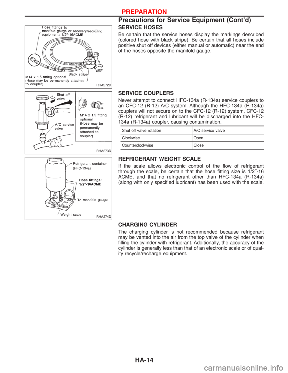
SERVICE HOSES
Be certain that the service hoses display the markings described
(colored hose with black stripe). Be certain that all hoses include
positive shut off devices (either manual or automatic) near the end
of the hoses opposite the manifold gauge.
SERVICE COUPLERS
Never attempt to connect HFC-134a (R-134a) service couplers to
an CFC-12 (R-12) A/C system. Although the HFC-134a (R-134a)
couplers will not secure on to the CFC-12 (R-12) system, CFC-12
(R-12) refrigerant and lubricant will be discharged into the HFC-
134a (R-134a) coupler, causing contamination.
Shut off valve rotation A/C service valve
Clockwise Open
Counterclockwise Close
REFRIGERANT WEIGHT SCALE
If the scale allows electronic control of the flow of refrigerant
through the scale, be certain that the hose fitting size is 1/2²-16
ACME, and that no refrigerant other than HFC-134a (R-134a)
(along with only specified lubricant) has been used with the scale.
CHARGING CYLINDER
The charging cylinder is not recommended because refrigerant
may be vented into the air from the top valve of the cylinder when
filling the cylinder with refrigerant. Additionally, the accuracy of the
cylinder is generally less than that of an electronic scale or of qual-
ity recycle/recharge equipment.
RHA272D
RHA273D
RHA274D
PREPARATION
Precautions for Service Equipment (Cont'd)
HA-14
Page 1417 of 1767
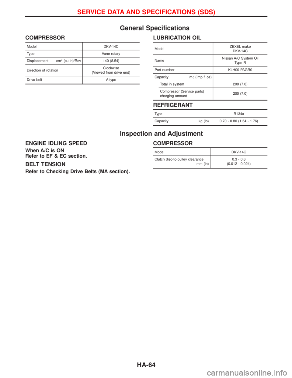
General Specifications
COMPRESSOR
Model DKV-14C
Type Vane rotary
Displacement cm
3(cu in)/Rev 140 (8.54)
Direction of rotationClockwise
(Viewed from drive end)
Drive belt A type
LUBRICATION OIL
ModelZEXEL make
DKV-14C
NameNissan A/C System Oil
Type R
Part number KLH00-PAGR0
Capacity m(Imp fl oz)
Total in system 200 (7.0)
Compressor (Service parts)
charging amount200 (7.0)
REFRIGERANT
Type R134a
Capacity kg (lb) 0.70 - 0.80 (1.54 - 1.76)
Inspection and Adjustment
ENGINE IDLING SPEED
When A/C is ON
Refer to EF & EC section.
BELT TENSION
Refer to Checking Drive Belts (MA section).
COMPRESSOR
Model DKV-14C
Clutch disc-to-pulley clearance
mm (in)0.3 - 0.6
(0.012 - 0.024)
SERVICE DATA AND SPECIFICATIONS (SDS)
HA-64
Page 1420 of 1767
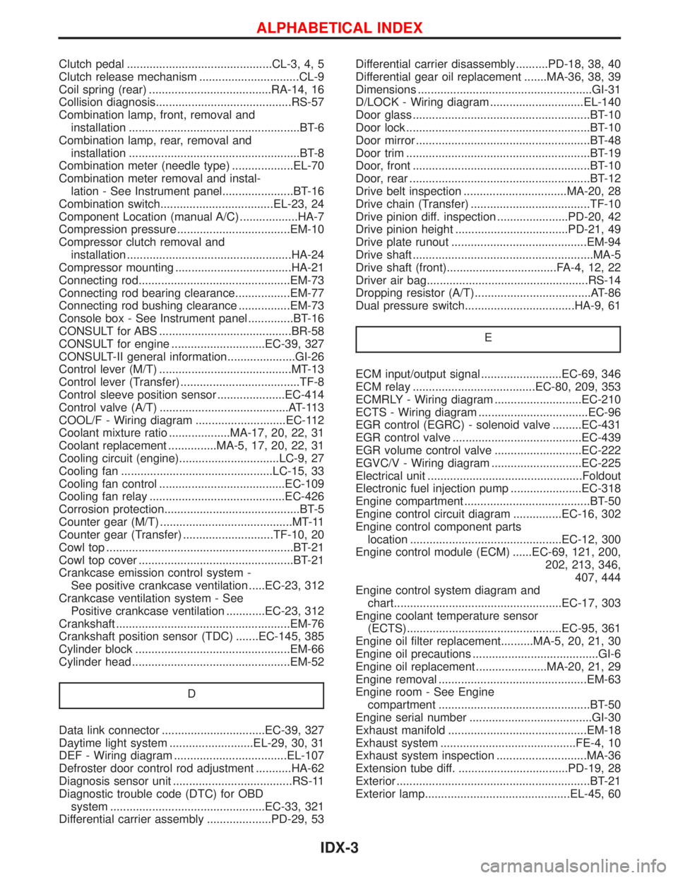
Clutch pedal .............................................CL-3, 4, 5
Clutch release mechanism ...............................CL-9
Coil spring (rear) ......................................RA-14, 16
Collision diagnosis..........................................RS-57
Combination lamp, front, removal and
installation .....................................................BT-6
Combination lamp, rear, removal and
installation .....................................................BT-8
Combination meter (needle type) ...................EL-70
Combination meter removal and instal-
lation - See Instrument panel......................BT-16
Combination switch...................................EL-23, 24
Component Location (manual A/C) ..................HA-7
Compression pressure ...................................EM-10
Compressor clutch removal and
installation ...................................................HA-24
Compressor mounting ....................................HA-21
Connecting rod...............................................EM-73
Connecting rod bearing clearance.................EM-77
Connecting rod bushing clearance ................EM-73
Console box - See Instrument panel ..............BT-16
CONSULT for ABS .........................................BR-58
CONSULT for engine .............................EC-39, 327
CONSULT-II general information.....................GI-26
Control lever (M/T) .........................................MT-13
Control lever (Transfer) .....................................TF-8
Control sleeve position sensor .....................EC-414
Control valve (A/T) ........................................AT-113
COOL/F - Wiring diagram ............................EC-112
Coolant mixture ratio ...................MA-17, 20, 22, 31
Coolant replacement ...............MA-5, 17, 20, 22, 31
Cooling circuit (engine)...............................LC-9, 27
Cooling fan ...............................................LC-15, 33
Cooling fan control .......................................EC-109
Cooling fan relay ..........................................EC-426
Corrosion protection..........................................BT-5
Counter gear (M/T) .........................................MT-11
Counter gear (Transfer) ............................TF-10, 20
Cowl top ..........................................................BT-21
Cowl top cover ................................................BT-21
Crankcase emission control system -
See positive crankcase ventilation .....EC-23, 312
Crankcase ventilation system - See
Positive crankcase ventilation ............EC-23, 312
Crankshaft ......................................................EM-76
Crankshaft position sensor (TDC) .......EC-145, 385
Cylinder block ................................................EM-66
Cylinder head .................................................EM-52
D
Data link connector ................................EC-39, 327
Daytime light system ..........................EL-29, 30, 31
DEF - Wiring diagram ...................................EL-107
Defroster door control rod adjustment ...........HA-62
Diagnosis sensor unit .....................................RS-11
Diagnostic trouble code (DTC) for OBD
system ................................................EC-33, 321
Differential carrier assembly ....................PD-29, 53Differential carrier disassembly..........PD-18, 38, 40
Differential gear oil replacement .......MA-36, 38, 39
Dimensions ......................................................GI-31
D/LOCK - Wiring diagram .............................EL-140
Door glass .......................................................BT-10
Door lock .........................................................BT-10
Door mirror ......................................................BT-48
Door trim .........................................................BT-19
Door, front .......................................................BT-10
Door, rear ........................................................BT-12
Drive belt inspection ................................MA-20, 28
Drive chain (Transfer) .....................................TF-10
Drive pinion diff. inspection ......................PD-20, 42
Drive pinion height ...................................PD-21, 49
Drive plate runout ..........................................EM-94
Drive shaft ........................................................MA-5
Drive shaft (front)..................................FA-4, 12, 22
Driver air bag..................................................RS-14
Dropping resistor (A/T)....................................AT-86
Dual pressure switch..................................HA-9, 61
E
ECM input/output signal .........................EC-69, 346
ECM relay ......................................EC-80, 209, 353
ECMRLY - Wiring diagram ...........................EC-210
ECTS - Wiring diagram ..................................EC-96
EGR control (EGRC) - solenoid valve .........EC-431
EGR control valve ........................................EC-439
EGR volume control valve ...........................EC-222
EGVC/V - Wiring diagram ............................EC-225
Electrical unit ................................................Foldout
Electronic fuel injection pump ......................EC-318
Engine compartment .......................................BT-50
Engine control circuit diagram ...............EC-16, 302
Engine control component parts
location ...............................................EC-12, 300
Engine control module (ECM) ......EC-69, 121, 200,
202, 213, 346,
407, 444
Engine control system diagram and
chart....................................................EC-17, 303
Engine coolant temperature sensor
(ECTS)................................................EC-95, 361
Engine oil filter replacement..........MA-5, 20, 21, 30
Engine oil precautions .......................................GI-6
Engine oil replacement ......................MA-20, 21, 29
Engine removal ..............................................EM-63
Engine room - See Engine
compartment ...............................................BT-50
Engine serial number ......................................GI-30
Exhaust manifold ...........................................EM-18
Exhaust system ..........................................FE-4, 10
Exhaust system inspection ............................MA-36
Extension tube diff. ..................................PD-19, 28
Exterior ............................................................BT-21
Exterior lamp.............................................EL-45, 60
ALPHABETICAL INDEX
IDX-3
Page 1423 of 1767
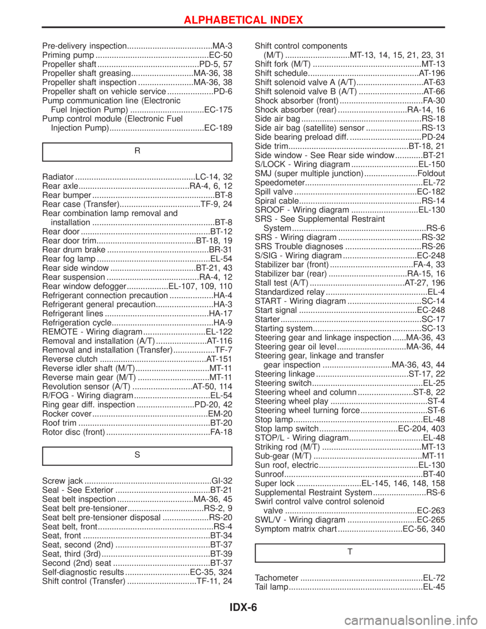
Pre-delivery inspection.....................................MA-3
Priming pump .................................................EC-50
Propeller shaft ............................................PD-5, 57
Propeller shaft greasing...........................MA-36, 38
Propeller shaft inspection ........................MA-36, 38
Propeller shaft on vehicle service ....................PD-6
Pump communication line (Electronic
Fuel Injection Pump) ................................EC-175
Pump control module (Electronic Fuel
Injection Pump).........................................EC-189
R
Radiator ....................................................LC-14, 32
Rear axle................................................RA-4, 6, 12
Rear bumper .....................................................BT-8
Rear case (Transfer)...................................TF-9, 24
Rear combination lamp removal and
installation .....................................................BT-8
Rear door ........................................................BT-12
Rear door trim...........................................BT-18, 19
Rear drum brake ............................................BR-31
Rear fog lamp .................................................EL-54
Rear side window .....................................BT-21, 43
Rear suspension ........................................RA-4, 12
Rear window defogger..................EL-107, 109, 110
Refrigerant connection precaution ...................HA-4
Refrigerant general precaution.........................HA-3
Refrigerant lines .............................................HA-17
Refrigeration cycle............................................HA-9
REMOTE - Wiring diagram ...........................EL-122
Removal and installation (A/T) ......................AT-116
Removal and installation (Transfer) ..................TF-7
Reverse clutch ..............................................AT-151
Reverse idler shaft (M/T)................................MT-11
Reverse main gear (M/T) ...............................MT-11
Revolution sensor (A/T) ..........................AT-50, 114
R/FOG - Wiring diagram .................................EL-54
Ring gear diff. inspection .........................PD-20, 42
Rocker cover ..................................................EM-20
Roof trim .........................................................BT-20
Rotor disc (front) .............................................FA-18
S
Screw jack .......................................................GI-32
Seal - See Exterior .........................................BT-21
Seat belt inspection .................................MA-36, 45
Seat belt pre-tensioner.................................RS-2, 9
Seat belt pre-tensioner disposal ....................RS-20
Seat belt, front ..................................................RS-4
Seat, front .......................................................BT-34
Seat, second (2nd) .........................................BT-37
Seat, third (3rd) ...............................................BT-39
Second (2nd) seat ..........................................BT-37
Self-diagnostic results ............................EC-35, 324
Shift control (Transfer) ..............................TF-11, 24Shift control components
(M/T) ............................MT-13, 14, 15, 21, 23, 31
Shift fork (M/T) ...............................................MT-13
Shift schedule................................................AT-196
Shift solenoid valve A (A/T).............................AT-63
Shift solenoid valve B (A/T) ............................AT-66
Shock absorber (front) ....................................FA-30
Shock absorber (rear) ..............................RA-14, 16
Side air bag ....................................................RS-18
Side air bag (satellite) sensor ........................RS-13
Side bearing preload diff. ...............................PD-24
Side trim....................................................BT-18, 21
Side window - See Rear side window ............BT-21
S/LOCK - Wiring diagram .............................EL-150
SMJ (super multiple junction) .......................Foldout
Speedometer...................................................EL-72
Spill valve .....................................................EC-182
Spiral cable.....................................................RS-14
SROOF - Wiring diagram .............................EL-130
SRS - See Supplemental Restraint
System ..........................................................RS-6
SRS - Wiring diagram ....................................RS-32
SRS Trouble diagnoses .................................RS-26
S/SIG - Wiring diagram ................................EC-248
Stabilizer bar (front) ....................................FA-4, 33
Stabilizer bar (rear) ..................................RA-15, 16
Stall test (A/T) .........................................AT-27, 196
Standardized relay ............................................EL-4
START - Wiring diagram ................................SC-14
Start signal ...................................................EC-248
Starter .............................................................SC-17
Starting system...............................................SC-13
Steering gear and linkage inspection ......MA-36, 43
Steering gear oil level ..............................MA-36, 44
Steering gear, linkage and transfer
gear inspection ..............................MA-36, 43, 44
Steering linkage ........................................ST-17, 22
Steering switch................................................EL-25
Steering wheel and column ........................ST-8, 22
Steering wheel play ..........................................ST-4
Steering wheel turning force .............................ST-6
Stop lamp ........................................................EL-48
Stop lamp switch ..................................EC-204, 403
STOP/L - Wiring diagram................................EL-48
Striking rod (M/T) ...........................................MT-13
Sub-gear (M/T) ...............................................MT-11
Sun roof, electric ...........................................EL-130
Sunroof............................................................BT-40
Super lock ............................EL-145, 146, 148, 158
Supplemental Restraint System .......................RS-6
Swirl control valve control solenoid
valve .........................................................EC-263
SWL/V - Wiring diagram ..............................EC-265
Symptom matrix chart ............................EC-56, 340
T
Tachometer .....................................................EL-72
Tail lamp ..........................................................EL-45
ALPHABETICAL INDEX
IDX-6
Page 1460 of 1767
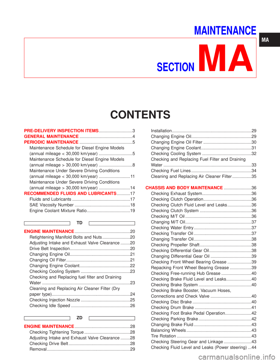
MAINTENANCE
SECTION
MA
CONTENTS
PRE-DELIVERY INSPECTION ITEMS............................3
GENERAL MAINTENANCE............................................4
PERIODIC MAINTENANCE............................................5
Maintenance Schedule for Diesel Engine Models
(annual mileage < 30,000 km/year) ............................5
Maintenance Schedule for Diesel Engine Models
(annual mileage > 30,000 km/year) ............................8
Maintenance Under Severe Driving Conditions
(annual mileage < 30,000 km/year) .......................... 11
Maintenance Under Severe Driving Conditions
(annual mileage > 30,000 km/year) ..........................14
RECOMMENDED FLUIDS AND LUBRICANTS...........17
Fluids and Lubricants ................................................17
SAE Viscosity Number ..............................................18
Engine Coolant Mixture Ratio....................................19
TD
ENGINE MAINTENANCE..............................................20
Retightening Manifold Bolts and Nuts .......................20
Adjusting Intake and Exhaust Valve Clearance ........20
Drive Belt Inspection..................................................20
Changing Engine Oil..................................................21
Changing Oil Filter .....................................................21
Changing Engine Coolant..........................................22
Checking Cooling System .........................................23
Checking and Replacing fuel filter and Draining
Water .........................................................................23
Cleaning and Replacing Air Cleaner Filter (Dry
paper type).................................................................24
Checking Injection Nozzle .........................................25
Checking Idle Speed .................................................26
ZD
ENGINE MAINTENANCE..............................................28
Checking Tightening Torque ......................................28
Adjusting Intake and Exhaust Valve Clearance ........28
Checking Drive Belt ...................................................28
Removal .....................................................................29Installation ..................................................................29
Changing Engine Oil..................................................29
Changing Engine Oil Filter ........................................30
Changing Engine Coolant..........................................31
Checking Cooling System .........................................32
Checking and Replacing Fuel Filter and Draining
Water .........................................................................33
Checking Fuel Lines ..................................................34
Cleaning and Replacing Air Cleaner Filter ................35
CHASSIS AND BODY MAINTENANCE.......................36
Checking Exhaust System.........................................36
Checking Clutch Operation........................................36
Checking Clutch Fluid Level and Leaks ....................36
Checking Clutch System ...........................................36
Checking M/T Oil .......................................................36
Changing M/T Oil.......................................................37
Checking Water Entry ................................................37
Checking Transfer Oil ................................................37
Changing Transfer Oil................................................38
Checking Propeller Shaft ...........................................38
Checking Differential Gear Oil ...................................38
Changing Differential Gear Oil ..................................39
Checking Front Wheel Bearing Grease ....................39
Repacking Front Wheel Bearing Grease ..................39
Checking Free-running Hub Grease .........................40
Checking Brake Fluid Level and Leaks.....................40
Checking Brake System ............................................40
Checking Brake Booster, Vacuum Hoses,
Connections and Check Valve ..................................40
Checking Disc Brake .................................................40
Checking Drum Brake ...............................................41
Checking Foot Brake Pedal Operation......................42
Checking Parking Brake ............................................42
Changing Brake Fluid ................................................43
Balancing Wheels ......................................................43
Tire Rotation ..............................................................43
Checking Steering Gear and Linkage .......................43
Checking Fluid Level and Leaks (Power steering) ...44
Page 1463 of 1767
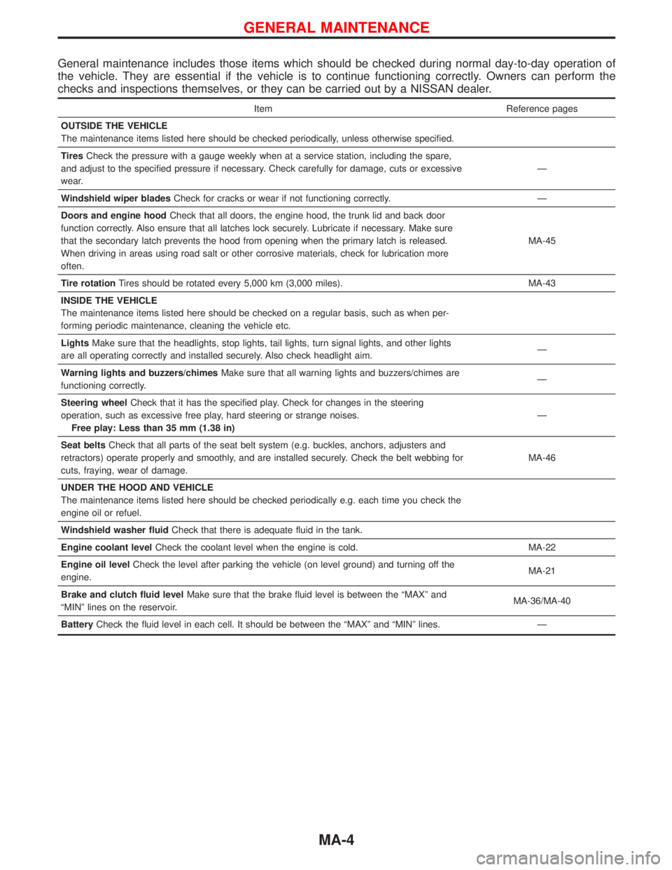
General maintenance includes those items which should be checked during normal day-to-day operation of
the vehicle. They are essential if the vehicle is to continue functioning correctly. Owners can perform the
checks and inspections themselves, or they can be carried out by a NISSAN dealer.
Item Reference pages
OUTSIDE THE VEHICLE
The maintenance items listed here should be checked periodically, unless otherwise specified.
TiresCheck the pressure with a gauge weekly when at a service station, including the spare,
and adjust to the specified pressure if necessary. Check carefully for damage, cuts or excessive
wear.Ð
Windshield wiper bladesCheck for cracks or wear if not functioning correctly. Ð
Doors and engine hoodCheck that all doors, the engine hood, the trunk lid and back door
function correctly. Also ensure that all latches lock securely. Lubricate if necessary. Make sure
that the secondary latch prevents the hood from opening when the primary latch is released.
When driving in areas using road salt or other corrosive materials, check for lubrication more
often.MA-45
Tire rotationTires should be rotated every 5,000 km (3,000 miles). MA-43
INSIDE THE VEHICLE
The maintenance items listed here should be checked on a regular basis, such as when per-
forming periodic maintenance, cleaning the vehicle etc.
LightsMake sure that the headlights, stop lights, tail lights, turn signal lights, and other lights
are all operating correctly and installed securely. Also check headlight aim.Ð
Warning lights and buzzers/chimesMake sure that all warning lights and buzzers/chimes are
functioning correctly.Ð
Steering wheelCheck that it has the specified play. Check for changes in the steering
operation, such as excessive free play, hard steering or strange noises.
Free play: Less than 35 mm (1.38 in)Ð
Seat beltsCheck that all parts of the seat belt system (e.g. buckles, anchors, adjusters and
retractors) operate properly and smoothly, and are installed securely. Check the belt webbing for
cuts, fraying, wear of damage.MA-46
UNDER THE HOOD AND VEHICLE
The maintenance items listed here should be checked periodically e.g. each time you check the
engine oil or refuel.
Windshield washer fluidCheck that there is adequate fluid in the tank.
Engine coolant levelCheck the coolant level when the engine is cold. MA-22
Engine oil levelCheck the level after parking the vehicle (on level ground) and turning off the
engine.MA-21
Brake and clutch fluid levelMake sure that the brake fluid level is between the ªMAXº and
ªMINº lines on the reservoir.MA-36/MA-40
BatteryCheck the fluid level in each cell. It should be between the ªMAXº and ªMINº lines. Ð
GENERAL MAINTENANCE
MA-4