2002 NISSAN TERRANO general
[x] Cancel search: generalPage 1510 of 1767
MANUAL TRANSMISSION
SECTION
MT
CONTENTS
PREPARATION................................................................2
Special Service Tools ..................................................2
Commercial Service Tools ...........................................4
TRANSMISSION FS5R30A.............................................5
Replacing the Rear Oil Seal ........................................5
FS5R30A
ON-VEHICLE SERVICE..................................................6
Check of Position Switches .........................................6
REMOVAL AND INSTALLATION....................................7
Removal .......................................................................7
Installation ....................................................................8
MAJOR OVERHAUL.....................................................10
Case Components .....................................................10
Gear Components ..................................................... 11
Shift Control Components .........................................13DISASSEMBLY..............................................................14
Case Components .....................................................14
Shift Control Components .........................................15
Gear Components .....................................................16
INSPECTION..................................................................21
Shift Control Components .........................................21
Gear Components .....................................................21
ASSEMBLY....................................................................23
Gear Components .....................................................23
Shift Control Components .........................................31
Case Components .....................................................32
SERVICE DATA AND SPECIFICATIONS (SDS)..........34
General Specifications ...............................................34
Inspection and Adjustment ........................................35
Page 1543 of 1767
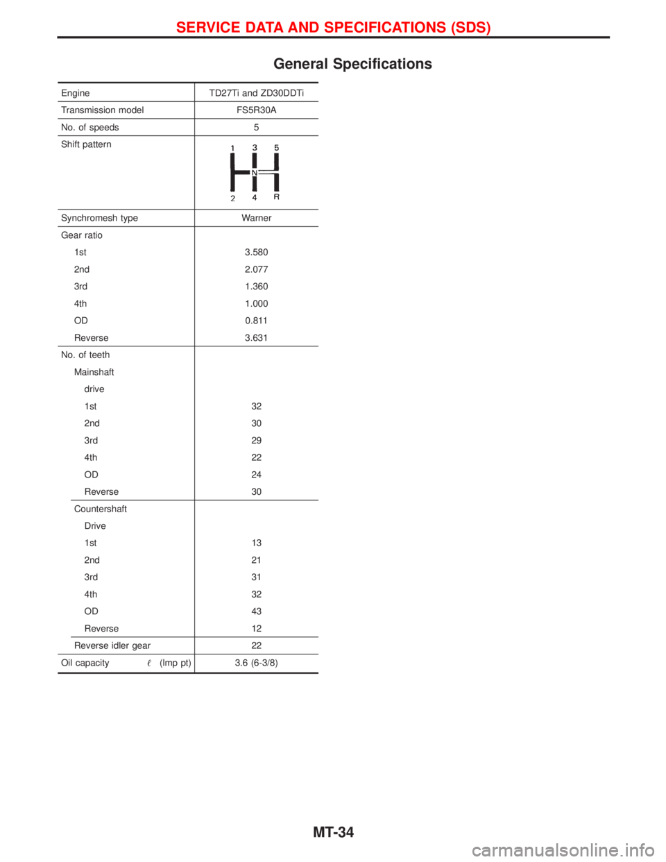
General Specifications
Engine TD27Ti and ZD30DDTi
Transmission model FS5R30A
No. of speeds 5
Shift pattern
Synchromesh type Warner
Gear ratio
1st 3.580
2nd 2.077
3rd 1.360
4th 1.000
OD 0.811
Reverse 3.631
No. of teeth
Mainshaft
drive
1st 32
2nd 30
3rd 29
4th 22
OD 24
Reverse 30
Countershaft
Drive
1st 13
2nd 21
3rd 31
4th 32
OD 43
Reverse 12
Reverse idler gear 22
Oil capacity(lmp pt) 3.6 (6-3/8)
SERVICE DATA AND SPECIFICATIONS (SDS)
MT-34
Page 1602 of 1767
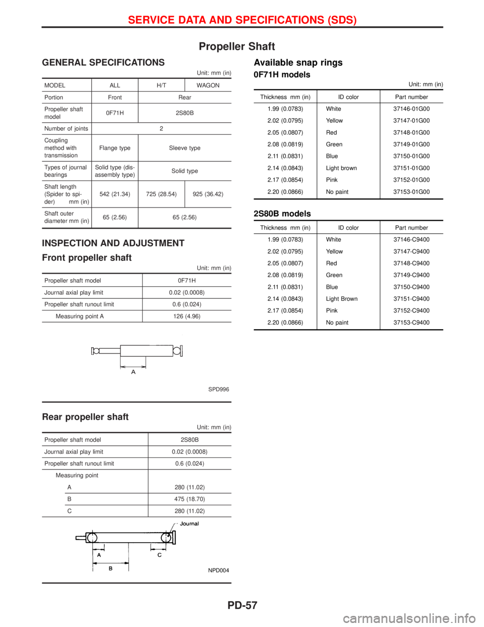
Propeller Shaft
GENERAL SPECIFICATIONS
Unit: mm (in)
MODEL ALL H/T WAGON
Portion Front Rear
Propeller shaft
model0F71H 2S80B
Number of joints 2
Coupling
method with
transmissionFlange type Sleeve type
Types of journal
bearingsSolid type (dis-
assembly type)Solid type
Shaft length
(Spider to spi-
der) mm (in)542 (21.34) 725 (28.54) 925 (36.42)
Shaft outer
diameter mm (in)65 (2.56) 65 (2.56)
INSPECTION AND ADJUSTMENT
Front propeller shaft
Unit: mm (in)
Propeller shaft model 0F71H
Journal axial play limit 0.02 (0.0008)
Propeller shaft runout limit 0.6 (0.024)
Measuring point A 126 (4.96)
SPD996
Rear propeller shaft
Unit: mm (in)
Propeller shaft model 2S80B
Journal axial play limit 0.02 (0.0008)
Propeller shaft runout limit 0.6 (0.024)
Measuring point
A 280 (11.02)
B 475 (18.70)
C 280 (11.02)
NPD004
Available snap rings
0F71H models
Unit: mm (in)
Thickness mm (in) ID color Part number
1.99 (0.0783) White 37146-01G00
2.02 (0.0795) Yellow 37147-01G00
2.05 (0.0807) Red 37148-01G00
2.08 (0.0819) Green 37149-01G00
2.11 (0.0831) Blue 37150-01G00
2.14 (0.0843) Light brown 37151-01G00
2.17 (0.0854) Pink 37152-01G00
2.20 (0.0866) No paint 37153-01G00
2S80B models
Thickness mm (in) ID color Part number
1.99 (0.0783) White 37146-C9400
2.02 (0.0795) Yellow 37147-C9400
2.05 (0.0807) Red 37148-C9400
2.08 (0.0819) Green 37149-C9400
2.11 (0.0831) Blue 37150-C9400
2.14 (0.0843) Light Brown 37151-C9400
2.17 (0.0854) Pink 37152-C9400
2.20 (0.0866) No paint 37153-C9400
SERVICE DATA AND SPECIFICATIONS (SDS)
PD-57
Page 1603 of 1767
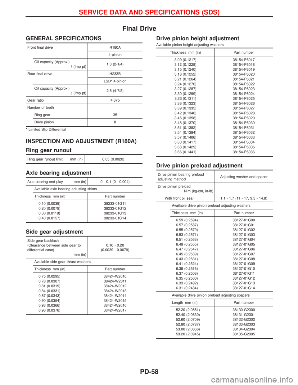
Final Drive
GENERAL SPECIFICATIONS
Front final drive R180A
4-pinion
Oil capacity (Approx.)
(Imp pt)1.3 (2-1/4)
Rear final drive H233B
LSD* 4-pinion
Oil capacity (Approx.)
(Imp pt)2.8 (4-7/8)
Gear ratio 4.375
Number of teeth
Ring gear 35
Drive pinion 8
* Limited Slip Differential
INSPECTION AND ADJUSTMENT (R180A)
Ring gear runout
Ring gear runout limit mm (in) 0.05 (0.0020)
Axle bearing adjustment
Axle bearing end play mm (in) 0 - 0.1 (0 - 0.004)
Available axle bearing adjusting shims
Thickness mm (in) Part number
0.10 (0.0039) 38233-01G11
0.20 (0.0079) 38233-01G12
0.30 (0.0118) 38233-01G13
0.40 (0.0157) 38233-01G14
Side gear adjustment
Side gear backlash
(Clearance between side gear to
differential case)
mm (in)0.10 - 0.20
(0.0039 - 0.0079)
Available side gear thrust washers
Thickness mm (in) Part number
0.75 (0.0295) 38424-W2010
0.78 (0.0307) 38424-W2011
0.81 (0.0319) 38424-W2012
0.84 (0.0331) 38424-W2013
0.87 (0.0343) 38424-W2014
0.90 (0.0354) 38424-W2015
0.93 (0.0366) 38424-W2016
0.96 (0.0378) 38424-W2017
Drive pinion height adjustment
Available pinion height adjusting washers
Thickness mm (in) Part number
3.09 (0.1217) 38154-P6017
3.12 (0.1228) 38154-P6018
3.15 (0.1240) 38154-P6019
3.18 (0.1252) 38154-P6020
3.21 (0.1264) 38154-P6021
3.24 (0.1276) 38154-P6022
3.27 (0.1287) 38154-P6023
3.30 (0.1299) 38154-P6024
3.33 (0.1311) 38154-P6025
3.36 (0.1323) 38154-P6026
3.39 (0.1335) 38154-P6027
3.42 (0.1346) 38154-P6028
3.45 (0.1358) 38154-P6029
3.48 (0.1370) 38154-P6030
3.51 (0.1382) 38154-P6031
3.54 (0.1394) 38154-P6032
3.57 (0.1406) 38154-P6033
3.60 (0.1417) 38154-P6034
3.63 (0.1429) 38154-P6035
3.66 (0.1441) 38154-P6036
Drive pinion preload adjustment
Drive pinion bearing preload
adjusting methodAdjusting washer and spacer
Drive pinion preload
N×m (kg-cm, in-lb)
With front oil seal 1.1 - 1.7 (11 - 17, 9.5 - 14.8)
Available drive pinion preload adjusting washers
Thickness mm (in) Part number
6.59 (0.2594) 38127-01G00
6.57 (0.2587) 38127-01G01
6.55 (0.2579) 38127-01G02
6.53 (0.2571) 38127-01G03
6.51 (0.2563) 38127-01G04
6.49 (0.2555) 38127-01G05
6.47 (0.2547) 38127-01G06
6.45 (0.2539) 38127-01G07
6.43 (0.2531) 38127-01G08
6.41 (0.2524) 38127-01G09
6.39 (0.2516) 38127-01G10
6.37 (0.2508) 38127-01G11
6.35 (0.2500) 38127-01G12
6.33 (0.2492) 38127-01G13
6.31 (0.2484) 38127-01G14
Available drive pinion preload adjusting spacers
Length mm (in) Part number
52.20 (2.0551) 38130-G2300
52.40 (2.0630) 38131-G2301
52.60 (2.0709) 38132-G2302
52.80 (2.0787) 38133-G2303
53.00 (2.0866) 38134-G2304
53.20 (2.0945) 38135-G2305
SERVICE DATA AND SPECIFICATIONS (SDS)
PD-58
Page 1606 of 1767
REAR AXLE &
REAR SUSPENSION
SECTION
RA
CONTENTS
PRECAUTIONS AND PREPARATION............................2
Precautions ..................................................................2
Preparation ..................................................................2
REAR AXLE AND REAR SUSPENSION........................4
CHECK AND ADJUSTMENT..........................................5
Rear Axle and Rear Suspension Parts .......................5
Rear Wheel Bearing ....................................................5
REAR AXLE.....................................................................6
Components.................................................................6
Removal .......................................................................7
Inspection.....................................................................8Installation ....................................................................9
REAR AXLE AND REAR SUSPENSION......................12
Removal and Installation ...........................................12
REAR SUSPENSION.....................................................13
Components...............................................................13
Coil Spring Shock Absorber ......................................14
Upper Link, Lower Link and Panhard Rod ................14
Stabilizer Bar .............................................................15
SERVICE DATA AND SPECIFICATIONS (SDS)..........16
General Specifications ...............................................16
Inspection and Adjustment ........................................16
Page 1621 of 1767
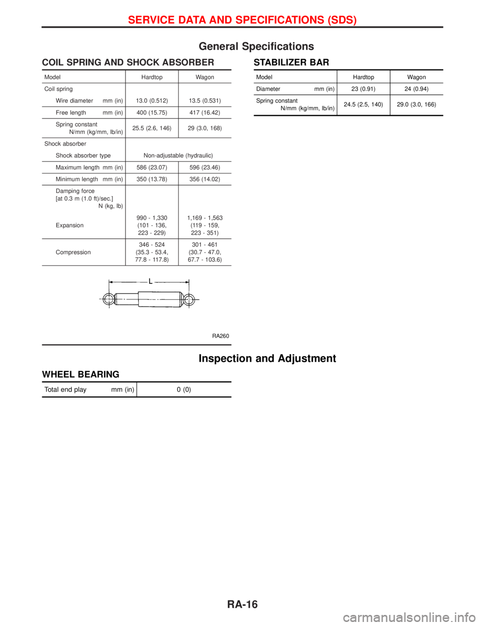
General Specifications
COIL SPRING AND SHOCK ABSORBER
Model Hardtop Wagon
Coil spring
Wire diameter mm (in) 13.0 (0.512) 13.5 (0.531)
Free length mm (in) 400 (15.75) 417 (16.42)
Spring constant
N/mm (kg/mm, lb/in)25.5 (2.6, 146) 29 (3.0, 168)
Shock absorber
Shock absorber type Non-adjustable (hydraulic)
Maximum length mm (in) 586 (23.07) 596 (23.46)
Minimum length mm (in) 350 (13.78) 356 (14.02)
Damping force
[at 0.3 m (1.0 ft)/sec.]
N (kg, lb)
Expansion990 - 1,330
(101 - 136,
223 - 229)1,169 - 1,563
(119 - 159,
223 - 351)
Compression346 - 524
(35.3 - 53.4,
77.8 - 117.8)301 - 461
(30.7 - 47.0,
67.7 - 103.6)
RA260
STABILIZER BAR
Model Hardtop Wagon
Diameter mm (in) 23 (0.91) 24 (0.94)
Spring constant
N/mm (kg/mm, lb/in)24.5 (2.5, 140) 29.0 (3.0, 166)
Inspection and Adjustment
WHEEL BEARING
Total end play mm (in) 0 (0)
SERVICE DATA AND SPECIFICATIONS (SDS)
RA-16
Page 1650 of 1767
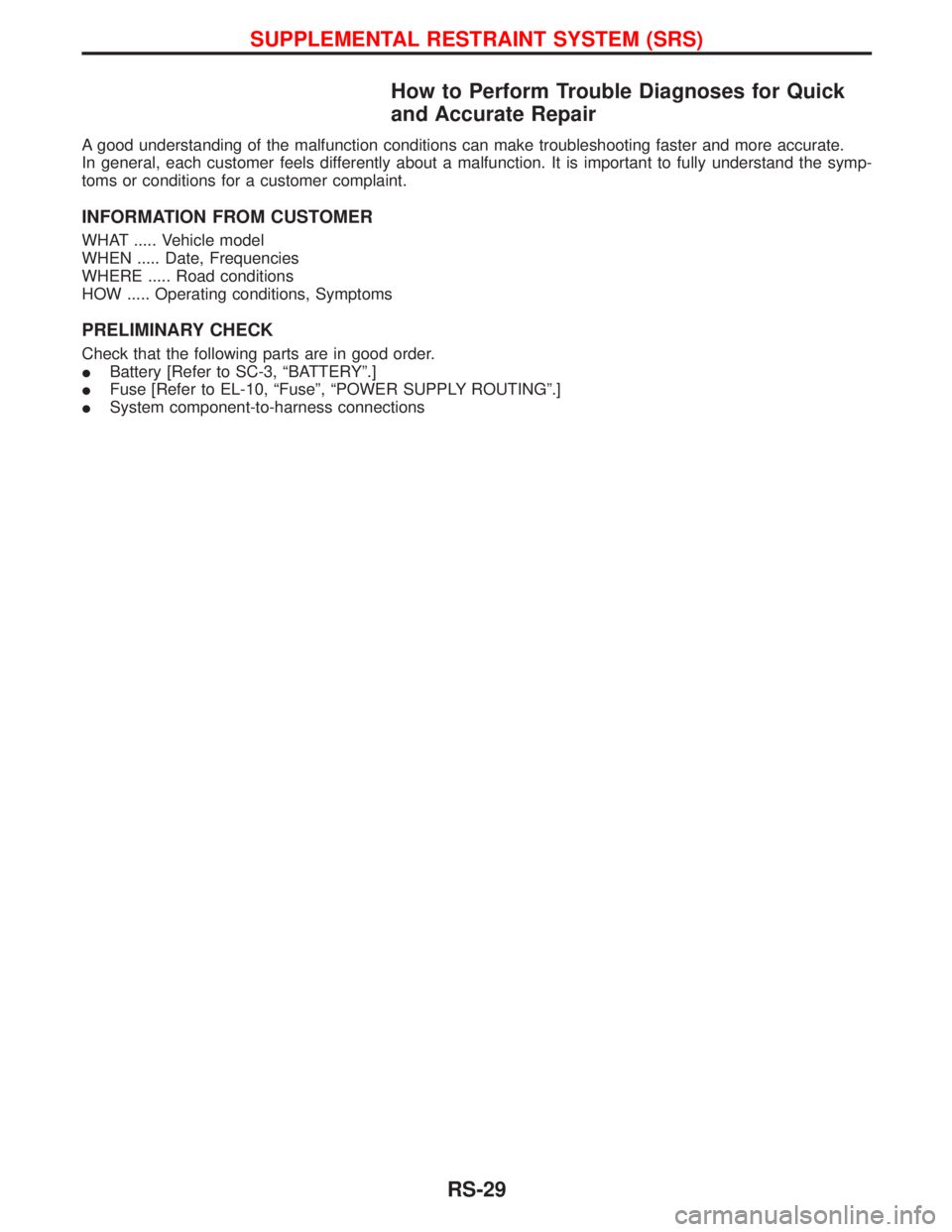
How to Perform Trouble Diagnoses for Quick
and Accurate Repair
A good understanding of the malfunction conditions can make troubleshooting faster and more accurate.
In general, each customer feels differently about a malfunction. It is important to fully understand the symp-
toms or conditions for a customer complaint.
INFORMATION FROM CUSTOMER
WHAT ..... Vehicle model
WHEN ..... Date, Frequencies
WHERE ..... Road conditions
HOW ..... Operating conditions, Symptoms
PRELIMINARY CHECK
Check that the following parts are in good order.
IBattery [Refer to SC-3, ªBATTERYº.]
IFuse [Refer to EL-10, ªFuseº, ªPOWER SUPPLY ROUTINGº.]
ISystem component-to-harness connections
SUPPLEMENTAL RESTRAINT SYSTEM (SRS)
RS-29
Page 1712 of 1767
STEERING SYSTEM
SECTION
ST
CONTENTS
PRECAUTIONS...............................................................2
Supplemental Restraint System (SRS)²AIR
BAG²and²SEAT BELT PRE-TENSIONER²
(Dual Air Bag System) .................................................2
Precautions for Steering System .................................2
PREPARATION................................................................3
Special Service Tools ..................................................3
ON-VEHICLE SERVICE..................................................4
Checking Steering Wheel Play ....................................4
Checking Neutral Position on Steering Wheel ............4
Front Wheel Turning Angle ..........................................4
Checking and Adjusting Drive Belts ............................4
Checking Fluid Level ...................................................4
Checking Fluid Leakage ..............................................5
Bleeding Hydraulic System..........................................5
Checking Steering Wheel Turning Force ....................6
Checking Hydraulic System.........................................7STEERING WHEEL AND STEERING COLUMN............8
Removal and Installation .............................................8
Disassembly and Assembly .......................................10
Inspection................................................................... 11
POWER STEERING GEAR...........................................12
Description .................................................................12
Removal and Installation ...........................................14
Inspection and Adjustment ........................................15
POWER STEERING OIL PUMP....................................16
Removal and Installation ...........................................16
STEERING LINKAGE....................................................17
Removal and Installation ...........................................17
Disassembly and Assembly .......................................19
Inspection...................................................................20
SERVICE DATA AND SPECIFICATIONS (SDS)..........22
General Specifications ...............................................22
Inspection and Adjustment ........................................22