Page 1236 of 1767
PISTON RING SIDE CLEARANCE
Side clearance:
Top ring
0.00 - 0.05 mm (0.0 - 0.0020 in)
2nd ring
0.04 - 0.072 mm (0.0016 - 0.0028 in)
Oil ring
0.035 - 0.040 mm (0.0014 - 0.0016 in)
Max. limit of side clearance:
Top ring
0.5 mm (0.020 in)
2nd ring
0.3 mm (0.012 in)
Oil ring
0.15 mm (0.0059 in)
PISTON RING END GAP
Standard ring gap:
Top ring
0.25 - 0.35 mm (0.0098 - 0.0138 in)
2nd ring
0.50 - 0.75 mm (0.0197 - 0.0295 in)
Oil ring
0.25 - 0.55 mm (0.0098 - 0.0217 in)
Max. limit of ring gap:
1.5 mm (0.059 in)
BEARING CLEARANCE
Main bearing
1. Install main bearings to cylinder block and main bearing cap.
2. Install main bearing cap to cylinder block.
Tighten all bolts in correct order and in two or three stages.
3. Measure inside diameter ªAº of main bearing.
4. Measure outside diameter ªDmº of main journal in crankshaft.
EEM117
SEM905
YEM044
YEM045
ENGINE OVERHAULTD27Ti
Inspection (Cont'd)
EM-128
Page 1237 of 1767
5. Calculate main bearing clearance.
Main bearing clearance = A þ Dm
Standard
0.035 - 0.087 mm (0.0014 - 0.0034 in)
Limit
Less than 0.15 mm (0.0059 in)
CONNECTING ROD BEARING (Big end)
1. Install connecting rod bearing to connecting rod and cap.
2. Install connecting rod cap to connecting rod.
Apply oil to the thread portion of bolts and seating surface of
nuts.
3. Measure inside diameter ªAº of bearing.
4. Measure outside diameter ªDpº of pin journal in crankshaft.
5. Calculate connecting rod bearing clearance.
Connecting rod bearing clearance = A þ Dp
Standard
0.035 - 0.081 mm
(0.0014 - 0.0032 in)
Limit
Less than 0.15 mm (0.0059 in)
CONNECTING ROD BEND AND TORSION
Bend and torsion:
Limit
0.15 mm (0.0059 in)
per 200 mm (7.87 in) length
CONNECTING ROD BUSHING CLEARANCE (Small end)
1. Measure inside diameter ªAº of connecting rod small end bush-
ings.
YEM046
EM133
YEM047
ENGINE OVERHAULTD27Ti
Inspection (Cont'd)
EM-129
Page 1238 of 1767

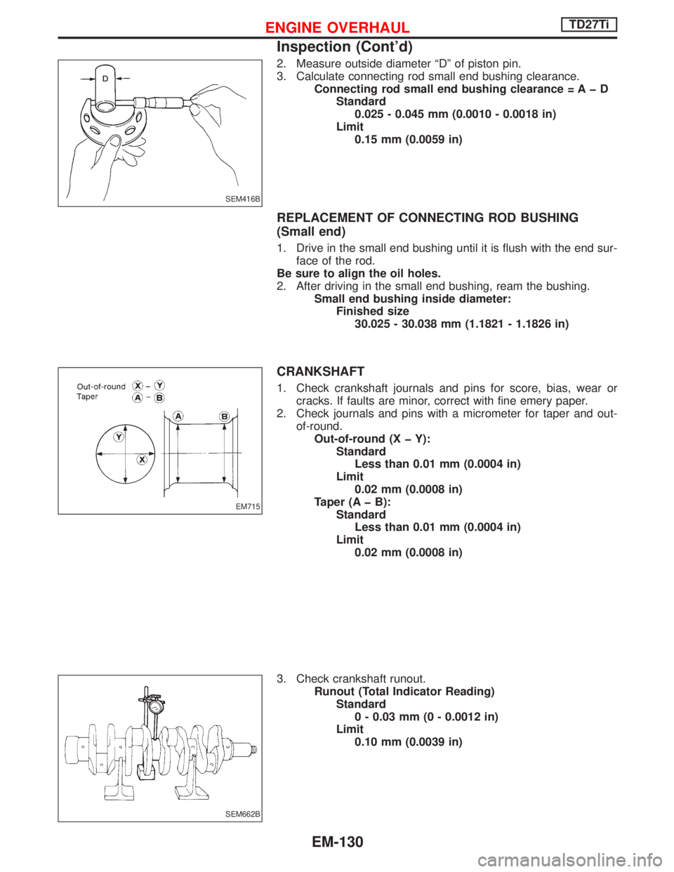
2. Measure outside diameter ªDº of piston pin.
3. Calculate connecting rod small end bushing clearance.
Connecting rod small end bushing clearance = A þ D
Standard
0.025 - 0.045 mm (0.0010 - 0.0018 in)
Limit
0.15 mm (0.0059 in)
REPLACEMENT OF CONNECTING ROD BUSHING
(Small end)
1. Drive in the small end bushing until it is flush with the end sur-
face of the rod.
Be sure to align the oil holes.
2. After driving in the small end bushing, ream the bushing.
Small end bushing inside diameter:
Finished size
30.025 - 30.038 mm (1.1821 - 1.1826 in)
CRANKSHAFT
1. Check crankshaft journals and pins for score, bias, wear or
cracks. If faults are minor, correct with fine emery paper.
2. Check journals and pins with a micrometer for taper and out-
of-round.
Out-of-round (X þ Y):
Standard
Less than 0.01 mm (0.0004 in)
Limit
0.02 mm (0.0008 in)
Taper (A þ B):
Standard
Less than 0.01 mm (0.0004 in)
Limit
0.02 mm (0.0008 in)
3. Check crankshaft runout.
Runout (Total Indicator Reading)
Standard
0 - 0.03 mm (0 - 0.0012 in)
Limit
0.10 mm (0.0039 in)
SEM416B
EM715
SEM662B
ENGINE OVERHAULTD27Ti
Inspection (Cont'd)
EM-130
Page 1240 of 1767
GEAR TRAIN
Camshaft drive gear, injection pump drive gear, oil pump gear,
idler gear, crankshaft gear and vacuum pump gear.
1. If gear tooth and key have scratches or are excessively worn,
replace gear and key.
2. Check gear train backlash before disassembling and after
assembling.
Method A (Using dial gauge)
Method B (Using fuse wire)
If beyond the limit, replace gear.
Backlash:
Standard
0.07 - 0.11 mm (0.0028 - 0.0043 in)
Limit
0.20 mm (0.0079 in)
IDLER GEAR BUSHING CLEARANCE
1. Measure idler gear shaft outer diameter.
2. Measure idler gear bushing inner diameter.
3. Calculate idler gear bushing clearance.
Bushing oil clearance:
Standard
0.025 - 0.061 mm (0.0010 - 0.0024 in)
Limit
0.20 mm (0.0079 in)
IDLER GEAR END PLAY
Measure idler gear end play between gear plate and gear.
Idler gear end play:
Standard
0.03 - 0.14 mm (0.0012 - 0.0055 in)
Limit
Less than 0.3 mm (0.012 in)
NEM186
NEM187
SEM666B
SEM705
ENGINE OVERHAULTD27Ti
Inspection (Cont'd)
EM-132
Page 1241 of 1767

REPLACEMENT OF IDLER GEAR BUSHING
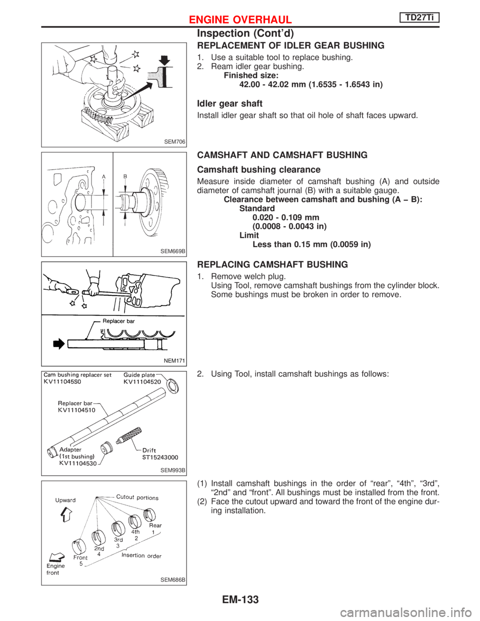
1. Use a suitable tool to replace bushing.
2. Ream idler gear bushing.
Finished size:
42.00 - 42.02 mm (1.6535 - 1.6543 in)
Idler gear shaft
Install idler gear shaft so that oil hole of shaft faces upward.
CAMSHAFT AND CAMSHAFT BUSHING
Camshaft bushing clearance
Measure inside diameter of camshaft bushing (A) and outside
diameter of camshaft journal (B) with a suitable gauge.
Clearance between camshaft and bushing (A þ B):
Standard
0.020 - 0.109 mm
(0.0008 - 0.0043 in)
Limit
Less than 0.15 mm (0.0059 in)
REPLACING CAMSHAFT BUSHING
1. Remove welch plug.
Using Tool, remove camshaft bushings from the cylinder block.
Some bushings must be broken in order to remove.
2. Using Tool, install camshaft bushings as follows:
(1) Install camshaft bushings in the order of ªrearº, ª4thº, ª3rdº,
ª2ndº and ªfrontº. All bushings must be installed from the front.
(2) Face the cutout upward and toward the front of the engine dur-
ing installation.
SEM706
SEM669B
NEM171
SEM993B
SEM686B
ENGINE OVERHAULTD27Ti
Inspection (Cont'd)
EM-133
Page 1242 of 1767
(3) Rear camshaft bushing.
Align the cutout of rear bushing with knock pin of replacer bar
before installation.
Insert rear bushing with replacer bar into the cylinder block.
Install guide plate with bolt holes (on the ªTDº mark side) fac-
ing upper side of cylinder block. Tighten bolts.
Drive replacer bar until the alignment mark on replacer bar is
aligned with the end of replacer guide.
Remove replacer set.
After installation, check that oil hole in camshaft bushing are
aligned with oil hole in cylinder block.
SEM995B
SEM110C
NEM172
ENGINE OVERHAULTD27Ti
Inspection (Cont'd)
EM-134
Page 1243 of 1767
(4) 4th, 3rd and 2nd camshaft bushings.
Install in the same manner as rear camshaft bushing.
(5) Front camshaft bushing.
Using 1st bushing adapter, position front camshaft bushing so
that oil hole in cylinder block is aligned with oil hole in bushing.
The camshaft bushing of the front side must be inserted at 0.5
mm (0.020 in) from the extreme front of cylinder block.
NEM173
SEM001C
EEM105
ENGINE OVERHAULTD27Ti
Inspection (Cont'd)
EM-135
Page 1246 of 1767

Assembly
PISTON
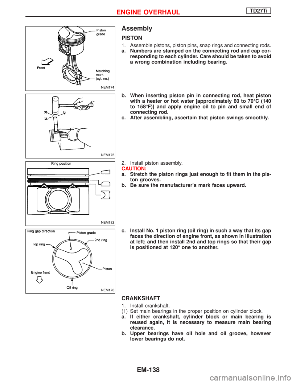
1. Assemble pistons, piston pins, snap rings and connecting rods.
a. Numbers are stamped on the connecting rod and cap cor-
responding to each cylinder. Care should be taken to avoid
a wrong combination including bearing.
b. When inserting piston pin in connecting rod, heat piston
with a heater or hot water [approximately 60 to 70ÉC (140
to 158ÉF)] and apply engine oil to pin and small end of
connecting rod.
c. After assembling, ascertain that piston swings smoothly.
2. Install piston assembly.
CAUTION:
a. Stretch the piston rings just enough to fit them in the pis-
ton grooves.
b. Be sure the manufacturer's mark faces upward.
c. Install No. 1 piston ring (oil ring) in such a way that its gap
faces the direction of engine front, as shown in illustration
at left; and then install 2nd and top rings so that their gap
is positioned at 120É one to another.
CRANKSHAFT
1. Install crankshaft.
(1) Set main bearings in the proper position on cylinder block.
a. If either crankshaft, cylinder block or main bearing is
reused again, it is necessary to measure main bearing
clearance.
b. Upper bearings have oil hole and oil groove, however
lower bearings do not.
NEM174
NEM175
NEM182
NEM176
ENGINE OVERHAULTD27Ti
EM-138