Page 1247 of 1767
(2) Apply engine oil to crankshaft journal and pin and install crank-
shaft.
(3) Install main bearings caps.
a) Install main bearing cap with the lowest number facing the front
of vehicle.
b) Apply engine oil to main bearing cap and cylinder block contact
surfaces.
c) Install rear oil seal assembly. Apply engine oil to contact surface
of rear end oil seal and crankshaft.
(4) Install crankshaft thrust washer at the 4th journal from front.
Install thrust washer so that oil groove can face crankshaft.
(5) Tighten bearing cap bolts gradually in stages, starting from two
to three separate stages, from center bearing and moving out-
ward in sequence.
(6) Measure crankshaft free end play at No. 4 bearing.
Crankshaft free end play:
Standard
0.060 - 0.25 mm (0.002 - 0.01 in)
Limit
0.4 mm (0.016 in)
If beyond the limit, replace No. 4 main bearing thrust washer.
Refer to SDS.
SEM674B
SEM057
SEM675B
SEM677B
SEM063
ENGINE OVERHAULTD27Ti
Assembly (Cont'd)
EM-139
Page 1248 of 1767
2. Install pistons with connecting rods.
(1) Install them into corresponding cylinder using Tool.
IBe careful not to scratch cylinder wall with connecting rod.
IApply engine oil to cylinder wall, piston and bearing.
IThe leaf type combustion chamber on piston head must be
facing toward the fuel pump side.
(2) Install connecting rod bearing caps.
3. Measure connecting rod side clearance.
Connecting rod side clearance:
Standard
0.10 - 0.22 mm (0.0039 - 0.0087 in)
Limit
0.22 mm (0.0087 in)
If beyond the limit, replace connecting rod and/or crankshaft.
4. Install oil strainer and oil pan.
5. Install all removed parts.
GEAR TRAIN
1. Set No. 1 piston at its Top Dead Center.
2. Align each gear mark and install gears.
EEM108
SEM678B
SEM488
NEM177
ENGINE OVERHAULTD27Ti
Assembly (Cont'd)
EM-140
Page 1251 of 1767
General Specifications
Engine model TD27Ti
Cylinder arrangement 4, in-line
Displacement cm
3(cu in) 2,663 (162.5)
Bore x stroke mm (in) 96 x 92 (3.8 x 3.6)
Valve arrangement OHV
Firing order 1-3-4-2
Number of piston rings
Compression 2
Oil 1
Number of main bearings 5
Compression ratio 21.9 0.2
Unit: kPa (bar, kg/cm
2, psi)/rpm
Compression pressure
Standard 2,942 (29.4, 30, 427)/200
Minimum 2,452 (24.5, 25, 356)/200
Differential limit between
cylinders294 (2.9, 3, 43)/200
SERVICE DATA AND SPECIFICATIONS (SDS)TD27Ti
EM-143
Page 1260 of 1767
(1) When installing each rubber part, final tightening must be car-
ried out under unladen condition * with tires on ground.
* Fuel, radiator coolant and engine oil full. Spare tire, jack,
hand tools and mats in designated positions.
(2) When removing each suspension part, check wheel alignment
and adjust if necessary.
(3) Use Tool when removing or installing brake tubes.
SBR820B
PRECAUTIONS
FA-2
Page 1297 of 1767

Inspection and Adjustment
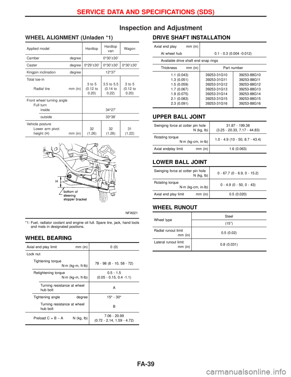
WHEEL ALIGNMENT (Unladen *1)
Applied model HardtopHardtop
vanWagon
Camber degree 0É30¢ 30¢
Caster degree 0É29¢ 30¢0É30¢ 30¢0É30¢ 30¢
Kingpin inclination degree 12É37¢
Total toe-in
Radial tire mm (in)3to5
(0.12 to
0.20)3.5 to 5.5
(0.14 to
0.22)3to5
(0.12 to
0.20)
Front wheel turning angle
Full turn
inside 34É27¢
outside 33É38¢
Vehicle posture
Lower arm pivot
height (H) mm (in)32
(1.26)32
(1.26)31
(1.22)
NFA021
*1: Fuel, radiator coolant and engine oil full. Spare tire, jack, hand tools
and mats in designated positions.
WHEEL BEARING
Axial end play limit mm (in) 0 (0)
Lock nut
Tightening torque
N×m (kg-m, ft-lb)78-98(8-10,58-72)
Retightening torque
N×m (kg-m, ft-lb)0.5 - 1.5
(0.05 - 0.15, 0.4 -1.1)
Turning resistance at wheel
hub boltA
Tightening angle degree 15É - 30É
Turning resistance at wheel
hub boltB
PreloadC=BþA N(kg, lb)7.06 - 20.99
(0.72 - 2.14, 1.59 - 4.72)
DRIVE SHAFT INSTALLATION
Axial end play mm (in)
At wheel hub 0.1 - 0.3 (0.004 -0.012)
Available drive shaft end snap rings
Thickness mm (in) Part number
1.1 (0.043) 39253-31G10 39253-88G10
1.3 (0.051) 39253-31G11 39253-88G11
1.5 (0.059) 39253-31G12 39253-88G12
1.7 (0.067) 39253-31G13 39253-88G13
1.9 (0.075) 39253-31G14 39253-88G14
2.1 (0.083) 39253-31G15 39253-88G15
2.3 (0.091) 39253-31G16 39253-88G16
UPPER BALL JOINT
Swinging force at cotter pin hole
N (kg, lb)31.87 - 199.38
(3.25 - 20.33, 7.17 - 44.83)
Rotating torque
N×m (kg-cm, in-lb)1.0 - 4.9 (10 - 50, 8.7 - 43.4)
Axial endplay limit mm (in) 1.6 (0.063)
LOWER BALL JOINT
Swinging force at cotter pin hole
N (kg, lb)0 - 67.7 (0 - 6.9, 0 - 15.2)
Rotating torque
N×m (kg-cm, in-lb)0 - 4.9 (0 - 50, 0 - 43)
Axial end play limit mm (in) 0.5 (0.020)
WHEEL RUNOUT
Wheel typeSteel
(15²)
Radial runout limit
mm (in)0.5 (0.02)
Lateral runout limit
mm (in)0.8 (0.031)
SERVICE DATA AND SPECIFICATIONS (SDS)
FA-39
Page 1308 of 1767
CAUTION:
IBe careful not to drop or damage catalytic converter.
INever wet catalytic converter with water, oil, etc.
IAlways replace exhaust gaskets with new ones when reas-
sembling.
If gasket is left on flange surface, scrape off complete as
shown at left.
IWith engine running, check all tube connections for
exhaust gas leaks, and entire system for unusual noises.
IAfter installation, but before fully tightening exhaust joints,
check to ensure that mounting brackets and mounting
insulators are free from undue stress. If any of the above
parts are not installed properly, excessive noise or vibra-
tion may be transmitted to the vehicle body.
SFE180A
EXHAUST SYSTEMTD27Ti
FE-10
Page 1316 of 1767

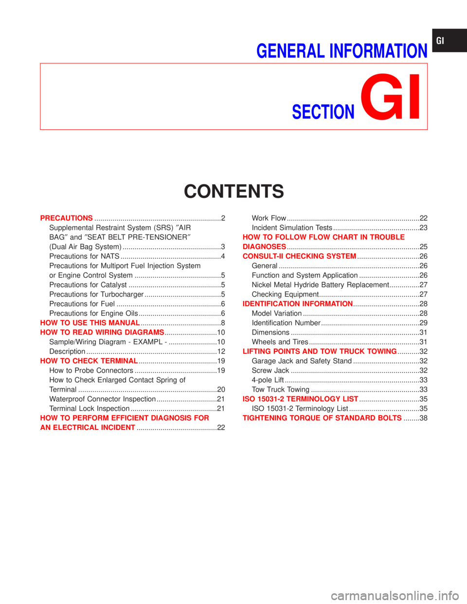
GENERAL INFORMATION
SECTION
GI
CONTENTS
PRECAUTIONS...............................................................2
Supplemental Restraint System (SRS)²AIR
BAG²and²SEAT BELT PRE-TENSIONER²
(Dual Air Bag System) .................................................3
Precautions for NATS ..................................................4
Precautions for Multiport Fuel Injection System
or Engine Control System ...........................................5
Precautions for Catalyst ..............................................5
Precautions for Turbocharger ......................................5
Precautions for Fuel ....................................................6
Precautions for Engine Oils .........................................6
HOW TO USE THIS MANUAL........................................8
HOW TO READ WIRING DIAGRAMS..........................10
Sample/Wiring Diagram - EXAMPL - ........................10
Description .................................................................12
HOW TO CHECK TERMINAL.......................................19
How to Probe Connectors .........................................19
How to Check Enlarged Contact Spring of
Terminal .....................................................................20
Waterproof Connector Inspection ..............................21
Terminal Lock Inspection ...........................................21
HOW TO PERFORM EFFICIENT DIAGNOSIS FOR
AN ELECTRICAL INCIDENT........................................22Work Flow ..................................................................22
Incident Simulation Tests ...........................................23
HOW TO FOLLOW FLOW CHART IN TROUBLE
DIAGNOSES..................................................................25
CONSULT-II CHECKING SYSTEM...............................26
General ......................................................................26
Function and System Application ..............................26
Nickel Metal Hydride Battery Replacement...............27
Checking Equipment..................................................27
IDENTIFICATION INFORMATION.................................28
Model Variation ..........................................................28
Identification Number .................................................29
Dimensions ................................................................31
Wheels and Tires .......................................................31
LIFTING POINTS AND TOW TRUCK TOWING...........32
Garage Jack and Safety Stand .................................32
Screw Jack ................................................................32
4-pole Lift ...................................................................33
Tow Truck Towing ......................................................33
ISO 15031-2 TERMINOLOGY LIST..............................35
ISO 15031-2 Terminology List ...................................35
TIGHTENING TORQUE OF STANDARD BOLTS........38
Page 1320 of 1767

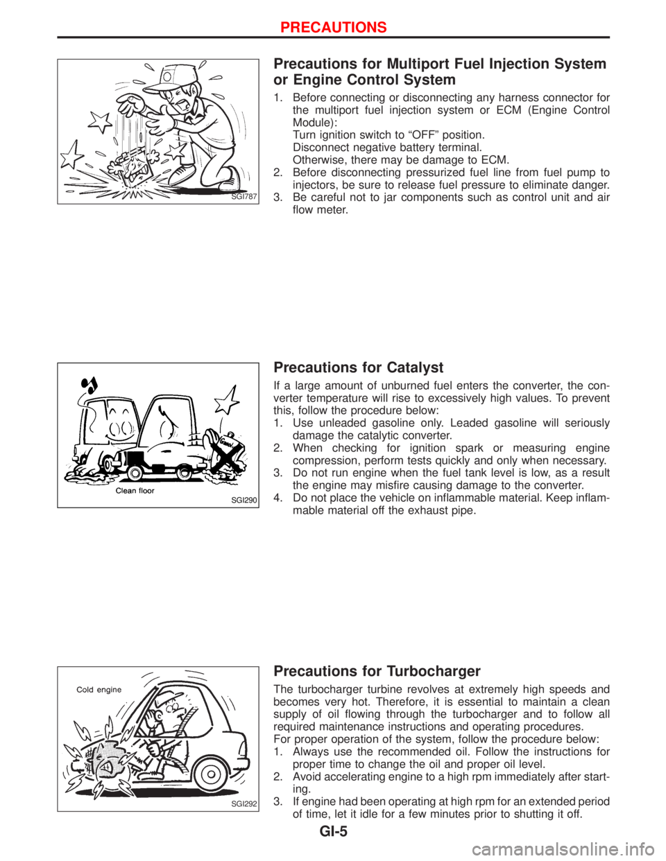
Precautions for Multiport Fuel Injection System
or Engine Control System
1. Before connecting or disconnecting any harness connector for
the multiport fuel injection system or ECM (Engine Control
Module):
Turn ignition switch to ªOFFº position.
Disconnect negative battery terminal.
Otherwise, there may be damage to ECM.
2. Before disconnecting pressurized fuel line from fuel pump to
injectors, be sure to release fuel pressure to eliminate danger.
3. Be careful not to jar components such as control unit and air
flow meter.
Precautions for Catalyst
If a large amount of unburned fuel enters the converter, the con-
verter temperature will rise to excessively high values. To prevent
this, follow the procedure below:
1. Use unleaded gasoline only. Leaded gasoline will seriously
damage the catalytic converter.
2. When checking for ignition spark or measuring engine
compression, perform tests quickly and only when necessary.
3. Do not run engine when the fuel tank level is low, as a result
the engine may misfire causing damage to the converter.
4. Do not place the vehicle on inflammable material. Keep inflam-
mable material off the exhaust pipe.
Precautions for Turbocharger
The turbocharger turbine revolves at extremely high speeds and
becomes very hot. Therefore, it is essential to maintain a clean
supply of oil flowing through the turbocharger and to follow all
required maintenance instructions and operating procedures.
For proper operation of the system, follow the procedure below:
1. Always use the recommended oil. Follow the instructions for
proper time to change the oil and proper oil level.
2. Avoid accelerating engine to a high rpm immediately after start-
ing.
3. If engine had been operating at high rpm for an extended period
of time, let it idle for a few minutes prior to shutting it off.
SGI787
SGI290
SGI292
PRECAUTIONS
GI-5