Page 1213 of 1767

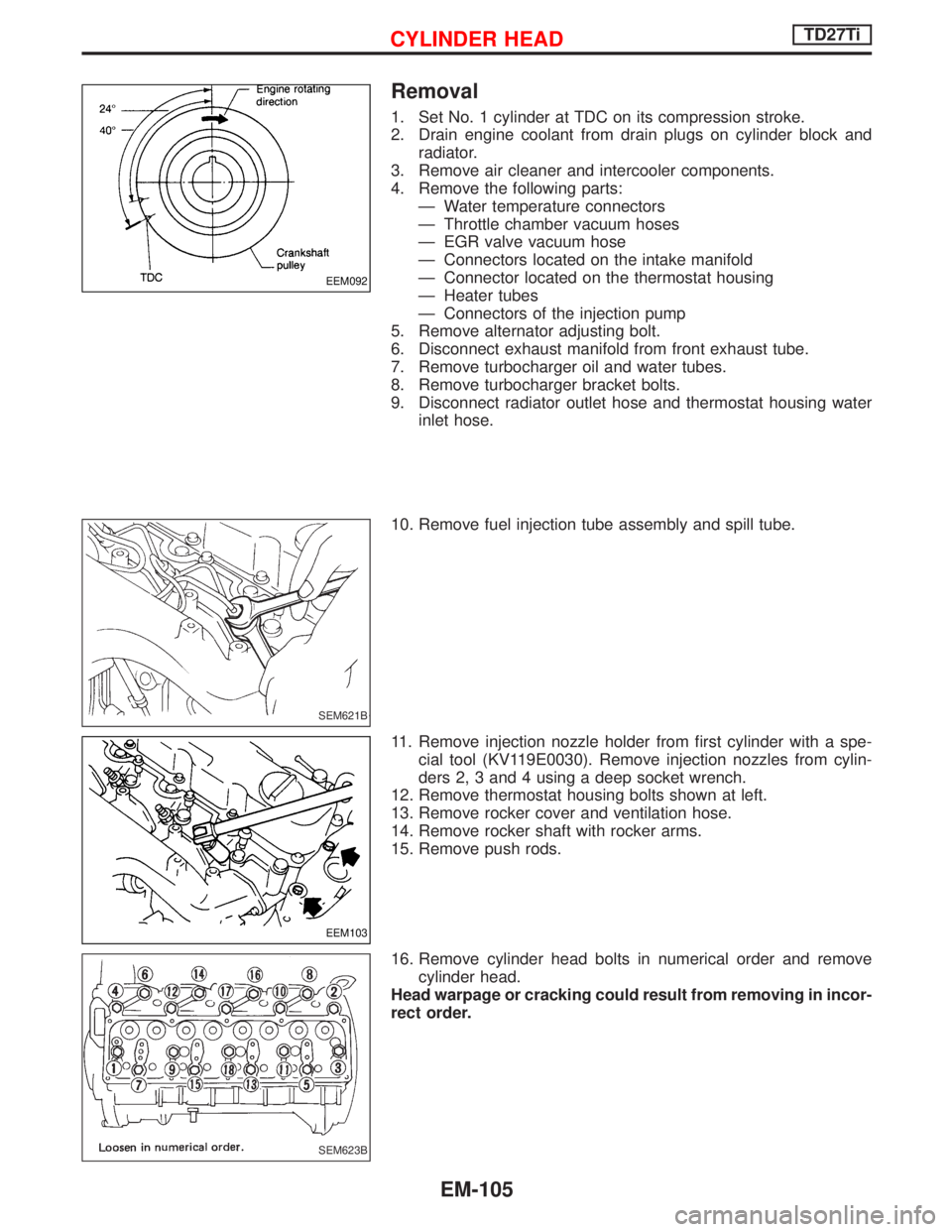
Removal
1. Set No. 1 cylinder at TDC on its compression stroke.
2. Drain engine coolant from drain plugs on cylinder block and
radiator.
3. Remove air cleaner and intercooler components.
4. Remove the following parts:
Ð Water temperature connectors
Ð Throttle chamber vacuum hoses
Ð EGR valve vacuum hose
Ð Connectors located on the intake manifold
Ð Connector located on the thermostat housing
Ð Heater tubes
Ð Connectors of the injection pump
5. Remove alternator adjusting bolt.
6. Disconnect exhaust manifold from front exhaust tube.
7. Remove turbocharger oil and water tubes.
8. Remove turbocharger bracket bolts.
9. Disconnect radiator outlet hose and thermostat housing water
inlet hose.
10. Remove fuel injection tube assembly and spill tube.
11. Remove injection nozzle holder from first cylinder with a spe-
cial tool (KV119E0030). Remove injection nozzles from cylin-
ders 2, 3 and 4 using a deep socket wrench.
12. Remove thermostat housing bolts shown at left.
13. Remove rocker cover and ventilation hose.
14. Remove rocker shaft with rocker arms.
15. Remove push rods.
16. Remove cylinder head bolts in numerical order and remove
cylinder head.
Head warpage or cracking could result from removing in incor-
rect order.
EEM092
SEM621B
EEM103
SEM623B
CYLINDER HEADTD27Ti
EM-105
Page 1214 of 1767
Disassembly
1. Remove following parts:
IEGR tube
IIntake manifold
IHeat shield plates
IExhaust manifold
IThermostat housing
IAlternator adjusting bar & engine slinger
IGlow plate and glow plugs
2. Remove valve component parts with Tool.
3. Remove valve oil seals with Tool.
4. Disassemble rocker shaft assembly.
a. Remove rocker shaft lock bolt.
b. Remove valve rocker and rocker shaft bracket.
If it is difficult to remove rocker shaft brackets, immerse rocker
shaft assembly in oil of 70ÉC (158ÉF) for a few minutes and
then remove brackets.
SEM624B
SEM625B
SEM626B
NEM160
CYLINDER HEADTD27Ti
EM-106
Page 1223 of 1767
2. Install cylinder head.
ICylinder head identification mark
3. Apply oil to threaded portion and seat surface of bolts and
tighten cylinder head bolts using Tool.
CAUTION:
ITightening procedure
1st: Tighten bolts to 39 - 44 N×m
(4.0 - 4.5 kg-m, 29 - 33 ft-lb)
2nd: Tighten bolts to 54 - 59 N×m
(5.5 - 6.0 kg-m, 40 - 43 ft-lb)
3rd:
(1) Mark exhaust side of cylinder head and cylin-
der head bolts with paint as shown.
(2) Turn all bolts 90 10 degrees clockwise.
(3) Check that paint mark of each bolt is facing
the front of the vehicle.
4. Apply engine oil and install push rods.
5. Install rocker shaft assembly.
Adjust intake and exhaust valve clearance carefully.
Refer to MA section in order to accomplish valve adjustment.
NEM179
SEM641B
SEM580C
SEM642B
CYLINDER HEADTD27Ti
Installation (Cont'd)
EM-115
Page 1225 of 1767
VALVE STEM OIL SEAL
1. Remove rocker cover.
2. Remove rocker shaft assembly.
3. Remove valve spring.
Piston concerned should be set at TDC to prevent valve from
falling.
4. Remove valve oil seals.
5. Apply engine oil to valve oil seal and install it in place.
SEM645B
SEM626B
SEM646B
SEM223B
OIL SEAL REPLACEMENTTD27Ti
EM-117
Page 1226 of 1767
OIL SEAL INSTALLING DIRECTION
IWhen installing a new front or rear oil seal, make sure its
mounting direction is correct.
CRANKSHAFT FRONT OIL SEAL
1. Remove protecting cover.
2. Remove radiator shroud.
3. Remove cooling fan.
4. Remove drive belts.
5. Remove crank pulley.
6. Remove crankshaft oil seal.
IBe careful not to damage sealing surfaces of crankshaft.
7. Coat new oil seal with engine oil and install it in place.
CRANKSHAFT REAR OIL SEAL
1. Dismount transmission.
2. Remove clutch cover assembly.
3. Remove flywheel and rear plate.
4. Remove oil seal retainer assembly, then remove oil seal.
IBe careful not to damage sealing surfaces of crankshaft.
5. Coat new oil seal with engine oil and install it in place.
SEM715A
SEM644B
SEM217B
OIL SEAL REPLACEMENTTD27Ti
EM-118
Page 1227 of 1767

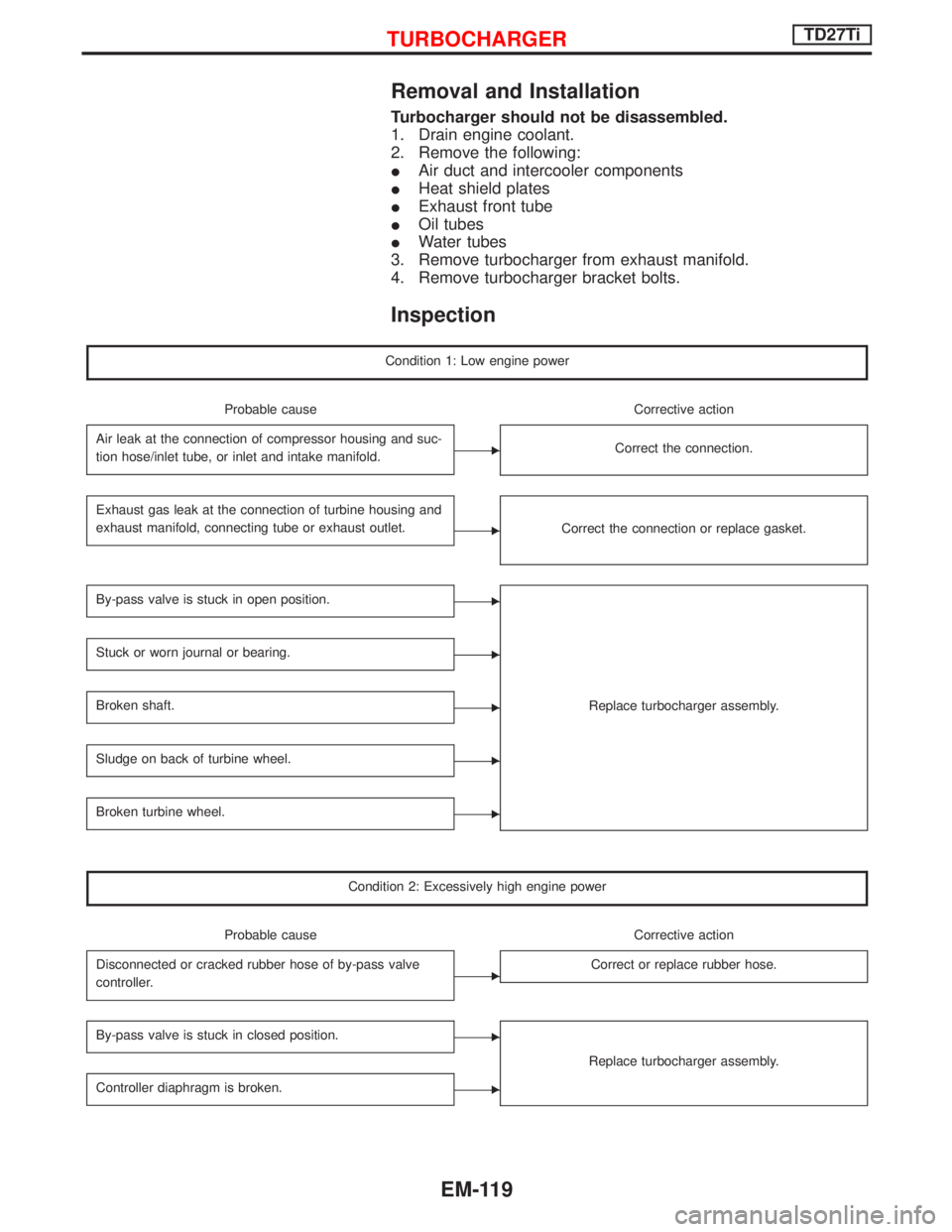
Removal and Installation
Turbocharger should not be disassembled.
1. Drain engine coolant.
2. Remove the following:
IAir duct and intercooler components
IHeat shield plates
IExhaust front tube
IOil tubes
IWater tubes
3. Remove turbocharger from exhaust manifold.
4. Remove turbocharger bracket bolts.
Inspection
Condition 1: Low engine power
Probable cause Corrective action
Air leak at the connection of compressor housing and suc-
tion hose/inlet tube, or inlet and intake manifold.
ECorrect the connection.
Exhaust gas leak at the connection of turbine housing and
exhaust manifold, connecting tube or exhaust outlet.
ECorrect the connection or replace gasket.
By-pass valve is stuck in open position.E
Replace turbocharger assembly.
Stuck or worn journal or bearing.E
Broken shaft.E
Sludge on back of turbine wheel.E
Broken turbine wheel.E
Condition 2: Excessively high engine power
Probable cause Corrective action
Disconnected or cracked rubber hose of by-pass valve
controller.
ECorrect or replace rubber hose.
By-pass valve is stuck in closed position.E
Replace turbocharger assembly.
Controller diaphragm is broken.E
TURBOCHARGERTD27Ti
EM-119
Page 1233 of 1767
Disassembly
PISTON AND CRANKSHAFT
1. Remove oil filter.
2. Place engine on work stand.
3. Drain coolant and oil.
4. Remove drive belts.
5. Remove cylinder head. Refer to ªCYLINDER HEADº.
6. Remove oil pan.
7. Remove crank pulley and timing gear plate cover.
8. Remove water pump.
9. Remove timing gear case.
If the timing case is hard to remove due to liquid gasket, pry
it off with a suitable tool at the cutout section.
10. Remove injection pump gear nut.
SEM650B
NEM165
NEM170
NEM166
NEM167
ENGINE OVERHAULTD27Ti
EM-125
Page 1234 of 1767
11. Remove injection pump gear.
12. Remove injection pump.
13. Remove idler gear and idler shaft.
14. Remove valve lifters, camshaft gear and camshaft.
15. Remove vacuum pump assembly.
16. Remove oil pump assembly.
17. Remove crankshaft gear.
18. Remove flywheel and rear plate.
19. Remove connecting rod caps.
20. Remove pistons.
21. Remove rear oil seal retainer.
22. Remove oil strainer.
SEM654B
NEM168
NEM169
SEM657B
ENGINE OVERHAULTD27Ti
Disassembly (Cont'd)
EM-126