Page 1189 of 1767

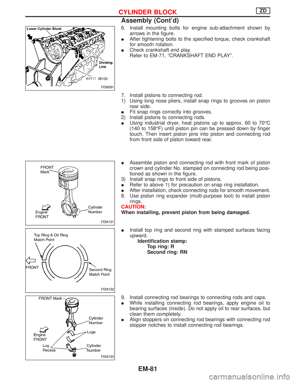
6. Install mounting bolts for engine sub-attachment shown by
arrows in the figure.
IAfter tightening bolts to the specified torque, check crankshaft
for smooth rotation.
ICheck crankshaft end play.
Refer to EM-71, ªCRANKSHAFT END PLAYº.
7. Install pistons to connecting rod.
1) Using long nose pliers, install snap rings to grooves on piston
rear side.
IFit snap rings correctly into grooves.
2) Install pistons to connecting rods.
IUsing industrial dryer, heat pistons up to approx. 60 to 70ÉC
(140 to 158ÉF) until piston pin can be pressed down by finger
touch. Then insert piston pins into piston and connecting rod
from front side of piston toward rear.
IAssemble piston and connecting rod with front mark of piston
crown and cylinder No. stamped on connecting rod being posi-
tioned as shown in the figure.
3) Install snap rings to front side of pistons.
IRefer to above 1) for precaution on snap ring installation.
IAfter installation, check connecting rods for smooth movement.
8. Use piston ring expander (multi-purpose tool) to install piston
rings.
CAUTION:
When installing, prevent piston from being damaged.
IInstall top ring and second ring with stamped surfaces facing
upward.
Identification stamp:
Top ring: R
Second ring: RN
9. Install connecting rod bearings to connecting rods and caps.
IWhile installing connecting rod bearings, apply engine oil to
bearing surfaces (inside). Do not apply oil to rear surfaces, but
clean them completely.
IAlign stoppers on connecting rod bearings with connecting rod
stopper notches to install connecting rod bearings.
FEM091
FEM131
FEM132
FEM133
CYLINDER BLOCKZD
Assembly (Cont'd)
EM-81
Page 1190 of 1767

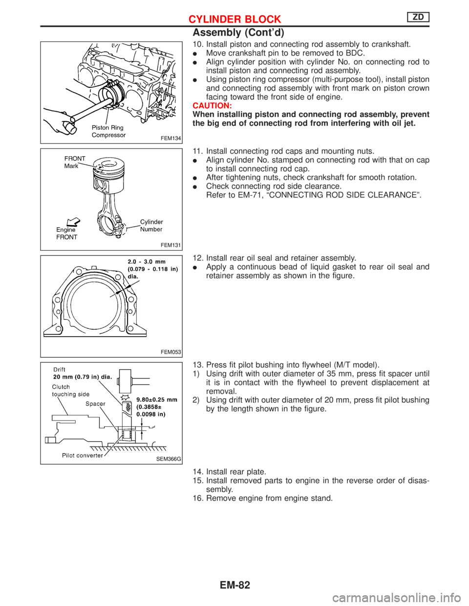
10. Install piston and connecting rod assembly to crankshaft.
IMove crankshaft pin to be removed to BDC.
IAlign cylinder position with cylinder No. on connecting rod to
install piston and connecting rod assembly.
IUsing piston ring compressor (multi-purpose tool), install piston
and connecting rod assembly with front mark on piston crown
facing toward the front side of engine.
CAUTION:
When installing piston and connecting rod assembly, prevent
the big end of connecting rod from interfering with oil jet.
11. Install connecting rod caps and mounting nuts.
IAlign cylinder No. stamped on connecting rod with that on cap
to install connecting rod cap.
IAfter tightening nuts, check crankshaft for smooth rotation.
ICheck connecting rod side clearance.
Refer to EM-71, ªCONNECTING ROD SIDE CLEARANCEº.
12. Install rear oil seal and retainer assembly.
IApply a continuous bead of liquid gasket to rear oil seal and
retainer assembly as shown in the figure.
13. Press fit pilot bushing into flywheel (M/T model).
1) Using drift with outer diameter of 35 mm, press fit spacer until
it is in contact with the flywheel to prevent displacement at
removal.
2) Using drift with outer diameter of 20 mm, press fit pilot bushing
by the length shown in the figure.
14. Install rear plate.
15. Install removed parts to engine in the reverse order of disas-
sembly.
16. Remove engine from engine stand.
FEM134
FEM131
FEM053
SEM366G
CYLINDER BLOCKZD
Assembly (Cont'd)
EM-82
Page 1203 of 1767

Parts Requiring Angular Tightening
ISome important engine parts are tightened using an angular-
tightening method rather than a torque setting method.
IIf these parts are tightened using a torque setting method, dis-
persal of the tightening force (axial bolt force) will be two or
three times that of the dispersal produced by using the correct
angular-tightening method.
IAlthough the torque setting values (described in this manual)
are equivalent to those used when bolts and nuts are tightened
with an angular-tightening method, they should be used for
reference only.
ITo assure the satisfactory maintenance of the engine, bolts and
nuts must be tightened using an angular-tightening method.
IBefore tightening the bolts and nuts, ensure that the thread and
seating surfaces are clean and then coated with engine oil.
IThe bolts and nuts which require the angular-tightening method
are as follows:
(1) Cylinder head bolts
(2) Connecting rod cap nuts
Liquid Gasket Application Procedure
a. Before applying liquid gasket, use a scraper to remove all
traces of old liquid gasket from mating surface and
grooves, and then completely clean any oil stains from
these portions.
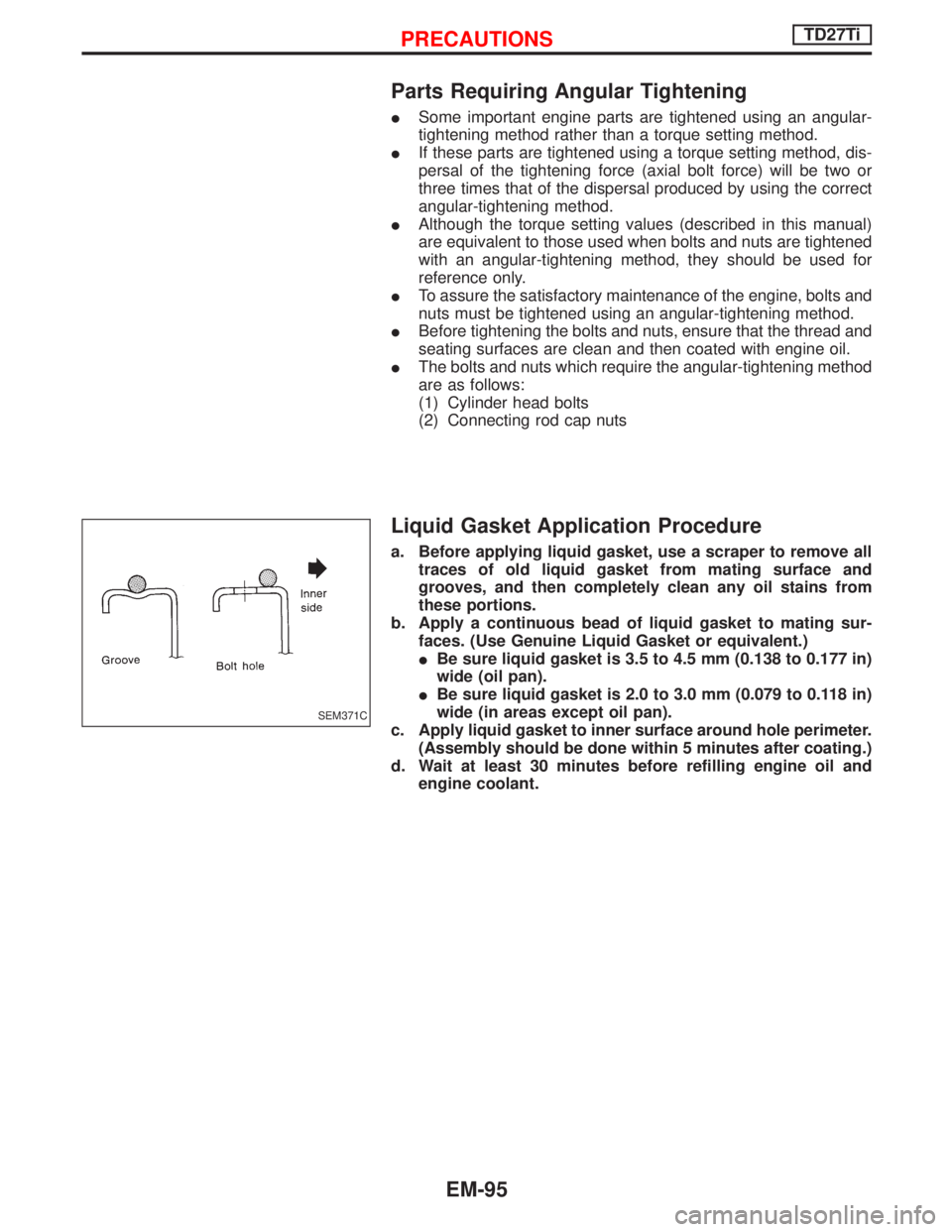
b. Apply a continuous bead of liquid gasket to mating sur-
faces. (Use Genuine Liquid Gasket or equivalent.)
IBe sure liquid gasket is 3.5 to 4.5 mm (0.138 to 0.177 in)
wide (oil pan).
IBe sure liquid gasket is 2.0 to 3.0 mm (0.079 to 0.118 in)
wide (in areas except oil pan).
c. Apply liquid gasket to inner surface around hole perimeter.
(Assembly should be done within 5 minutes after coating.)
d. Wait at least 30 minutes before refilling engine oil and
engine coolant.
SEM371C
PRECAUTIONSTD27Ti
EM-95
Page 1204 of 1767
Special Service Tools
*: Special tool or commercial equivalent
Tool number
Tool nameDescription
ST0501S000*
Engine stand assembly
q
1ST05011000
Engine stand
q
2ST05012000
Base
Disassembling and assembling
KV10106500*
Engine attachment
KV11103200*
Engine sub-attachment
q1KV10109210*
Valve spring
compressor
q
2KV10111200*
Adapter
Disassembling and assembling valve
components
KV10107900*
Valve oil seal puller
Disassembling valve oil seal
KV11103400
Valve oil seal drift
Installing valve oil seal
ST11033000*
Valve guide drift
Removing valve guide
PREPARATIONTD27Ti
EM-96
Page 1208 of 1767
q1Intake manifold
q
2Oil cooler
q
3Injection pump drive gearq
4Dust cover
q
5Engine revolution sensor
q
6Air conditioner compressorq
7Idler pulley
q
8Electronic injection pump
NEM324
ENGINE COMPONENTS Ð Outer PartsTD27Ti
EM-100
Page 1209 of 1767
q1Injection tube
q
2Spill tube
q
3Injection nozzleq
4Engine slinger
q
5Oil filter bracket
q
6Oil filterq
7Alternator adjusting bar & engine
slinger
q
8Turbocharger
q
9Exhaust manifold
NEM344
ENGINE COMPONENTS Ð Outer PartsTD27Ti
EM-101
Page 1210 of 1767
q1Cylinder block
q
2Oil pump
q
3Camshaft bushing
q
4Front plate
q
5Camshaft gear
q
6Snap ring
q
7Piston pin
q
8Connecting rod bearing
q
9Oil jet
q
10Crank pulleyq
11Main bearing
q
12Oil pan
q
13Thrust washer
q
14Crankshaft
q
15Pilot bushing
q
16Flywheel
q
17Connecting rod
q
18Piston
q
19Piston ringq
20Camshaft
q
21Rear oil seal retainer
q
22Rear oil seal
q
23Rear plate
q
24Vacuum pump
q
25Dipstick
q
26Drain plug
q
27Timing gear case
q
28Idler gear
YEM036
ENGINE COMPONENTS Ð Internal PartsTD27Ti
EM-102
Page 1211 of 1767

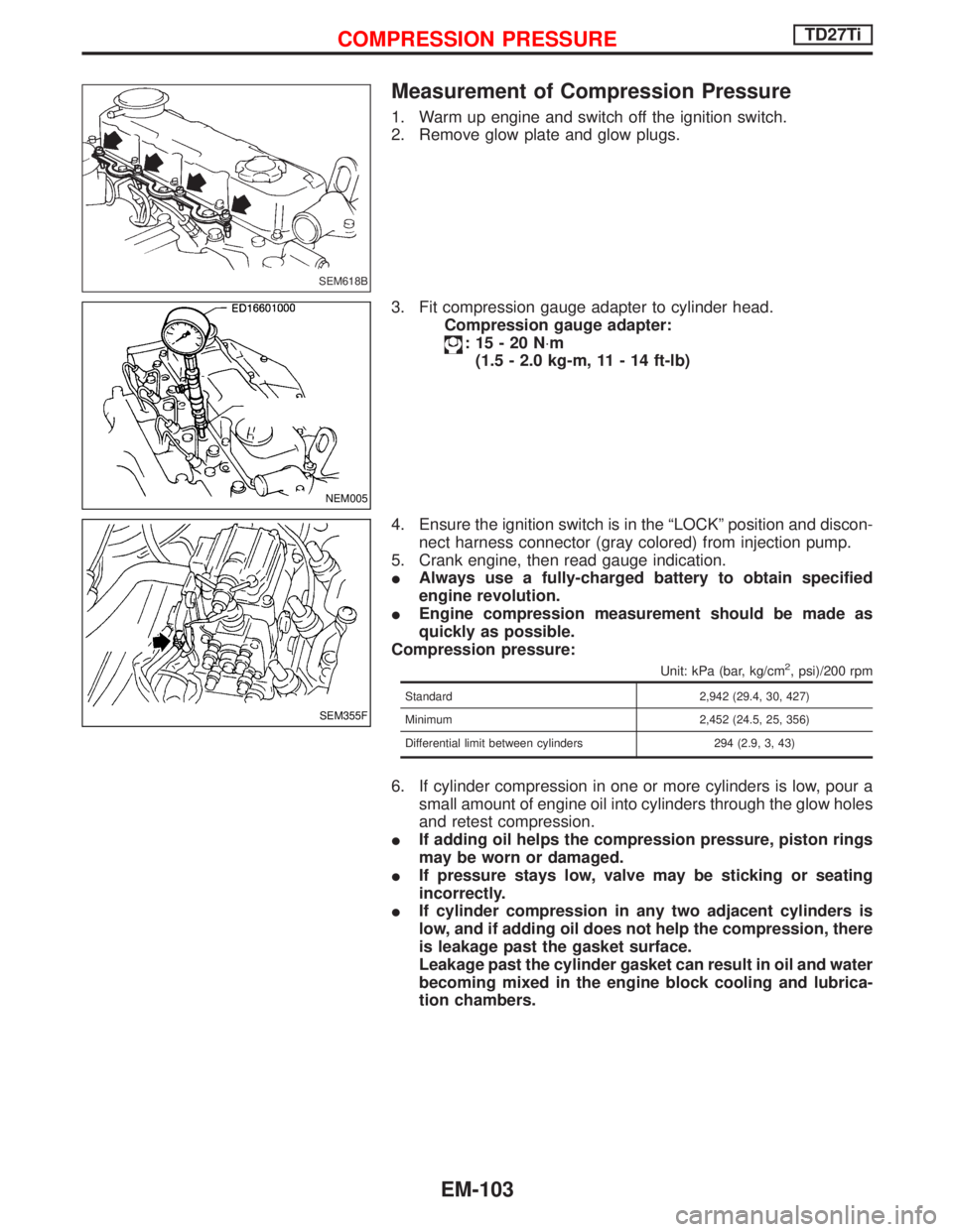
Measurement of Compression Pressure
1. Warm up engine and switch off the ignition switch.
2. Remove glow plate and glow plugs.
3. Fit compression gauge adapter to cylinder head.
Compression gauge adapter:
:15-20N×m
(1.5 - 2.0 kg-m, 11 - 14 ft-lb)
4. Ensure the ignition switch is in the ªLOCKº position and discon-
nect harness connector (gray colored) from injection pump.
5. Crank engine, then read gauge indication.
IAlways use a fully-charged battery to obtain specified
engine revolution.
IEngine compression measurement should be made as
quickly as possible.
Compression pressure:
Unit: kPa (bar, kg/cm2, psi)/200 rpm
Standard 2,942 (29.4, 30, 427)
Minimum 2,452 (24.5, 25, 356)
Differential limit between cylinders 294 (2.9, 3, 43)
6. If cylinder compression in one or more cylinders is low, pour a
small amount of engine oil into cylinders through the glow holes
and retest compression.
IIf adding oil helps the compression pressure, piston rings
may be worn or damaged.
IIf pressure stays low, valve may be sticking or seating
incorrectly.
IIf cylinder compression in any two adjacent cylinders is
low, and if adding oil does not help the compression, there
is leakage past the gasket surface.
Leakage past the cylinder gasket can result in oil and water
becoming mixed in the engine block cooling and lubrica-
tion chambers.
SEM618B
NEM005
SEM355F
COMPRESSION PRESSURETD27Ti
EM-103