Page 1130 of 1767
Removal and Installation
REMOVAL
1. Drain engine oil.
2. Remove the following parts.
IUnder guard
ICrossmember, differential member, front final drive assembly
IEngine gusset
3. Loosen and remove oil pan installation bolts in reverse order of
numbers in the figure.
4. Use a seal cutter (special service tool) to cut away liquid gas-
ket and remove oil pan.
5. Remove oil strainer.
YEM027
JEM773G
OIL PAN & OIL STRAINERZD
EM-22
Page 1136 of 1767
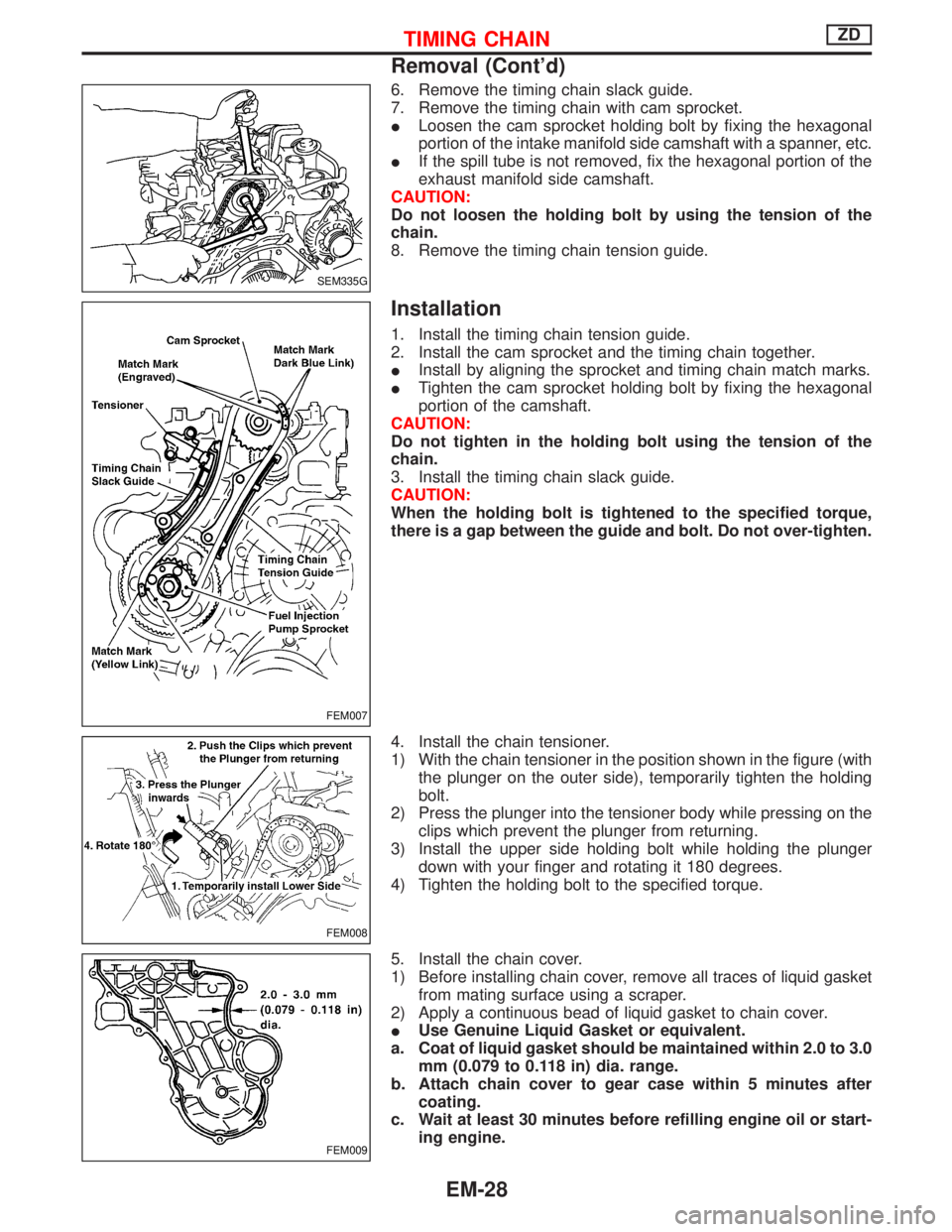
6. Remove the timing chain slack guide.
7. Remove the timing chain with cam sprocket.
ILoosen the cam sprocket holding bolt by fixing the hexagonal
portion of the intake manifold side camshaft with a spanner, etc.
IIf the spill tube is not removed, fix the hexagonal portion of the
exhaust manifold side camshaft.
CAUTION:
Do not loosen the holding bolt by using the tension of the
chain.
8. Remove the timing chain tension guide.
Installation
1. Install the timing chain tension guide.
2. Install the cam sprocket and the timing chain together.
IInstall by aligning the sprocket and timing chain match marks.
ITighten the cam sprocket holding bolt by fixing the hexagonal
portion of the camshaft.
CAUTION:
Do not tighten in the holding bolt using the tension of the
chain.
3. Install the timing chain slack guide.
CAUTION:
When the holding bolt is tightened to the specified torque,
there is a gap between the guide and bolt. Do not over-tighten.
4. Install the chain tensioner.
1) With the chain tensioner in the position shown in the figure (with
the plunger on the outer side), temporarily tighten the holding
bolt.
2) Press the plunger into the tensioner body while pressing on the
clips which prevent the plunger from returning.
3) Install the upper side holding bolt while holding the plunger
down with your finger and rotating it 180 degrees.
4) Tighten the holding bolt to the specified torque.
5. Install the chain cover.
1) Before installing chain cover, remove all traces of liquid gasket
from mating surface using a scraper.
2) Apply a continuous bead of liquid gasket to chain cover.
IUse Genuine Liquid Gasket or equivalent.
a. Coat of liquid gasket should be maintained within 2.0 to 3.0
mm (0.079 to 0.118 in) dia. range.
b. Attach chain cover to gear case within 5 minutes after
coating.
c. Wait at least 30 minutes before refilling engine oil or start-
ing engine.
SEM335G
FEM007
FEM008
FEM009
TIMING CHAINZD
Removal (Cont'd)
EM-28
Page 1139 of 1767
3. Remove injection tube and injection nozzle assembly. Refer to
EC section, ªInjection Tube and Injection Nozzleº in ªBASIC
SERVICE PROCEDUREº.
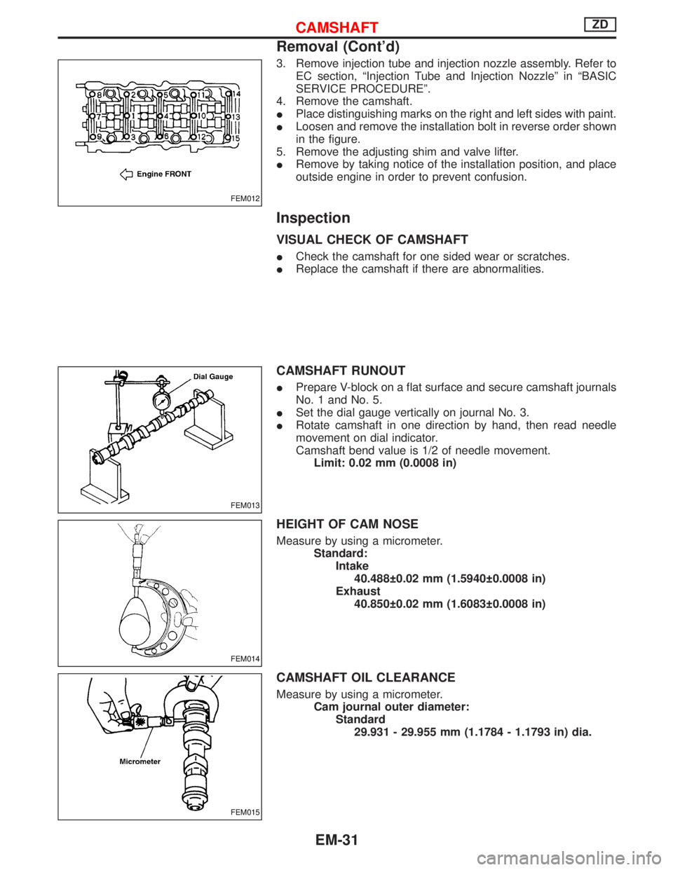
4. Remove the camshaft.
IPlace distinguishing marks on the right and left sides with paint.
ILoosen and remove the installation bolt in reverse order shown
in the figure.
5. Remove the adjusting shim and valve lifter.
IRemove by taking notice of the installation position, and place
outside engine in order to prevent confusion.
Inspection
VISUAL CHECK OF CAMSHAFT
ICheck the camshaft for one sided wear or scratches.
IReplace the camshaft if there are abnormalities.
CAMSHAFT RUNOUT
IPrepare V-block on a flat surface and secure camshaft journals
No. 1 and No. 5.
ISet the dial gauge vertically on journal No. 3.
IRotate camshaft in one direction by hand, then read needle
movement on dial indicator.
Camshaft bend value is 1/2 of needle movement.
Limit: 0.02 mm (0.0008 in)
HEIGHT OF CAM NOSE
Measure by using a micrometer.
Standard:
Intake
40.488 0.02 mm (1.5940 0.0008 in)
Exhaust
40.850 0.02 mm (1.6083 0.0008 in)
CAMSHAFT OIL CLEARANCE
Measure by using a micrometer.
Cam journal outer diameter:
Standard
29.931 - 29.955 mm (1.1784 - 1.1793 in) dia.
FEM012
FEM013
FEM014
FEM015
CAMSHAFTZD
Removal (Cont'd)
EM-31
Page 1144 of 1767
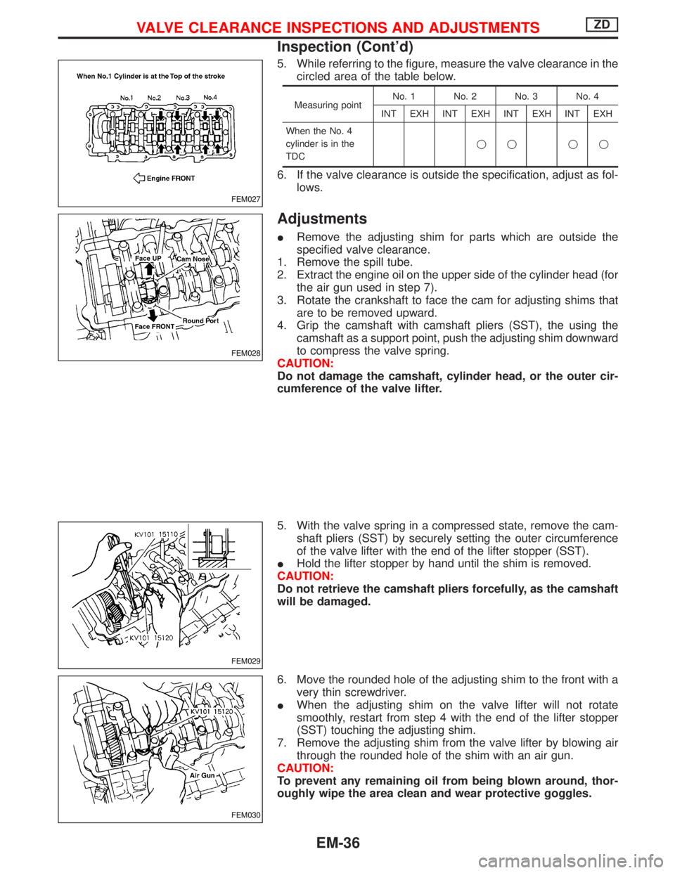
5. While referring to the figure, measure the valve clearance in the
circled area of the table below.
Measuring pointNo. 1 No. 2 No. 3 No. 4
INT EXH INT EXH INT EXH INT EXH
When the No. 4
cylinder is in the
TDCqq qq
6. If the valve clearance is outside the specification, adjust as fol-
lows.
Adjustments
IRemove the adjusting shim for parts which are outside the
specified valve clearance.
1. Remove the spill tube.
2. Extract the engine oil on the upper side of the cylinder head (for
the air gun used in step 7).
3. Rotate the crankshaft to face the cam for adjusting shims that
are to be removed upward.
4. Grip the camshaft with camshaft pliers (SST), the using the
camshaft as a support point, push the adjusting shim downward
to compress the valve spring.
CAUTION:
Do not damage the camshaft, cylinder head, or the outer cir-
cumference of the valve lifter.
5. With the valve spring in a compressed state, remove the cam-
shaft pliers (SST) by securely setting the outer circumference
of the valve lifter with the end of the lifter stopper (SST).
IHold the lifter stopper by hand until the shim is removed.
CAUTION:
Do not retrieve the camshaft pliers forcefully, as the camshaft
will be damaged.
6. Move the rounded hole of the adjusting shim to the front with a
very thin screwdriver.
IWhen the adjusting shim on the valve lifter will not rotate
smoothly, restart from step 4 with the end of the lifter stopper
(SST) touching the adjusting shim.
7. Remove the adjusting shim from the valve lifter by blowing air
through the rounded hole of the shim with an air gun.
CAUTION:
To prevent any remaining oil from being blown around, thor-
oughly wipe the area clean and wear protective goggles.
FEM027
FEM028
FEM029
FEM030
VALVE CLEARANCE INSPECTIONS AND ADJUSTMENTSZD
Inspection (Cont'd)
EM-36
Page 1147 of 1767
Removal
1. Remove the engine assembly.
Refer to ªENGINE REMOVALº, EM-63.
2. Place the engine on an engine stand (SST).
Refer to ªCYLINDER BLOCKº, EM-67.
3. Remove the following.
IAuto tensioner bracket
IAir conditioner bracket
IAlternator bracket
IOil tube
IVacuum pump
IRocker cover
IOil pan (upper, lower)
IInjection tube
ISpill tube
IHigh pressure nozzle assembly
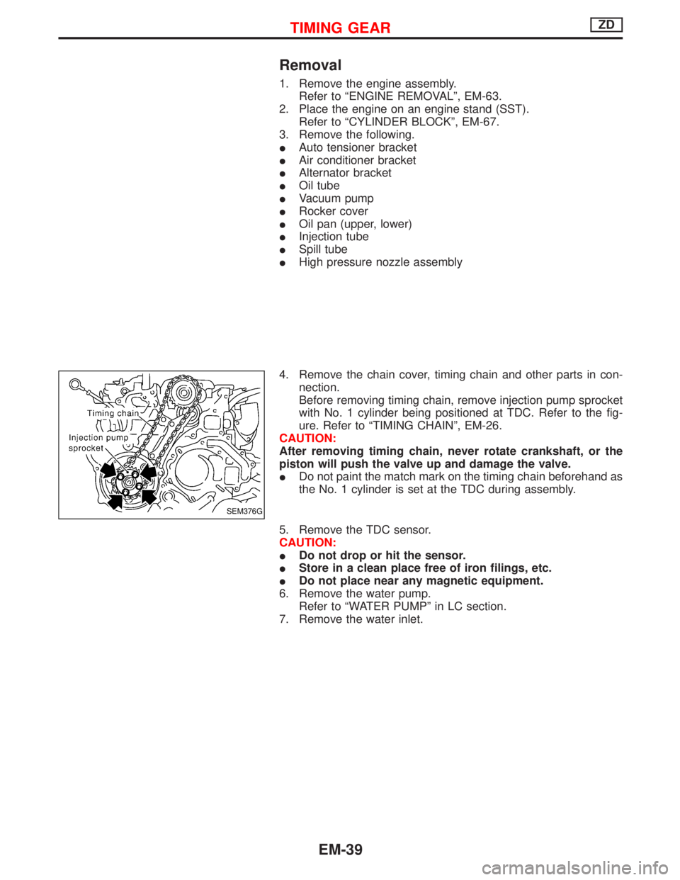
4. Remove the chain cover, timing chain and other parts in con-
nection.
Before removing timing chain, remove injection pump sprocket
with No. 1 cylinder being positioned at TDC. Refer to the fig-
ure. Refer to ªTIMING CHAINº, EM-26.
CAUTION:
After removing timing chain, never rotate crankshaft, or the
piston will push the valve up and damage the valve.
IDo not paint the match mark on the timing chain beforehand as
the No. 1 cylinder is set at the TDC during assembly.
5. Remove the TDC sensor.
CAUTION:
IDo not drop or hit the sensor.
IStore in a clean place free of iron filings, etc.
IDo not place near any magnetic equipment.
6. Remove the water pump.
Refer to ªWATER PUMPº in LC section.
7. Remove the water inlet.
SEM376G
TIMING GEARZD
EM-39
Page 1148 of 1767
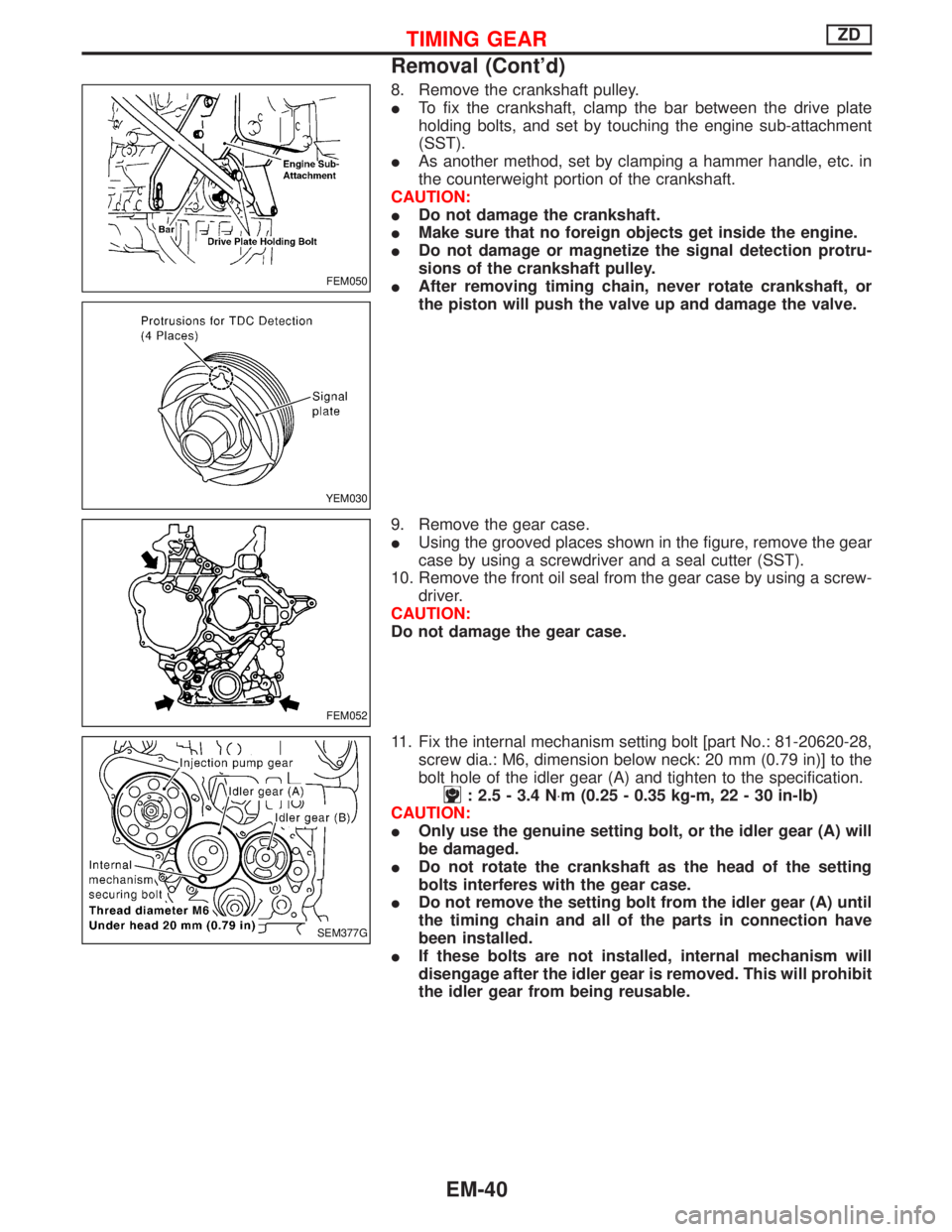
8. Remove the crankshaft pulley.
ITo fix the crankshaft, clamp the bar between the drive plate
holding bolts, and set by touching the engine sub-attachment
(SST).
IAs another method, set by clamping a hammer handle, etc. in
the counterweight portion of the crankshaft.
CAUTION:
IDo not damage the crankshaft.
IMake sure that no foreign objects get inside the engine.
IDo not damage or magnetize the signal detection protru-
sions of the crankshaft pulley.
IAfter removing timing chain, never rotate crankshaft, or
the piston will push the valve up and damage the valve.
9. Remove the gear case.
IUsing the grooved places shown in the figure, remove the gear
case by using a screwdriver and a seal cutter (SST).
10. Remove the front oil seal from the gear case by using a screw-
driver.
CAUTION:
Do not damage the gear case.
11. Fix the internal mechanism setting bolt [part No.: 81-20620-28,
screw dia.: M6, dimension below neck: 20 mm (0.79 in)] to the
bolt hole of the idler gear (A) and tighten to the specification.
: 2.5 - 3.4 N×m (0.25 - 0.35 kg-m, 22 - 30 in-lb)
CAUTION:
IOnly use the genuine setting bolt, or the idler gear (A) will
be damaged.
IDo not rotate the crankshaft as the head of the setting
bolts interferes with the gear case.
IDo not remove the setting bolt from the idler gear (A) until
the timing chain and all of the parts in connection have
been installed.
IIf these bolts are not installed, internal mechanism will
disengage after the idler gear is removed. This will prohibit
the idler gear from being reusable.
FEM050
YEM030
FEM052
SEM377G
TIMING GEARZD
Removal (Cont'd)
EM-40
Page 1155 of 1767
![NISSAN TERRANO 2002 Service Repair Manual 4. Install the front oil seal to the gear case.
IApply engine oil to the fitting side.
IEvenly insert the front oil seal using a drift [outer dia.: approx.
64 mm (2.52 in)] completely.
CAUTION:
Make s NISSAN TERRANO 2002 Service Repair Manual 4. Install the front oil seal to the gear case.
IApply engine oil to the fitting side.
IEvenly insert the front oil seal using a drift [outer dia.: approx.
64 mm (2.52 in)] completely.
CAUTION:
Make s](/manual-img/5/57393/w960_57393-1154.png)
4. Install the front oil seal to the gear case.
IApply engine oil to the fitting side.
IEvenly insert the front oil seal using a drift [outer dia.: approx.
64 mm (2.52 in)] completely.
CAUTION:
Make sure the oil seal does not spill off the end side of the gear
case.
5. Install the gear case.
1) Before installing gear case, remove all traces of liquid gasket
from mating surface using a scraper.
2) Align gasket with dowel and install.
3) Install the O-rings to the gear case.
IThe O-ring at the top position shown in the figure can be
installed in during cylinder head installation.
4) Apply a continuous bead of liquid gasket to gear case.
IUse Genuine Liquid Gasket or equivalent.
a. Coat of liquid gasket should be maintained within 2.0 to 3.0
mm (0.079 to 0.118 in) dia. range.
b. Attach gear case to cylinder block within 5 minutes after
coating.
c. Wait at least 30 minutes before refilling engine oil or start-
ing engine.
FEM043
FEM044
SEM353G
FEM045
TIMING GEARZD
Installation (Cont'd)
EM-47
Page 1159 of 1767
CRANKSHAFT FRONT OIL SEAL
1. Remove the front cover. Refer to ªTIMING GEARº.
2. Remove front oil seal with a suitable tool.
3. Apply engine oil to new oil seal and install oil seal using a suit-
able tool.
CRANKSHAFT REAR OIL SEAL
1. Remove oil pan assembly. Refer to EM-22, ªOIL PANº.
2. Remove clutch cover assembly.
3. Remove flywheel and rear plate.
4. Remove oil seal retainer assembly.
5. Apply a continuous bead of liquid gasket to rear oil seal
retainer.
a. Coat of liquid gasket should be maintained within 2.0 to 3.0
mm (0.079 to 0.118 in) dia. range.
b. Attach oil seal retainer to cylinder block within five min-
utes after coating.
c. Wait at least 30 minutes before refilling engine oil or start-
ing engine.
d. Use Genuine Liquid Gasket or equivalent.
SEM358G
FEM044
SLC822
FEM053
OIL SEAL REPLACEMENTZD
EM-51