Page 1607 of 1767
Precautions
IWhen installing each rubber part, final tightening must be car-
ried out under unladen condition* with tires on ground.
* Fuel, radiator coolant and engine oil full. Spare tire, jack,
hand tools and mats in designated positions.
IUse Tool when removing or installing brake tubes.
IIf suspension or suspension parts are dismounted, check wheel
alignment and adjust if necessary.
IDo not jack up vehicle at lower link.
Preparation
SPECIAL SERVICE TOOLS
*: Special tool or commercial equivalent
Tool number
Tool nameDescription
GG94310000*
Flare nut torque wrench
Removing or installing brake piping
KV40101000*
Axle stand
Removing rear axle shaft
ST36230000*
Sliding hammer
Removing rear axle shaft
ST38020000
Bearing lock nut wrench
Removing wheel bearing lock nut
KV401-06700-B
Rear axle shaft bearing
puller
Remove wheel bearing and ABS rotor
NI-110
Rear axle shaft guide
Installing rear axle shaft
SBR820B
PRECAUTIONS AND PREPARATION
RA-2
Page 1716 of 1767

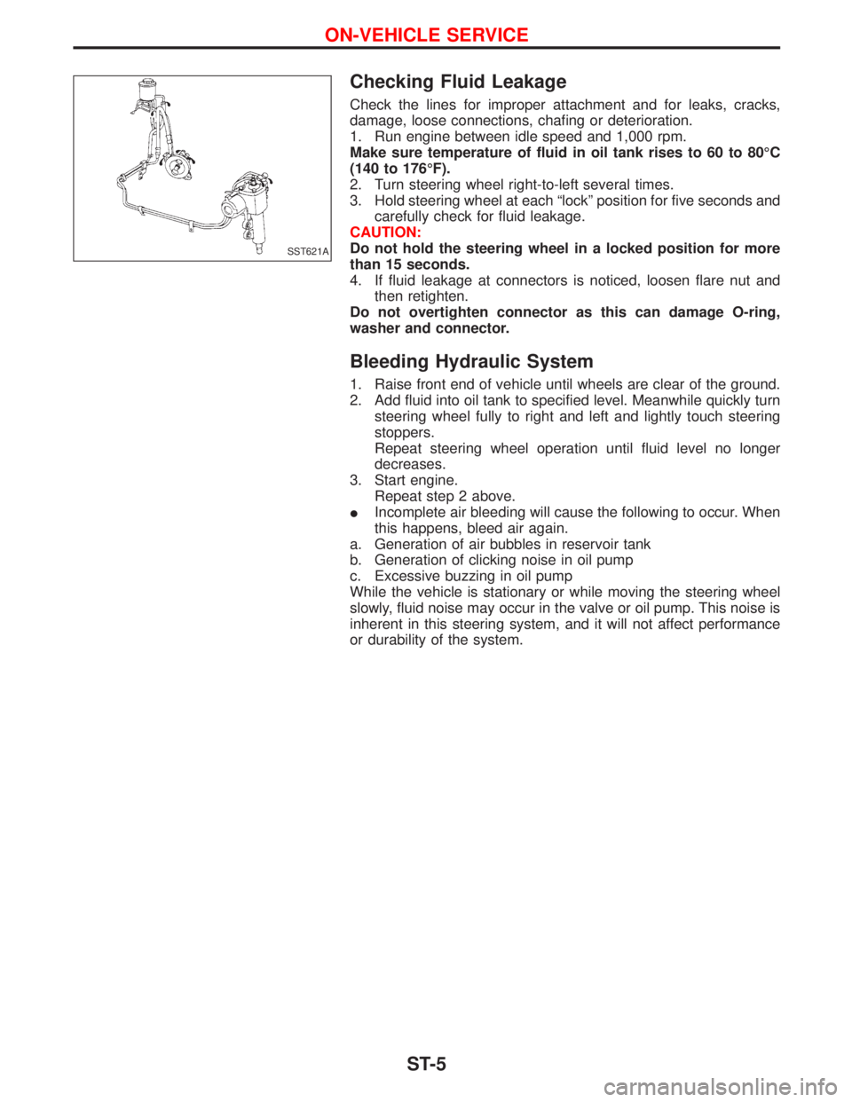
Checking Fluid Leakage
Check the lines for improper attachment and for leaks, cracks,
damage, loose connections, chafing or deterioration.
1. Run engine between idle speed and 1,000 rpm.
Make sure temperature of fluid in oil tank rises to 60 to 80ÉC
(140 to 176ÉF).
2. Turn steering wheel right-to-left several times.
3. Hold steering wheel at each ªlockº position for five seconds and
carefully check for fluid leakage.
CAUTION:
Do not hold the steering wheel in a locked position for more
than 15 seconds.
4. If fluid leakage at connectors is noticed, loosen flare nut and
then retighten.
Do not overtighten connector as this can damage O-ring,
washer and connector.
Bleeding Hydraulic System
1. Raise front end of vehicle until wheels are clear of the ground.
2. Add fluid into oil tank to specified level. Meanwhile quickly turn
steering wheel fully to right and left and lightly touch steering
stoppers.
Repeat steering wheel operation until fluid level no longer
decreases.
3. Start engine.
Repeat step 2 above.
IIncomplete air bleeding will cause the following to occur. When
this happens, bleed air again.
a. Generation of air bubbles in reservoir tank
b. Generation of clicking noise in oil pump
c. Excessive buzzing in oil pump
While the vehicle is stationary or while moving the steering wheel
slowly, fluid noise may occur in the valve or oil pump. This noise is
inherent in this steering system, and it will not affect performance
or durability of the system.
SST621A
ON-VEHICLE SERVICE
ST-5
Page 1717 of 1767

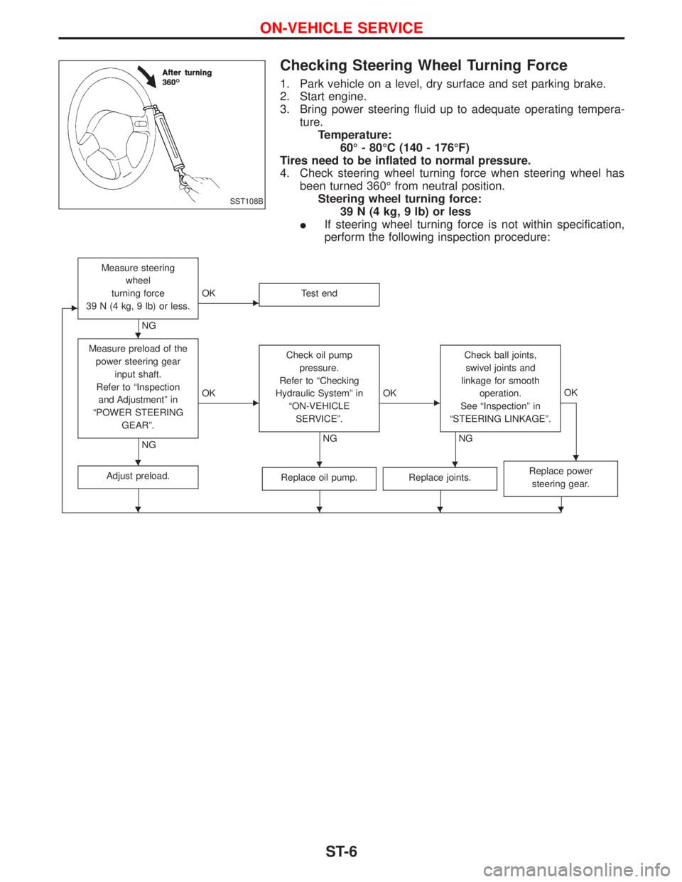
Checking Steering Wheel Turning Force
1. Park vehicle on a level, dry surface and set parking brake.
2. Start engine.
3. Bring power steering fluid up to adequate operating tempera-
ture.
Temperature:
60É - 80ÉC (140 - 176ÉF)
Tires need to be inflated to normal pressure.
4. Check steering wheel turning force when steering wheel has
been turned 360É from neutral position.
Steering wheel turning force:
39 N (4 kg, 9 lb) or less
IIf steering wheel turning force is not within specification,
perform the following inspection procedure:
E
Measure steering
wheel
turning force
39 N (4 kg, 9 lb) or less.
NG
EOK Test end
Measure preload of the
power steering gear
input shaft.
Refer to ªInspection
and Adjustmentº in
ªPOWER STEERING
GEARº.
NG
EOKCheck oil pump
pressure.
Refer to ªChecking
Hydraulic Systemº in
ªON-VEHICLE
SERVICEº.
NG
EOKCheck ball joints,
swivel joints and
linkage for smooth
operation.
See ªInspectionº in
ªSTEERING LINKAGEº.
NGOK
Adjust preload.Replace oil pump.Replace joints.Replace power
steering gear.
SST108B
H
HHHH
HHHH
ON-VEHICLE SERVICE
ST-6
Page 1718 of 1767

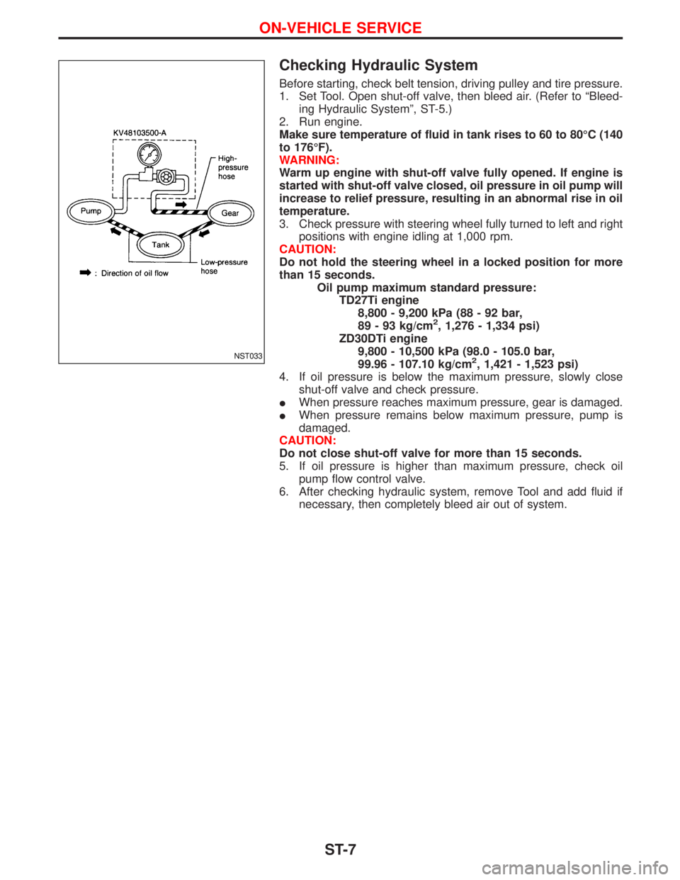
Checking Hydraulic System
Before starting, check belt tension, driving pulley and tire pressure.
1. Set Tool. Open shut-off valve, then bleed air. (Refer to ªBleed-
ing Hydraulic Systemº, ST-5.)
2. Run engine.
Make sure temperature of fluid in tank rises to 60 to 80ÉC (140
to 176ÉF).
WARNING:
Warm up engine with shut-off valve fully opened. If engine is
started with shut-off valve closed, oil pressure in oil pump will
increase to relief pressure, resulting in an abnormal rise in oil
temperature.
3. Check pressure with steering wheel fully turned to left and right
positions with engine idling at 1,000 rpm.
CAUTION:
Do not hold the steering wheel in a locked position for more
than 15 seconds.
Oil pump maximum standard pressure:
TD27Ti engine
8,800 - 9,200 kPa (88 - 92 bar,
89 - 93 kg/cm
2, 1,276 - 1,334 psi)
ZD30DTi engine
9,800 - 10,500 kPa (98.0 - 105.0 bar,
99.96 - 107.10 kg/cm
2, 1,421 - 1,523 psi)
4. If oil pressure is below the maximum pressure, slowly close
shut-off valve and check pressure.
IWhen pressure reaches maximum pressure, gear is damaged.
IWhen pressure remains below maximum pressure, pump is
damaged.
CAUTION:
Do not close shut-off valve for more than 15 seconds.
5. If oil pressure is higher than maximum pressure, check oil
pump flow control valve.
6. After checking hydraulic system, remove Tool and add fluid if
necessary, then completely bleed air out of system.NST033
ON-VEHICLE SERVICE
ST-7
Page 1733 of 1767
General Specifications
Models All
Steering gear type ZF 8054
Turns of steering
wheel
(Lock to lock)3.86
Overall gear ratio 17.1 : 1
Steering column type Collapsible, adjustable height
Inspection and Adjustment
STEERING WHEEL AND COLUMN
Applied model AIR BAG
Steering wheel axial play mm (in) 0 (0)
Steering wheel play mm (in) 35 (1.38) or less
Steering column length ªLº mm (in)830.5 - 832.7
(32.697 - 32.783)
EST018
STEERING GEAR AND LINKAGE
Ball joint and swivel joint
Rotating torque ªBº N×m (kg-m, in-lb)0.5 - 5.0
(0.05 - 0.51,
4 - 44)
Axial end play ªCº mm (in) 0 - 0.2 (0 - 0.008)
Radial play ªDº mm (in) 0 (0)
Length ªLº mm (in) 287 (11.30)
SST583B
OIL PUMP
Unit: kPa (bar, kg/cm2, psi)
Engine ZD30DDTi TD27Ti
Make UNISIA
Max. pressure9,800 - 10,500
(98.0 - 105.0,
99.96 - 107.10,
1,421 - 1,523)8,800 - 9,200
(88 - 92,
89 - 93,
1,276 - 1,334)
SERVICE DATA AND SPECIFICATIONS (SDS)
ST-22