Page 1433 of 1767
OIL FILTER
The oil filter is an element type. Refer to ªChanging Oil Filterº in MA
section.
Oil Cooler
REMOVAL AND INSTALLATION
1. Drain engine oil and coolant.
Remove catalyst and turbocharger. Refer to ªCATALYST AND
TURBOCHARGERº in EM section.
2. Remove bolts A to C then remove oil cooler assembly.
IDo not remove ªDº nuts when removing oil cooler assem-
bly.
Bolt length:
A: 20 mm (0.79 in)
B: 45 mm (1.77 in)
C: 65 mm (2.56 in)
3. Installation is in reverse order of removal.
IDo not spill coolant on the drive belt.
INSPECTION
1. Check oil cooler for cracks.
2. Check oil cooler for clogging by blowing through coolant inlet.
If necessary, replace oil cooler assembly.
YLC030
JLC381B
ENGINE LUBRICATION SYSTEMZD
Oil Jet (Cont'd)
LC-8
Page 1440 of 1767

REMOVAL AND INSTALLATION
1. Remove under cover.
2. Drain engine coolant. Refer to MA section, ªChanging Engine
Coolantº.
3. Remove air cleaner case, air duct and resonator.
4. Remove battery (right side).
5. Remove radiator shroud (lower).
6. Remove radiator shroud (front).
7. Disconnect radiator hose (upper and lower).
8. Disconnect reservoir tank hose.
9. Disconnect A/T oil cooler hose (Only A/T models).
10. Remove radiator.
11. After repairing or replacing radiator, install all removed parts in
reverse order of removal.
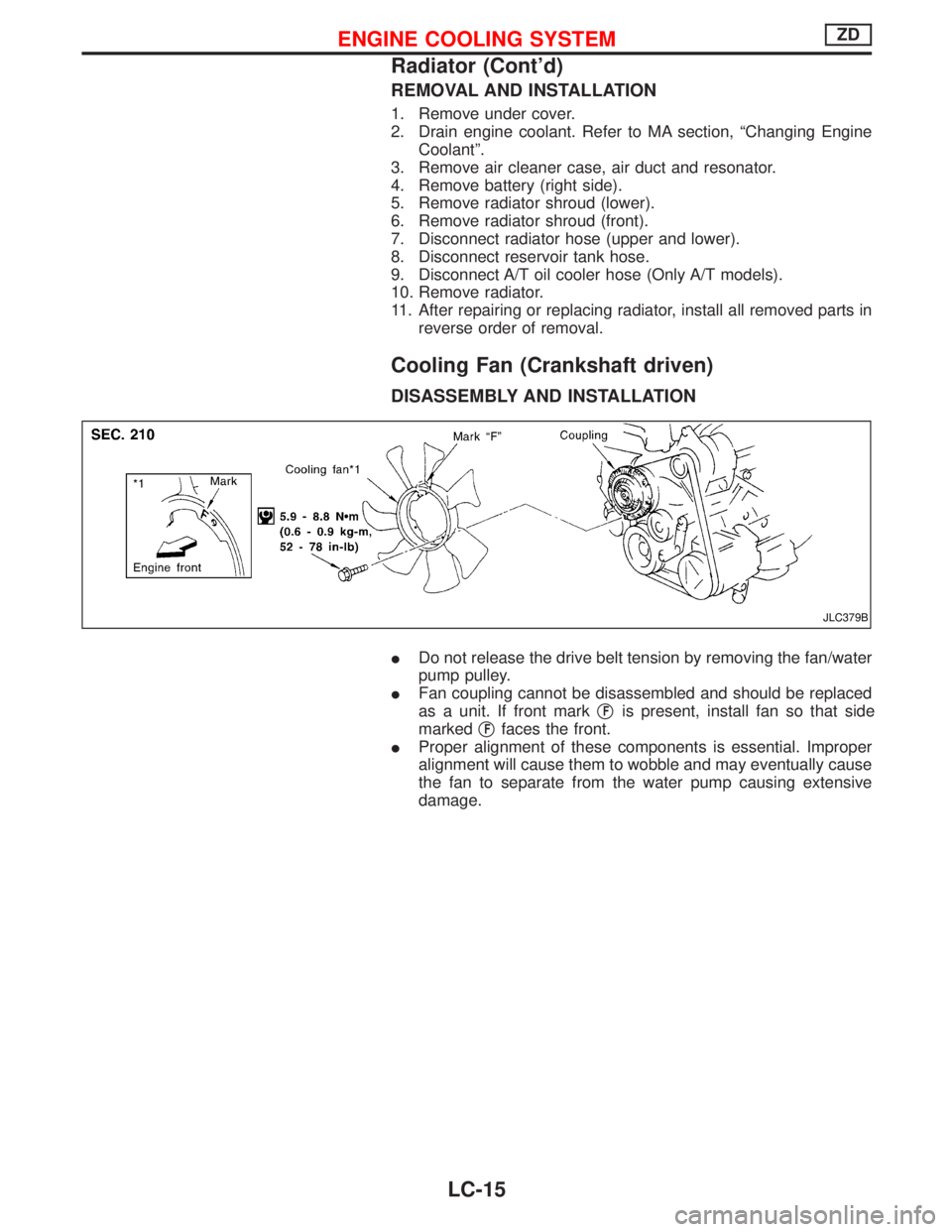
Cooling Fan (Crankshaft driven)
DISASSEMBLY AND INSTALLATION
IDo not release the drive belt tension by removing the fan/water
pump pulley.
IFan coupling cannot be disassembled and should be replaced
as a unit. If front markq
Fis present, install fan so that side
markedq
Ffaces the front.
IProper alignment of these components is essential. Improper
alignment will cause them to wobble and may eventually cause
the fan to separate from the water pump causing extensive
damage.
JLC379B
ENGINE COOLING SYSTEMZD
Radiator (Cont'd)
LC-15
Page 1442 of 1767

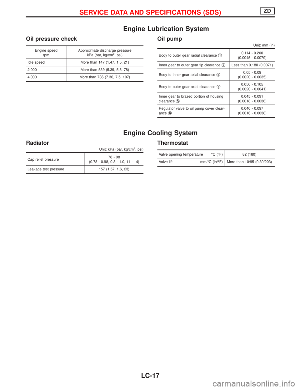
Engine Lubrication System
Oil pressure check
Engine speed
rpmApproximate discharge pressure
kPa (bar, kg/cm2, psi)
Idle speed More than 147 (1.47, 1.5, 21)
2,000 More than 539 (5.39, 5.5, 78)
4,000 More than 736 (7.36, 7.5, 107)
Oil pump
Unit: mm (in)
Body to outer gear radial clearanceq10.114 - 0.200
(0.0045 - 0.0079)
Inner gear to outer gear tip clearanceq
2Less than 0.180 (0.0071)
Body to inner gear axial clearanceq
30.05 - 0.09
(0.0020 - 0.0035)
Body to outer gear axial clearanceq
40.050 - 0.105
(0.0020 - 0.0041)
Inner gear to brazed portion of housing
clearanceq
50.045 - 0.091
(0.0018 - 0.0036)
Regulator valve to oil pump cover clear-
anceq
60.040 - 0.097
(0.0016 - 0.0038)
Engine Cooling System
Radiator
Unit: kPa (bar, kg/cm2, psi)
Cap relief pressure78-98
(0.78 - 0.98, 0.8 - 1.0, 11 - 14)
Leakage test pressure 157 (1.57, 1.6, 23)
Thermostat
Valve opening temperature ÉC (ÉF) 82 (180)
Valve lift mm/ÉC (in/ÉF) More than 10/95 (0.39/203)
SERVICE DATA AND SPECIFICATIONS (SDS)ZD
LC-17
Page 1444 of 1767
LIQUID GASKET APPLICATION PROCEDURE
a. Before applying liquid gasket, use a scraper to remove all
traces of old liquid gasket from mating surface.
b. Apply a continuous bead of liquid gasket to mating sur-
faces.
(Use Genuine Liquid Gasket or equivalent.)
IBe sure liquid gasket is 3.5 to 4.5 mm (0.138 to 0.177
in) wide (for oil pan).
IBe sure liquid gasket is 2.0 to 3.0 mm (0.079 to 0.118
in) wide (in areas except oil pan).
c. Apply liquid gasket to inner sealing surface around hole
perimeter area.
(Assembly should be done within 5 minutes after coating.)
d. Wait at least 30 minutes before refilling engine oil and
engine coolant.
SEM371C
PRECAUTIONTD27Ti
LC-19
Page 1446 of 1767
Oil Pressure Check
WARNING:
IBe careful not to burn yourself, as the engine and oil may
be hot.
IOil pressure check should be done in ªNeutralº gear posi-
tion.
1. Check oil level.
2. Remove oil pressure switch.
3. Install pressure gauge.
4. Start engine and warm it up to normal operating temperature.
5. Check oil pressure with engine running under no-load.
Engine rpmApproximate discharge pressure
kPa (bar, kg/cm2, psi)
Idle speed More than 78 (0.78, 0.8, 11)
3,000 294 - 392 (2.94 - 3.92, 3.0 - 4.0, 43 - 57)
If difference is extreme, check oil passage and oil pump for oil
leaks.
6. Install oil pressure switch.
Use proper liquid sealant.
Oil pressure switch:
:10-13N×m (1.0 - 1.3 kg-m, 87 - 113 in-lb)
SLC964
SLC003A
ENGINE LUBRICATION SYSTEMTD27Ti
LC-21
Page 1447 of 1767
Oil Pump
OIL PUMP INSPECTION
1. Inspect pump body, gears and drive shaft for wear and dam-
age.
2. Using a feeler gauge and fuse wire, check the following clear-
ances.
Gear side clearance:
Less than 0.13 mm (0.0051 in)
Gear backlash:
Less than 0.43 mm (0.0169 in)
3. Measure inside diameter ªAº of bushing.
A: 13.012 - 13.098 mm (0.5123 - 0.5157 in)
MLC128A
SLC966
SLC967
SLC968
ENGINE LUBRICATION SYSTEMTD27Ti
LC-22
Page 1448 of 1767
4. Measure outside diameter ªBº of drive gear shaft.
B: 12.974 - 12.992 mm (0.5108 - 0.5115 in)
5. Calculate oil pump bushing clearance.
Oil pump bushing clearance (A þ B):
Less than 0.15 mm (0.0059 in)
If it exceeds the limit replace oil pump bushing or entire oil
pump assembly.
SLC969
NLC057
ENGINE LUBRICATION SYSTEMTD27Ti
Oil Pump (Cont'd)
LC-23
Page 1449 of 1767
Oil Filter Bracket
q1O-ring
q
2Oil pump relief valveq
3Oil filter
q
4Oil filter bracketq
5Oil filter relief valve
q
6Protection shield
OIL PUMP RELIEF VALVE INSPECTION
1. Visually inspect components for wear and damage.
2. Coat relief valve with engine oil and check that it falls smoothly
into the valve hole by its own weight.
If damaged, replace oil pump relief valve set.
OIL FILTER RELIEF VALVE INSPECTION
Inspect oil filter short valve for movement, cracks and breaks by
pushing the ball.
If damaged, replace oil filter bracket assembly.
NLC056
ENGINE LUBRICATION SYSTEMTD27Ti
LC-24