Page 12 of 132
2-1
2
EAU00026
2-DESCRIPTION Left view1. Shift pedal (page 3-10)
2. Starter (choke) knob (page 3-14)
3. Fuel tank cap (page 3-11)
4. Fuel cock (page 3-13)
5. Battery (page 7-32)
6. Fuse box 2 (page 7-34)7. Side case (page 3-17)
8. Helmet holder (page 3-15)
9. License light (page 7-37)
10. Tail/brake light (page 7-36)
11. Rear turn signal lights (page 7-36)
E_5jc.book Page 1 Monday, January 22, 2001 12:12 PM
Page 13 of 132
DESCRIPTION
2-2
2
Right view12. Muffler
13. Owner’s tool kit (page 7-1)
14. Helmet holder (page 3-15)
15. Travel trunk (page 3-17)
16. Passenger seat
17. Shock absorber assembly air valve (page 3-20)
18. Rider seat (page 3-15)
19. Fuel tank (page 3-12)
20. Front fork air valve (page 3-19)21. Headlight (page 7-35)
22. Front turn signal lights (page 7-36)
23. Fuse box 1 (page 7-33)
24. Brake pedal (page 3-11)
25. Engine oil level check window (page 7-12)
26. Rider footrest
27. Coolant reservoir (page 7-15)
28. Passenger footrest
E_5jc.book Page 2 Monday, January 22, 2001 12:12 PM
Page 18 of 132

INSTRUMENT AND CONTROL FUNCTIONS
3-3
3
EAU03034
Indicator and warning lights
EAU03299
1. Turn signal indicator lights
“” / “ ”
The corresponding indicator light flash-
es when the turn signal switch is
pushed to the left or right.
EAU00063
2. High beam indicator light “ ”
This indicator light comes on when the
high beam of the headlight is switched
on.
EAU03201
3. Oil level warning light “ ”
This warning light comes on when the
engine oil level is low.
The electrical circuit of the warning light
can be checked according to the fol-
lowing procedure.
1. Set the engine stop switch to “ ”
and turn the key to “ON”.
2. Shift the transmission into the neu-
tral position or pull the clutch lever.
3. Push the start switch. If the warn-
ing light does not come on while
pushing the start switch, have a
Yamaha dealer check the electri-
cal circuit.
NOTE:@ Even if the oil level is sufficient, the
warning light may flicker when riding on
a slope or during sudden acceleration
or deceleration, but this is not a mal-
function. @
EAU01774
4. Overdrive indicator light “O/D”
This indicator light comes on when the
transmission is in overdrive (5th gear).
EAU00091
5. Engine trouble warning light
“”
This warning light comes on or flashes
when an electrical circuit monitoring
the engine is defective. When this oc-
curs, have the Yamaha dealer check
the self-diagnosis system.
E_5jc.book Page 3 Monday, January 22, 2001 12:12 PM
Page 24 of 132

INSTRUMENT AND CONTROL FUNCTIONS
3-9
3
EAU00118
Handlebar switches
EAU00119
1. Pass switch “ ”
Press this switch to flash the headlight.
EAU03888
2. Dimmer switch “ / ”
Set this switch to “ ” for the high
beam and to “ ” for the low beam.
EAU03889
3. Turn signal switch “ / ”
To signal a right-hand turn, push this
switch to “ ”. To signal a left-hand
turn, push this switch to “ ”. When
released, the switch returns to the cen-
ter position. To cancel the turn signal
lights, push the switch in after it has re-
turned to the center position.
EAU00129
4. Horn switch “ ”
Press this switch to sound the horn.
EAU03890
5. Engine stop switch “ / ”
Set this switch to “ ” before starting
the engine. Set this switch to “ ” to
stop the engine in case of an emergen-
cy, such as when the motorcycle over-
turns or when the throttle cable is
stuck.
EAU03966
6. Light switch “ / / ”
Set this switch to “ ” to turn on the
auxiliary light, meter lighting, taillight
and license plate light. Set the switch to
“ ” to turn on the headlight also. Set
the switch to “ ” to turn off all the
lights.
E_5jc.book Page 9 Monday, January 22, 2001 12:12 PM
Page 73 of 132

7
PERIODIC MAINTENANCE AND MINOR REPAIR
Owner’s tool kit .................................................... 7-1
Periodic maintenance and lubrication chart ......... 7-3
Removing and installing cowlings and panels ..... 7-6
Checking the spark plugs .................................. 7-11
Engine oil and oil filter cartridge ........................ 7-12
Final gear oil ...................................................... 7-15
Checking the coolant level ................................. 7-15
Cleaning the air filter elements .......................... 7-17
Adjusting the carburetors ................................... 7-19
Adjusting the engine idling speed ...................... 7-20
Adjusting the throttle cable free play .................. 7-21
Adjusting the valve clearance ............................ 7-21
Tires ................................................................... 7-21
Cast wheels ....................................................... 7-24
Clutch lever free play ......................................... 7-25
Adjusting the brake lever free play ..................... 7-25
Adjusting the brake pedal position ..................... 7-26
Adjusting the rear brake light switch .................. 7-26Checking the front and rear brake pads ............ 7-27
Checking the brake and clutch fluid levels ........ 7-28
Changing the brake and clutch fluids ................ 7-29
Checking and lubricating the brake and
shift pedals ...................................................... 7-29
Checking and lubricating the brake and
clutch levers .................................................... 7-30
Checking and lubricating the sidestand ............ 7-30
Checking the front fork ...................................... 7-31
Checking the steering ....................................... 7-31
Battery ............................................................... 7-32
Replacing the fuses .......................................... 7-33
Replacing the headlight bulb ............................. 7-35
Replacing a turn signal light bulb or the
tail/brake light bulb .......................................... 7-36
Replacing the license plate light bulb ................ 7-37
Troubleshooting ................................................. 7-37
Troubleshooting charts ...................................... 7-38
E_5jc.book Page 1 Monday, January 22, 2001 12:12 PM
Page 107 of 132

PERIODIC MAINTENANCE AND MINOR REPAIR
7-34
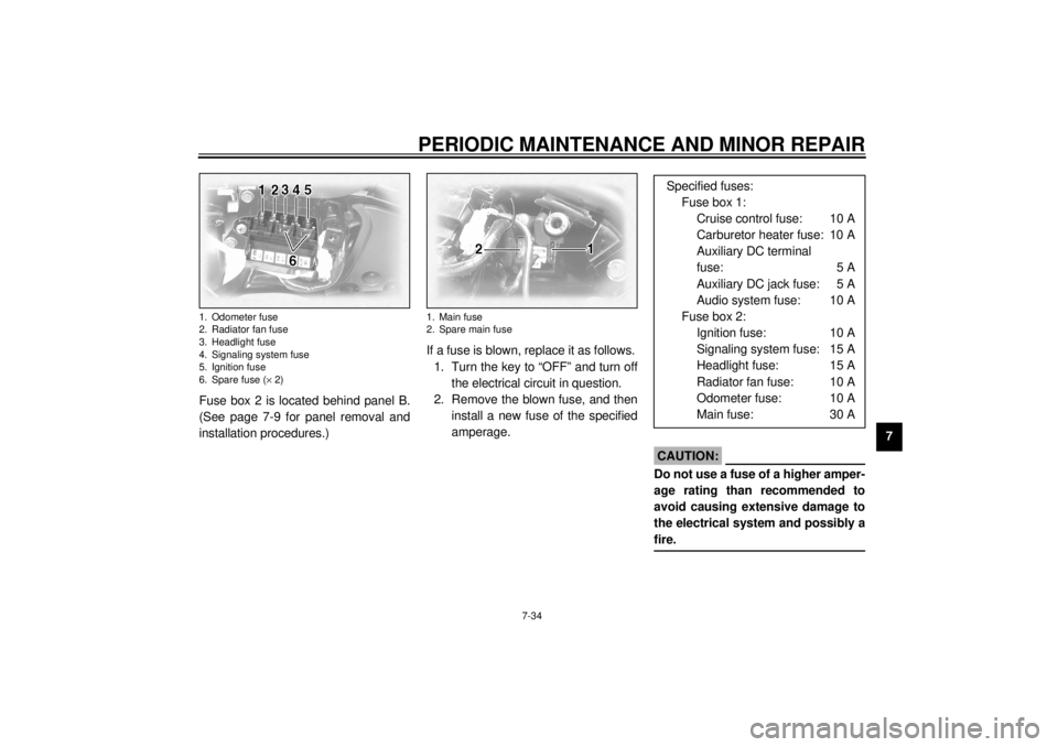
7 Fuse box 2 is located behind panel B.
(See page 7-9 for panel removal and
installation procedures.)If a fuse is blown, replace it as follows.
1. Turn the key to “OFF” and turn off
the electrical circuit in question.
2. Remove the blown fuse, and then
install a new fuse of the specified
amperage.
EC000103
CAUTION:@ Do not use a fuse of a higher amper-
age rating than recommended to
avoid causing extensive damage to
the electrical system and possibly a
fire. @
1. Odometer fuse
2. Radiator fan fuse
3. Headlight fuse
4. Signaling system fuse
5. Ignition fuse
6. Spare fuse (´ 2)
1. Main fuse
2. Spare main fuse
Specified fuses:
Fuse box 1:
Cruise control fuse: 10 A
Carburetor heater fuse: 10 A
Auxiliary DC terminal
fuse: 5 A
Auxiliary DC jack fuse: 5 A
Audio system fuse: 10 A
Fuse box 2:
Ignition fuse: 10 A
Signaling system fuse: 15 A
Headlight fuse: 15 A
Radiator fan fuse: 10 A
Odometer fuse: 10 A
Main fuse: 30 A
E_5jc.book Page 34 Monday, January 22, 2001 12:12 PM
Page 109 of 132

PERIODIC MAINTENANCE AND MINOR REPAIR
7-36
7
EC000105
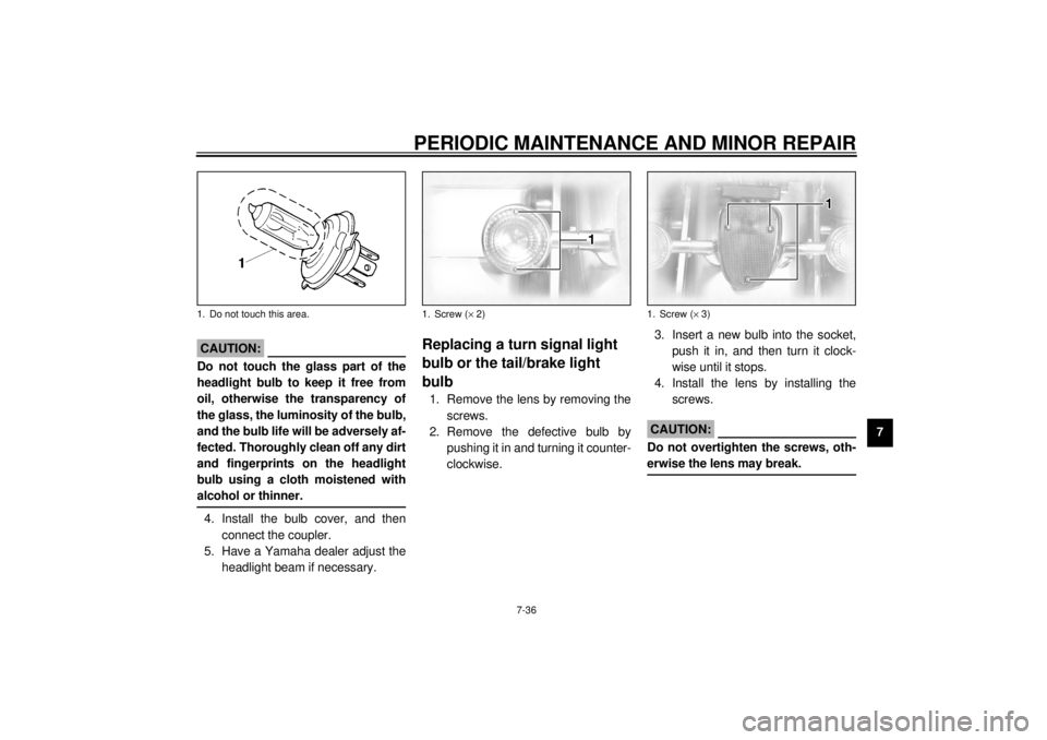
CAUTION:@ Do not touch the glass part of the
headlight bulb to keep it free from
oil, otherwise the transparency of
the glass, the luminosity of the bulb,
and the bulb life will be adversely af-
fected. Thoroughly clean off any dirt
and fingerprints on the headlight
bulb using a cloth moistened with
alcohol or thinner. @4. Install the bulb cover, and then
connect the coupler.
5. Have a Yamaha dealer adjust the
headlight beam if necessary.
EAU00855
Replacing a turn signal light
bulb or the tail/brake light
bulb 1. Remove the lens by removing the
screws.
2. Remove the defective bulb by
pushing it in and turning it counter-
clockwise.3. Insert a new bulb into the socket,
push it in, and then turn it clock-
wise until it stops.
4. Install the lens by installing the
screws.
EC000108
CAUTION:@ Do not overtighten the screws, oth-
erwise the lens may break. @
1. Do not touch this area.
1. Screw (´ 2)
1. Screw (´ 3)
E_5jc.book Page 36 Monday, January 22, 2001 12:12 PM
Page 123 of 132

SPECIFICATIONS
9-4
9
Bulb voltage, wattage ´ quantity
Headlight 12 V, 60/55 W ´ 1
Tail/brake light 12 V, 5/21 W ´ 1
Turn signal light 12 V, 21 W ´ 4
Auxiliary light 12 V, 4 W ´ 1
License light 12 V, 5 W ´ 2
Neutral indicator light 12 V, 1.7 W ´ 1
High beam indicator light 12 V, 1.7 W ´ 1
Oil level warning light 12 V, 1.7 W ´ 1
Turn signal indicator light 12 V, 1.7 W ´ 2
Fuel level warning light 14 V, 3 W ´ 1
Coolant temperature warning
light 12 V, 1.7 W ´ 1
Engine trouble warning light 12 V, 1.7 W ´ 1
Overdrive indicator light 12 V, 1.7 W ´ 1
Cruise control “SET” indicator
light 12 V, 1.7 W ´ 1
Cruise control “RES” indicator
light 12 V, 1.7 W ´ 1
Cruise control “ON” indicator
light 12 V, 1.7 W ´ 1Audio system amplifier
Output power
Speaker 14 W ´ 4
Headset 1 W ´ 2
Auto-volume range 5 steps
Output impedance
Speaker 4 W
Headset 8–16 W
Fuses
Main fuse 30 A
Headlight fuse 15 A
Signaling system fuse 15 A
Ignition fuse 10 A
Radiator fan fuse 10 A
Odometer fuse 10 A
Cruise control fuse 10 A
Carburetor heater fuse 10 A
Audio system fuse 10 A
Auxiliary DC jack fuse 5 A
Auxiliary DC terminal fuse 5 A
E_5jc.book Page 4 Monday, January 22, 2001 12:12 PM