Page 20 of 132

INSTRUMENT AND CONTROL FUNCTIONS
3-5
3
EAU03565
Speedometer unit The speedometer unit is equipped with
the following:l
a digital speedometer (which
shows riding speed)
l
an odometer (which shows the to-
tal distance traveled)
l
two tripmeters (which show the
distance traveled since they were
last set to zero)
l
a fuel reserve tripmeter (which
shows the distance traveled on the
fuel reserve)
l
a clockOdometer and tripmeter modes
Pushing the “SELECT” button switches
the display between the odometer
mode “ODO” and the tripmeter modes
“TRIP 1” and “TRIP 2” in the following
order:
ODO
® TRIP 1
® TRIP 2
® ODO
If the fuel level warning light comes on
(see page 3-4), the odometer display
will automatically change to the fuel re-
serve tripmeter mode “TRIP F” and
start counting the distance traveled
from that point. In that case, pushing
the “SELECT” button switches the dis-
play between the various tripmeter and
odometer modes in the following order:
TRIP F
® TRIP 1
® TRIP 2
® ODO
®
TRIP FTo reset a tripmeter, select it by push-
ing the “SELECT” button, and then
push the “RESET” button. If you do not
reset the fuel reserve tripmeter manu-
ally, it will reset itself automatically and
the display will return to “TRIP 1” after
refueling and traveling 5 km.
NOTE:@ After resetting the fuel reserve tripme-
ter, the display will return to “TRIP 1”,
unless a different mode had been pre-
viously selected; in that case, the dis-
play automatically returns to the prior
mode. @Clock mode
To change the display to the clock
mode, push both the “SELECT” and
“RESET” buttons.
To change the display back to the
odometer modes, push the “SELECT”
button.
1. Speedometer
2. Odometer/tripmeters/clock
3. “RESET” button
4. “SELECT” buttonE_5jc.book Page 5 Monday, January 22, 2001 12:12 PM
Page 27 of 132

INSTRUMENT AND CONTROL FUNCTIONS
3-12
3 2. Turn the key counterclockwise to
the original position, remove it,
and then close the lock cover.
NOTE:@ The fuel tank cap cannot be installed
unless the key is in the lock. In addition,
the key cannot be removed if the cap is
not properly installed and locked. @
EW000024
WARNING
@ Make sure that the fuel tank cap is
properly installed before riding. @
EAU03753
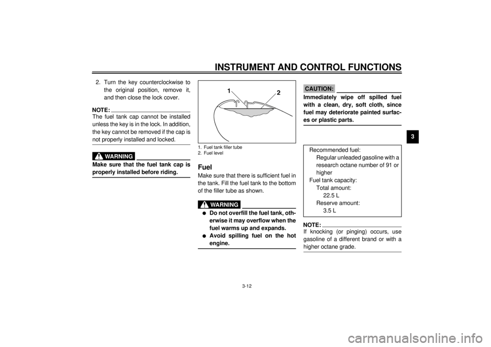
Fuel Make sure that there is sufficient fuel in
the tank. Fill the fuel tank to the bottom
of the filler tube as shown.
EW000130
WARNING
_ l
Do not overfill the fuel tank, oth-
erwise it may overflow when the
fuel warms up and expands.
l
Avoid spilling fuel on the hot
engine.
_
EAU00185
CAUTION:_ Immediately wipe off spilled fuel
with a clean, dry, soft cloth, since
fuel may deteriorate painted surfac-
es or plastic parts. _
EAU00191
NOTE:_ If knocking (or pinging) occurs, use
gasoline of a different brand or with a
higher octane grade. _
1. Fuel tank filler tube
2. Fuel level
Recommended fuel:
Regular unleaded gasoline with a
research octane number of 91 or
higher
Fuel tank capacity:
Total amount:
22.5 L
Reserve amount:
3.5 L
E_5jc.book Page 12 Monday, January 22, 2001 12:12 PM
Page 29 of 132

INSTRUMENT AND CONTROL FUNCTIONS
3-14
3
RES
This indicates reserve. With the fuel
cock lever in this position, the fuel re-
serve is made available. Turn the fuel
cock lever to this position if you run out
of fuel while riding. When this occurs,
refuel as soon as possible and be sure
to turn the fuel cock lever back to “ON”!
EAU04038
Starter (choke) knob “ ” Starting a cold engine requires a richer
air-fuel mixture, which is supplied by
the starter (choke).
Move the knob in direction
a to turn on
the starter (choke).
Move the knob in direction
b to turn off
the starter (choke).
EAU03372
Locking the steering with a
padlock In addition to the main switch/steering
lock, there are brackets on the right
side of the steering head pipe for lock-
ing the steering with a padlock. To do
so, turn the handlebar until the holes in
the two brackets are aligned, and then
lock the steering with a suitable pad-
lock.
RES: reserve position
1. Starter (choke) knob “ ”
E_5jc.book Page 14 Monday, January 22, 2001 12:12 PM
Page 121 of 132

SPECIFICATIONS
9-2
9
Final gear oil
Type SAE80 API “GL-4” hypoid gear
oil
Quantity 0.2 L
Cooling system capacity
(total amount)
3.5 L
Air filterDry type element
Fuel
Type Regular unleaded gasoline
Fuel tank capacity 22.5 L
Fuel reserve amount 3.5 L
Carburetor
Manufacturer MIKUNI
Model ´ quantity BDSR32 ´ 4
Spark plug
Manufacturer/model NGK / DPR8EA-9 or
DENSO / X24EPR-U9
Gap 0.8–0.9 mm
Clutch typeWet, multiple-disc
Transmission
Primary reduction system Spur gear
Primary reduction ratio 1.776
Secondary reduction system Shaft drive
Secondary reduction ratio 2.567
Transmission type Constant-mesh, 5-speedOperation Left foot
Gear ratio
1st 2.529
2nd 1.632
3rd 1.200
4th 0.960
5th 0.786
Chassis
Frame type Double cradle
Caster angle 29.17°
Trail 152 mm
Tire
Front
Type Tubeless tire
Size 150/80-16 71H
Manufacturer/
model Dunlop / D404F
Bridgestone / G705
Rear
Type Tubeless tire
Size 150/90B15M/C 74H
Manufacturer/
model Dunlop / D404
Bridgestone / G702
E_5jc.book Page 2 Monday, January 22, 2001 12:12 PM