2001 YAMAHA XVZ1300TF key battery
[x] Cancel search: key batteryPage 16 of 132

3-1
3
EAU00027
3-INSTRUMENT AND CONTROL FUNCTIONS
EAU00029
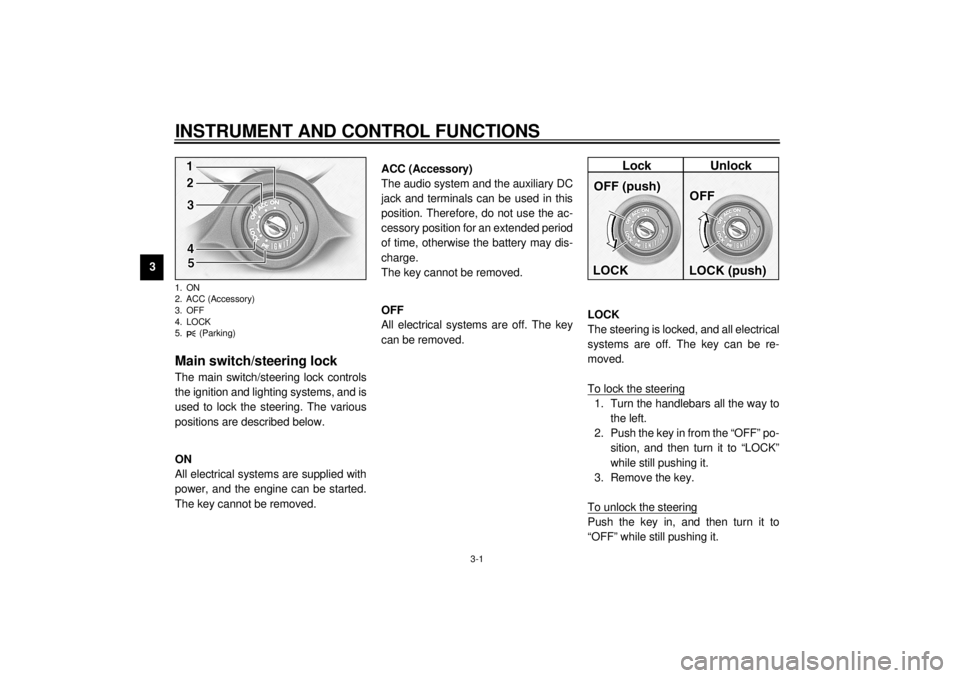
Main switch/steering lock The main switch/steering lock controls
the ignition and lighting systems, and is
used to lock the steering. The various
positions are described below.
EAU00036
ON
All electrical systems are supplied with
power, and the engine can be started.
The key cannot be removed.
EAU01842
ACC (Accessory)
The audio system and the auxiliary DC
jack and terminals can be used in this
position. Therefore, do not use the ac-
cessory position for an extended period
of time, otherwise the battery may dis-
charge.
The key cannot be removed.
EAU00038
OFF
All electrical systems are off. The key
can be removed.
EAU00040
LOCK
The steering is locked, and all electrical
systems are off. The key can be re-
moved.
To lock the steering1. Turn the handlebars all the way to
the left.
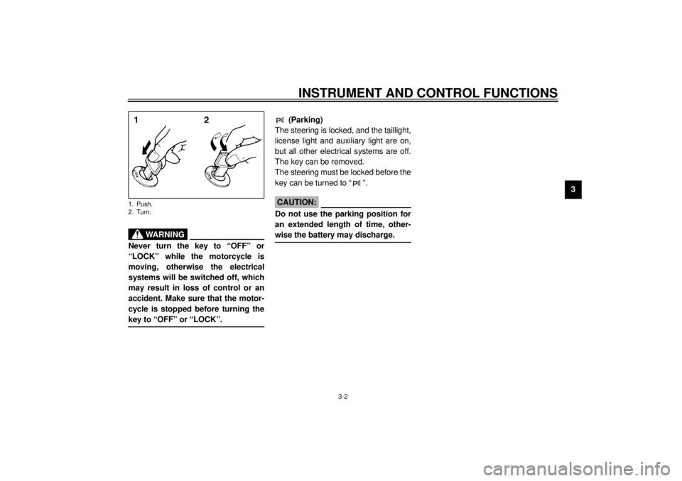
2. Push the key in from the “OFF” po-
sition, and then turn it to “LOCK”
while still pushing it.
3. Remove the key.
To unlock the steeringPush the key in, and then turn it to
“OFF” while still pushing it.
1. ON
2. ACC (Accessory)
3. OFF
4. LOCK
5. (Parking)E_5jc.book Page 1 Monday, January 22, 2001 12:12 PM
Page 17 of 132

INSTRUMENT AND CONTROL FUNCTIONS
3-2
3
EW000016
WARNING
@ Never turn the key to “OFF” or
“LOCK” while the motorcycle is
moving, otherwise the electrical
systems will be switched off, which
may result in loss of control or an
accident. Make sure that the motor-
cycle is stopped before turning the
key to “OFF” or “LOCK”. @1. Push.
2. Turn.
EAU01861
(Parking)
The steering is locked, and the taillight,
license light and auxiliary light are on,
but all other electrical systems are off.
The key can be removed.
The steering must be locked before the
key can be turned to “ ”.
ECA00043
CAUTION:_ Do not use the parking position for
an extended length of time, other-
wise the battery may discharge. _
E_5jc.book Page 2 Monday, January 22, 2001 12:12 PM
Page 39 of 132

INSTRUMENT AND CONTROL FUNCTIONS
3-24
3
EAU01788
Auxiliary DC jack and
terminals 12-V accessories connected to the
auxiliary DC jack at the front and auxil-
iary DC terminals under the rider seat
can be used when the key is in the
“ACC” or “ON” position.
ECA00044
CAUTION:@ The accessories connected to the
auxiliary DC jack and terminals
should not be used with the engine
turned off, and their combined load
must never exceed 5 A or 60 W, oth-
erwise the battery may discharge. @
EWA00017
WARNING
@ To prevent electrical shock or short-
circuiting, make sure that the caps
are installed when the auxiliary DC
jack and terminals are not being
used. @
1. Auxiliary DC jack
1. Auxiliary DC terminal
E_5jc.book Page 24 Monday, January 22, 2001 12:12 PM
Page 67 of 132

OPERATION AND IMPORTANT RIDING POINTS
6-2
6 1. Turn the fuel cock lever to “ON”.
2. Turn the key to “ON” and make
sure that the engine stop switch is
set to “ ”.
EC000035
CAUTION:_ If the fuel level warning light comes
on, check the fuel level, and, if nec-
essary, refuel as soon as possible. _3. Shift the transmission into the neu-
tral position.
NOTE:_ When the transmission is in the neutral
position, the neutral indicator light
should be on, otherwise have a
Yamaha dealer check the electrical cir-
cuit. _
4. Turn the starter (choke) on and
completely close the throttle. (See
page 3-14 for starter (choke) oper-
ation.)
5. Start the engine by pushing the
start switch.NOTE:_ If the engine fails to start, release the
start switch, wait a few seconds, and
then try again. Each starting attempt
should be as short as possible to pre-
serve the battery. Do not crank the en-
gine more than 10 seconds on any one
attempt. _
E_5jc.book Page 2 Monday, January 22, 2001 12:12 PM
Page 128 of 132

11-INDEXAAir filter elements, cleaning .................... 7-17
Anti-theft alarm ........................................3-8
Audio settings (basic) ...............................4-5
Audio settings (modes) ............................4-5
Audio system parts, location of................4-1
Auxiliary audio source ............................ 4-18
Auxiliary DC jack and terminals.............. 3-24BBattery ................................................... 7-32
Brake and clutch fluid levels,
checking .............................................. 7-28
Brake and clutch fluids, changing........... 7-29
Brake and clutch levers, checking and
lubricating ............................................ 7-30
Brake and shift pedals, checking and
lubricating ............................................ 7-29
Brake lever............................................. 3-11
Brake lever free play, adjusting .............. 7-25
Brake light switch (rear), adjusting ......... 7-26
Brake pads, checking............................. 7-27
Brake pedal............................................ 3-11
Brake pedal position, adjusting .............. 7-26CCarburetors, adjusting............................ 7-19
Care.........................................................8-1
Cassette deck operation ..........................4-9
CD changer operation ............................ 4-17
Clutch lever ............................................ 3-10
Clutch lever free play ............................. 7-25
Conversion table ......................................9-5
Coolant level, checking .......................... 7-15
Coolant temperature warning light ........... 3-4
Cowlings and panels, removing and
installing................................................ 7-6
Cruise control indicator lights ................... 3-4
Cruise control switches .......................... 3-10
Cruise control system .............................. 3-6DDimmer switch ......................................... 3-9EEngine break-in ....................................... 6-5
Engine oil and oil filter cartridge ............. 7-12
Engine stop switch................................... 3-9
Engine trouble warning light .................... 3-3FFinal gear oil .......................................... 7-15
Front fork, adjusting ............................... 3-19
Front fork, checking ............................... 7-31
Fuel ....................................................... 3-12
Fuel cock ............................................... 3-13
Fuel consumption, tips for reducing ......... 6-4
Fuel gauge .............................................. 3-8
Fuel level warning light ............................ 3-4
Fuel tank breather hose ......................... 3-13
Fuel tank cap ......................................... 3-11
Fuses, replacing .................................... 7-33HHandlebar switches ................................. 3-9
Headlight bulb, replacing ....................... 7-35
Headsets ................................................. 4-2
Helmet holders ...................................... 3-15
High beam indicator light ......................... 3-3
Horn switch ..............................................3-9IIdentification numbers ............................10-1
Idling speed, adjusting ...........................7-20
Ignition circuit cut-off system ..................3-22
Indicator and warning lights......................3-3KKey identification number .......................10-1LLicense plate light bulb, replacing...........7-37
Light switch ..............................................3-9MMain switch/steering lock .........................3-1
Model label ............................................10-2NNeutral indicator light ...............................3-4OOil level warning light ...............................3-3
Overdrive indicator light............................3-3PParking.....................................................6-6
Part locations ...........................................2-1
Pass switch ..............................................3-9
Periodic maintenance and lubrication
chart ......................................................7-3
Pre-operation check list ............................5-1RRadio operation......................................4-12
Rider seat ..............................................3-15
E_5jc.book Page 1 Monday, January 22, 2001 12:12 PM