Page 33 of 132
INSTRUMENT AND CONTROL FUNCTIONS
3-18
3
2. Fold the travel trunk lid up, and
then release it so that it will rest in
place as shown.
ECA00029
CAUTION:@ Do not apply excessive pressure on
the travel trunk lid when it is open. @
To close the travel trunk1. Fold the travel trunk lid up com-
pletely, and then fold it down.
NOTE:Push both sides of the lid down so that
both latches snap into place. @2. Turn the key clockwise, and then
remove it.
ECA00030
CAUTION:@ To avoid locking the key in, never
lock either side case or the travel
trunk and remove the key from the
lock before closing the lid. @
1. Travel trunk lid resting in opened position
2. Storage pouch
E_5jc.book Page 18 Monday, January 22, 2001 12:12 PM
Page 34 of 132

INSTRUMENT AND CONTROL FUNCTIONS
3-19
3
EAU03719
Adjusting the front fork This front fork is equipped with air
valves for adjusting the spring rate.
EW000035
WARNING
_ Always adjust both fork legs equal-
ly, otherwise poor handling and loss
of stability may result. _Adjust the spring rate as follows.
1. Place the motorcycle on the side-
stand.NOTE:_ When checking and adjusting the air
pressure, there should be no weight on
the motorcycle. _
2. Remove the air valve cap from
each fork leg.
3. Check the air pressure in each
fork leg with the air pressure
gauge included in the owner’s tool
kit.
4. To increase the spring rate and
thereby harden the suspension,
increase the air pressure with an
air pump. To decrease the spring
rate and thereby soften the sus-
pension, decrease the air pres-
sure by pushing each valve stem
down.
EC000012
CAUTION:_ Never exceed the maximum air pres-
sure, otherwise the front fork oil
seals may become damaged. _5. Securely install the air valve caps.
1. Front fork air valve cap
Spring rate:
Minimum (soft):
Air pressure =
0 kPa (0 kgf/cm
2, 0 bar)
Standard:
Air pressure =
0 kPa (0 kgf/cm2, 0 bar)
Maximum (hard):
Air pressure =
50 kPa (0.5 kgf/cm
2, 0.5 bar)
E_5jc.book Page 19 Monday, January 22, 2001 12:12 PM
Page 35 of 132

INSTRUMENT AND CONTROL FUNCTIONS
3-20
3
EAU03721
Adjusting the shock absorber
assembly This shock absorber assembly is
equipped with an air valve for adjusting
the spring rate.
EC000015
CAUTION:_ Never attempt to turn an adjusting
mechanism beyond the maximum
or minimum settings. _Adjust the spring rate as follows.
1. Place the motorcycle on the
sidestand.NOTE:_ When checking and adjusting the air
pressure, there should be no weight on
the motorcycle. _
2. Remove the air valve cap.
3. Check the air pressure with the air
pressure gauge included in the
owner’s tool kit.
4. To increase the spring rate and
thereby harden the suspension, in-
crease the air pressure with an air
pump. To decrease the spring rate
and thereby soften the suspen-
sion, decrease the air pressure by
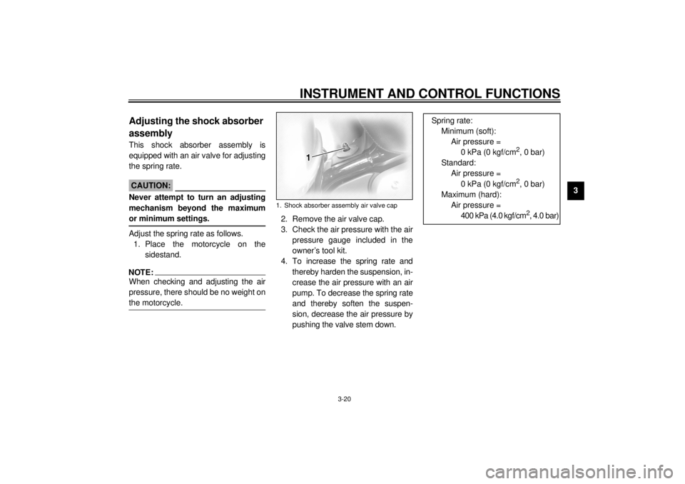
pushing the valve stem down.1. Shock absorber assembly air valve cap
Spring rate:
Minimum (soft):
Air pressure =
0 kPa (0 kgf/cm
2, 0 bar)
Standard:
Air pressure =
0 kPa (0 kgf/cm2, 0 bar)
Maximum (hard):
Air pressure =
400 kPa (4.0 kgf/cm2, 4.0 bar)
E_5jc.book Page 20 Monday, January 22, 2001 12:12 PM
Page 36 of 132

INSTRUMENT AND CONTROL FUNCTIONS
3-21
3
ECA00050
CAUTION:_ Never exceed the maximum air pres-
sure, otherwise the oil seal may be-
come damaged. _5. Securely install the air valve cap.
EAU00330
Sidestand The sidestand is located on the left side
of the frame. Raise the sidestand or
lower it with your foot while holding the
motorcycle upright.NOTE:@ The built-in sidestand switch is part of
the ignition circuit cut-off system, which
cuts the ignition in certain situations.
(See further down for an explanation of
the ignition circuit cut-off system.) @
EW000044
WARNING
@ The motorcycle must not be ridden
with the sidestand down, or if the
sidestand cannot be properly
moved up (or does not stay up), oth-
erwise the sidestand could contact
the ground and distract the opera-
tor, resulting in a possible loss of
control. Yamaha’s ignition circuit
cut-off system has been designed to
assist the operator in fulfilling the
responsibility of raising the side-
stand before starting off. Therefore,
check this system regularly as de-
scribed below and have a Yamaha
dealer repair it if it does not function
properly. @
E_5jc.book Page 21 Monday, January 22, 2001 12:12 PM
Page 37 of 132
INSTRUMENT AND CONTROL FUNCTIONS
3-22
3
EAU03720
Ignition circuit cut-off system The ignition circuit cut-off system (com-
prising the sidestand switch, clutch
switch and neutral switch) has the fol-
lowing functions.l
It prevents starting when the trans-
mission is in gear and the side-
stand is up, but the clutch lever is
not pulled.
l
It prevents starting when the trans-
mission is in gear and the clutch
lever is pulled, but the sidestand is
still down.
l
It cuts the running engine when
the transmission is in gear and the
sidestand is moved down.
Periodically check the operation of the
ignition circuit cut-off system according
to the following procedure.
EW000045
WARNING
_ If a malfunction is noted, have a
Yamaha dealer check the system
before riding. _
E_5jc.book Page 22 Monday, January 22, 2001 12:12 PM
Page 38 of 132

INSTRUMENT AND CONTROL FUNCTIONS
3-23
3
CD-01E
With the engine turned off:
1. Move the sidestand down.
2. Make sure that the engine stop switch is set to “ ”.
3. Turn the key to “ON”.
4. Shift the transmission into the neutral position.
5. Push the start switch.
Does the engine start?
The neutral switch may be defective.
The motorcycle should not be ridden until
checked by a Yamaha dealer.
With the engine still running:
6. Move the sidestand up.
7. Keep the clutch lever pulled.
8. Shift the transmission into gear.
9. Move the sidestand down.
Does the engine stall?After the engine has stalled:
10. Move the sidestand up.
11. Keep the clutch lever pulled.
12. Push the start switch.
Does the engine start?
The sidestand switch may be defective.
The motorcycle should not be ridden until
checked by a Yamaha dealer.The clutch switch may be defective.
The motorcycle should not be ridden until
checked by a Yamaha dealer.
NO
NOTE:This check is most reliable if performed with
a warmed-up engine.
YESYES NO
The system is OK.
The motorcycle can be ridden.
YES NO
E_5jc.book Page 23 Monday, January 22, 2001 12:12 PM
Page 39 of 132
INSTRUMENT AND CONTROL FUNCTIONS
3-24
3
EAU01788
Auxiliary DC jack and
terminals 12-V accessories connected to the
auxiliary DC jack at the front and auxil-
iary DC terminals under the rider seat
can be used when the key is in the
“ACC” or “ON” position.
ECA00044
CAUTION:@ The accessories connected to the
auxiliary DC jack and terminals
should not be used with the engine
turned off, and their combined load
must never exceed 5 A or 60 W, oth-
erwise the battery may discharge. @
EWA00017
WARNING
@ To prevent electrical shock or short-
circuiting, make sure that the caps
are installed when the auxiliary DC
jack and terminals are not being
used. @
1. Auxiliary DC jack
1. Auxiliary DC terminal
E_5jc.book Page 24 Monday, January 22, 2001 12:12 PM
Page 40 of 132
E_5jc.book Page 25 Monday, January 22, 2001 12:12 PM