Page 7 of 132
TABLE OF CONTENTS
1 GIVE SAFETY THE RIGHT OF WAY
1
2 DESCRIPTION
2
3 INSTRUMENT AND CONTROL FUNCTIONS
3
4 AUDIO SYSTEM
4
5 PRE-OPERATION CHECKS
5
6 OPERATION AND IMPORTANT RIDING POINTS
6
7 PERIODIC MAINTENANCE AND MINOR REPAIR
7
8 MOTORCYCLE CARE AND STORAGE
8
9 SPECIFICATIONS
9
10 CONSUMER INFORMATION
10
INDEX
E_5jc.book Page 1 Monday, January 22, 2001 12:12 PM
Page 14 of 132
DESCRIPTION
2-3
2
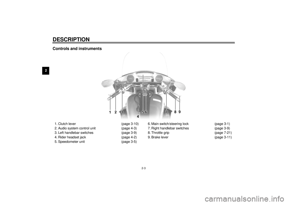
Controls and instruments1. Clutch lever (page 3-10)
2. Audio system control unit (page 4-3)
3. Left handlebar switches (page 3-9)
4. Rider headset jack (page 4-2)
5. Speedometer unit (page 3-5)6. Main switch/steering lock (page 3-1)
7. Right handlebar switches (page 3-9)
8. Throttle grip (page 7-21)
9. Brake lever (page 3-11)
E_5jc.book Page 3 Monday, January 22, 2001 12:12 PM
Page 16 of 132
3-1
3
EAU00027
3-INSTRUMENT AND CONTROL FUNCTIONS
EAU00029
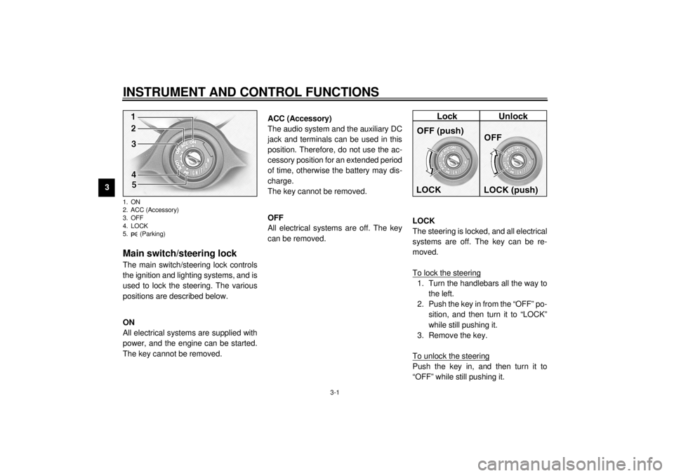
Main switch/steering lock The main switch/steering lock controls
the ignition and lighting systems, and is
used to lock the steering. The various
positions are described below.
EAU00036
ON
All electrical systems are supplied with
power, and the engine can be started.
The key cannot be removed.
EAU01842
ACC (Accessory)
The audio system and the auxiliary DC
jack and terminals can be used in this
position. Therefore, do not use the ac-
cessory position for an extended period
of time, otherwise the battery may dis-
charge.
The key cannot be removed.
EAU00038
OFF
All electrical systems are off. The key
can be removed.
EAU00040
LOCK
The steering is locked, and all electrical
systems are off. The key can be re-
moved.
To lock the steering1. Turn the handlebars all the way to
the left.
2. Push the key in from the “OFF” po-
sition, and then turn it to “LOCK”
while still pushing it.
3. Remove the key.
To unlock the steeringPush the key in, and then turn it to
“OFF” while still pushing it.
1. ON
2. ACC (Accessory)
3. OFF
4. LOCK
5. (Parking)E_5jc.book Page 1 Monday, January 22, 2001 12:12 PM
Page 41 of 132
AUDIO SYSTEM
4
Location of parts ............................................................................... 4-1
Headsets (optional) ........................................................................... 4-2
Control unit ........................................................................................ 4-3
Making basic settings ........................................................................ 4-5
Making mode settings ....................................................................... 4-5
Cassette deck operation .................................................................... 4-9
Radio operation ............................................................................... 4-12
Optional CD changer operation ....................................................... 4-17
Auxiliary audio source operation ..................................................... 4-18
E_5jc.book Page 1 Monday, January 22, 2001 12:12 PM
Page 42 of 132
4-1
4
EAU03968*
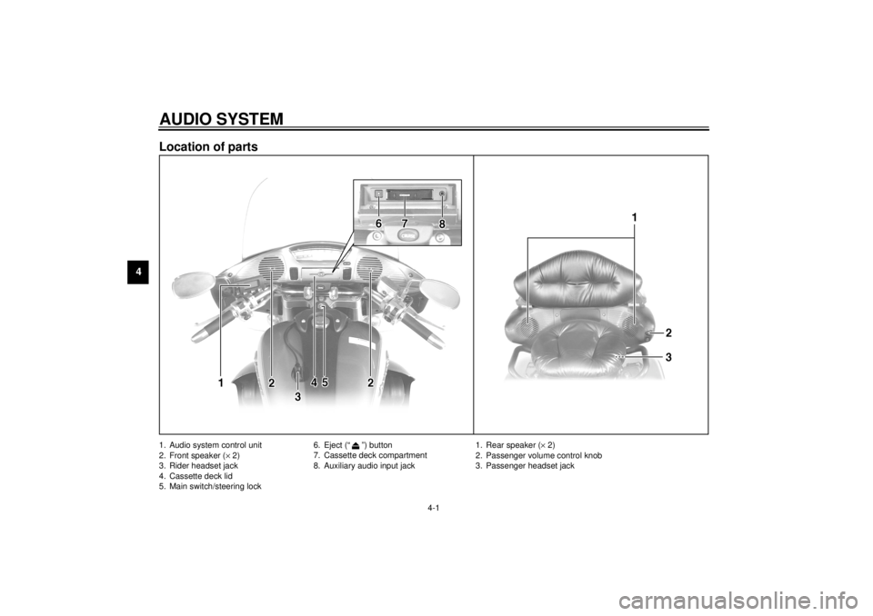
4-AUDIO SYSTEMLocation of parts 1. Audio system control unit
2. Front speaker (´ 2)
3. Rider headset jack
4. Cassette deck lid
5. Main switch/steering lock6. Eject (“ ”) button
7. Cassette deck compartment
8. Auxiliary audio input jack
1. Rear speaker (´ 2)
2. Passenger volume control knob
3. Passenger headset jack
E_5jc.book Page 1 Monday, January 22, 2001 12:12 PM
Page 43 of 132
AUDIO SYSTEM
4-2
4
WARNING
_ l
It is dangerous to operate the
audio system controls while
riding. Never take your hands
off the handlebars while riding.
l
Keep the volume at a low
enough level to be aware of traf-
fic conditions and ensure
safety.
_CAUTION:_ l
Do not use the audio system for
a long period of time when the
engine is not running as the bat-
tery may discharge.
l
The control unit, cassette deck
and speakers are water-resis-
tant; however, it is good prac-
tice to cover them with a plastic
bag when washing the motor-
cycle.
l
When cleaning the control unit
display, use a neutral detergent.
Never use strong abrasive
cleaning products, fuel (gaso-
line), thinner, etc.
_
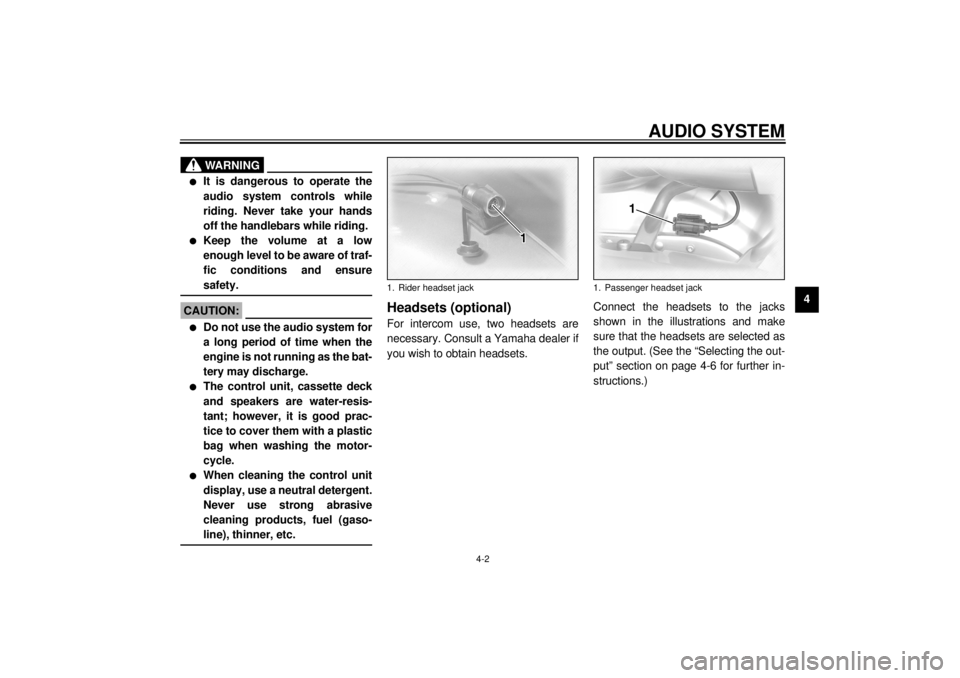
Headsets (optional) For intercom use, two headsets are
necessary. Consult a Yamaha dealer if
you wish to obtain headsets.Connect the headsets to the jacks
shown in the illustrations and make
sure that the headsets are selected as
the output. (See the “Selecting the out-
put” section on page 4-6 for further in-
structions.)1. Rider headset jack
1. Passenger headset jack
E_5jc.book Page 2 Monday, January 22, 2001 12:12 PM
Page 44 of 132
AUDIO SYSTEM
4-3
4
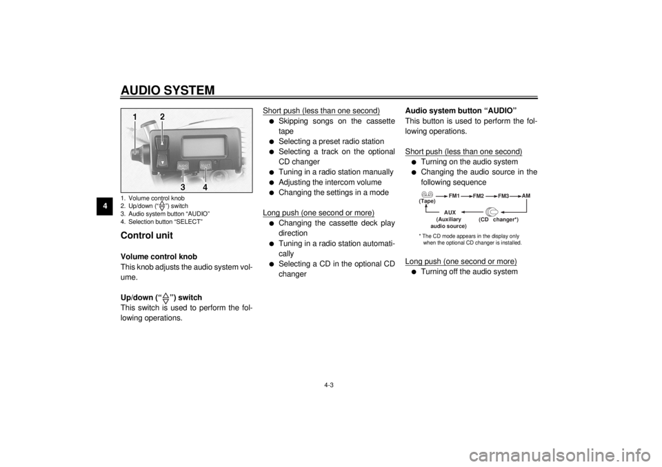
Control unit Volume control knob
This knob adjusts the audio system vol-
ume.
Up/down (“ ”) switch
This switch is used to perform the fol-
lowing operations.Short push (less than one second)
l
Skipping songs on the cassette
tape
l
Selecting a preset radio station
l
Selecting a track on the optional
CD changer
l
Tuning in a radio station manually
l
Adjusting the intercom volume
l
Changing the settings in a mode
Long push (one second or more)
l
Changing the cassette deck play
direction
l
Tuning in a radio station automati-
cally
l
Selecting a CD in the optional CD
changerAudio system button “AUDIO”
This button is used to perform the fol-
lowing operations.
Short push (less than one second)
l
Turning on the audio system
l
Changing the audio source in the
following sequence
Long push (one second or more)
l
Turning off the audio system
1. Volume control knob
2. Up/down (“ ”) switch
3. Audio system button “AUDIO”
4. Selection button “SELECT”
(Tape)FM1
FM2
FM3AM
AUX
(CD changer
*)
(Auxiliary
audio source)
* The CD mode appears in the display only
when the optional CD changer is installed.
E_5jc.book Page 3 Monday, January 22, 2001 12:12 PM
Page 45 of 132
AUDIO SYSTEM
4-4
4 Selection button “SELECT”
This button is used to perform the fol-
lowing operations.
Short push (less than two seconds)
l
Changing modes in the following
sequence
l
Programming preset radio stations
Long push (two seconds or more)
l
Selecting the preset radio station
programming mode
(Output)BASS TREBFAD
(Auto
volume)
(Intercom
volume)
Radio SP/HS
(Treble)
frequency(Fade )
1
2IC
AV
1
2This mode does not appear in the display when
the headsets are selected as the output.
This mode appears in the display only when one
of the radio frequency bands is selected as the au- dio source.
E_5jc.book Page 4 Monday, January 22, 2001 12:12 PM