2001 YAMAHA XVZ1300TF brake light
[x] Cancel search: brake lightPage 12 of 132
2-1
2
EAU00026
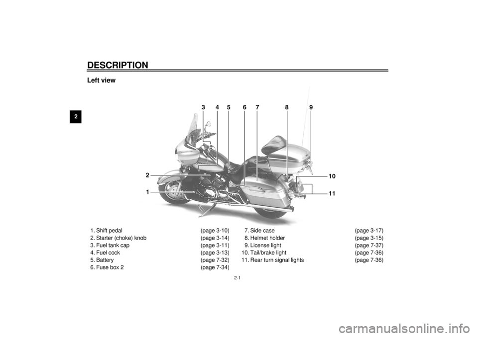
2-DESCRIPTION Left view1. Shift pedal (page 3-10)
2. Starter (choke) knob (page 3-14)
3. Fuel tank cap (page 3-11)
4. Fuel cock (page 3-13)
5. Battery (page 7-32)
6. Fuse box 2 (page 7-34)7. Side case (page 3-17)
8. Helmet holder (page 3-15)
9. License light (page 7-37)
10. Tail/brake light (page 7-36)
11. Rear turn signal lights (page 7-36)
E_5jc.book Page 1 Monday, January 22, 2001 12:12 PM
Page 13 of 132

DESCRIPTION
2-2
2
Right view12. Muffler
13. Owner’s tool kit (page 7-1)
14. Helmet holder (page 3-15)
15. Travel trunk (page 3-17)
16. Passenger seat
17. Shock absorber assembly air valve (page 3-20)
18. Rider seat (page 3-15)
19. Fuel tank (page 3-12)
20. Front fork air valve (page 3-19)21. Headlight (page 7-35)
22. Front turn signal lights (page 7-36)
23. Fuse box 1 (page 7-33)
24. Brake pedal (page 3-11)
25. Engine oil level check window (page 7-12)
26. Rider footrest
27. Coolant reservoir (page 7-15)
28. Passenger footrest
E_5jc.book Page 2 Monday, January 22, 2001 12:12 PM
Page 15 of 132
3
INSTRUMENT AND CONTROL FUNCTIONS
Main switch/steering lock ..................................... 3-1
Indicator and warning lights ................................ 3-3
Speedometer unit ................................................ 3-5
Cruise control system ........................................... 3-6
Fuel gauge ........................................................... 3-8
Anti-theft alarm (optional) .................................... 3-8
Handlebar switches ............................................. 3-9
Clutch lever ........................................................ 3-10
Shift pedal .......................................................... 3-10
Brake lever ......................................................... 3-11
Brake pedal ........................................................ 3-11
Fuel tank cap ..................................................... 3-11
Fuel .................................................................... 3-12Fuel tank breather hose .................................... 3-13
Fuel cock ........................................................... 3-13
Starter (choke) knob ......................................... 3-14
Locking the steering with a padlock .................. 3-14
Rider seat .......................................................... 3-15
Helmet holders .................................................. 3-15
Side cases and travel trunk ............................... 3-16
Adjusting the front fork ...................................... 3-19
Adjusting the shock absorber assembly ............ 3-20
Sidestand .......................................................... 3-21
Ignition circuit cut-off system ............................. 3-22
Auxiliary DC jack and terminals ........................ 3-24
E_5jc.book Page 1 Monday, January 22, 2001 12:12 PM
Page 22 of 132

INSTRUMENT AND CONTROL FUNCTIONS
3-7
3
2. Press the “SET/DEC” (set/decel-
erate) side of the cruise control
switch to activate the cruise con-
trol system. The “SET” indicator
light comes on.
3. Set the desired traveling speed as
follows. Press the “RES/ACC” (re-
sume/accelerate) side of the
cruise control switch to increase
the set speed or the “SET/DEC”
side to decrease the speed.
NOTE:_ Pressing the cruise control switch once
will change the speed in increments of
1.6 km/h. Holding the cruise control
switch down will increase or decrease
the speed continuously until the switch
is released. _The traveling speed can be set to a
maximum of 130 km/h and a minimum
of 50 km/h.
When the cruise control system is acti-
vated and the throttle grip is turned to
increase the speed by up to 8 km/h, the
cruise control system will return to theset speed after the throttle grip is re-
leased. However, if the speed is in-
creased by more than 8 km/h, the
cruise control system will be deactivat-
ed until the traveling speed is within
8 km/h of the set speed.
Deactivating the cruise control
system
Applying the front or rear brake or dis-
engaging the clutch will automatically
deactivate the cruise control system.
Push the “CANCEL” switch to manually
deactivate cruise control.
NOTE:_ l
When the cruise control system is
deactivated, the “RES” (resume)
indicator light will come on.
l
Traveling speed decreases as
soon as the cruise control system
is deactivated; unless the throttle
grip is turned.
_
1. Cruise control switch
2. “CANCEL” switch
1. “SET” indicator light
2. “RES” indicator light
3. “ON” indicator light
E_5jc.book Page 7 Monday, January 22, 2001 12:12 PM
Page 63 of 132

PRE-OPERATION CHECKS
5-2
5
Clutch• Check operation.
• If soft or spongy, have Yamaha dealer bleed hydraulic system.
• Check fluid level in reservoir.
• If necessary, add recommended fluid to specified level.
• Check hydraulic system for leakage.7-25, 7-28
Throttle grip• Make sure that operation is smooth.
• Lubricate throttle grip, housing and cables if necessary.
• Check free play.
• If necessary, have Yamaha dealer make adjustment.7-21
Control cables• Make sure that operation is smooth.
• Lubricate if necessary.—
Wheels and tires• Check for damage.
• Check tire condition and tread depth.
• Check air pressure.
• Correct if necessary.7-21–7-24
Brake and shift pedals• Make sure that operation is smooth.
• Lubricate pedal pivoting points if necessary.7-29
Brake and clutch levers• Make sure that operation is smooth.
• Lubricate lever pivoting points if necessary.7-30
Sidestand• Make sure that operation is smooth.
• Lubricate pivot if necessary.7-30
Chassis fasteners• Make sure that all nuts, bolts and screws are properly tightened.
• Tighten if necessary.—
Instruments, lights, signals
and switches• Check operation.
• Correct if necessary.—
Sidestand switch• Check operation of ignition circuit cut-off system.
• If system is defective, have Yamaha dealer check vehicle.3-21 ITEM CHECKS PAGE
E_5jc.book Page 2 Monday, January 22, 2001 12:12 PM
Page 73 of 132

7
PERIODIC MAINTENANCE AND MINOR REPAIR
Owner’s tool kit .................................................... 7-1
Periodic maintenance and lubrication chart ......... 7-3
Removing and installing cowlings and panels ..... 7-6
Checking the spark plugs .................................. 7-11
Engine oil and oil filter cartridge ........................ 7-12
Final gear oil ...................................................... 7-15
Checking the coolant level ................................. 7-15
Cleaning the air filter elements .......................... 7-17
Adjusting the carburetors ................................... 7-19
Adjusting the engine idling speed ...................... 7-20
Adjusting the throttle cable free play .................. 7-21
Adjusting the valve clearance ............................ 7-21
Tires ................................................................... 7-21
Cast wheels ....................................................... 7-24
Clutch lever free play ......................................... 7-25
Adjusting the brake lever free play ..................... 7-25
Adjusting the brake pedal position ..................... 7-26
Adjusting the rear brake light switch .................. 7-26Checking the front and rear brake pads ............ 7-27
Checking the brake and clutch fluid levels ........ 7-28
Changing the brake and clutch fluids ................ 7-29
Checking and lubricating the brake and
shift pedals ...................................................... 7-29
Checking and lubricating the brake and
clutch levers .................................................... 7-30
Checking and lubricating the sidestand ............ 7-30
Checking the front fork ...................................... 7-31
Checking the steering ....................................... 7-31
Battery ............................................................... 7-32
Replacing the fuses .......................................... 7-33
Replacing the headlight bulb ............................. 7-35
Replacing a turn signal light bulb or the
tail/brake light bulb .......................................... 7-36
Replacing the license plate light bulb ................ 7-37
Troubleshooting ................................................. 7-37
Troubleshooting charts ...................................... 7-38
E_5jc.book Page 1 Monday, January 22, 2001 12:12 PM
Page 78 of 132
PERIODIC MAINTENANCE AND MINOR REPAIR
7-5
7
EAU03892
NOTE:_ l
The air filter needs more frequent service if you are riding in unusually wet or dusty areas.
l
Hydraulic brake and clutch systems
• After disassembling the brake or clutch master cylinders, caliper cylinders or clutch release cylinder, always change
the fluid. Regularly check the brake and clutch fluid levels and fill the reservoirs as required.
• Replace the oil seals on the inner parts of the brake or clutch master cylinders, caliper cylinders and clutch release
cylinder every two years.
• Replace the brake and clutch hoses every four years or if cracked or damaged.
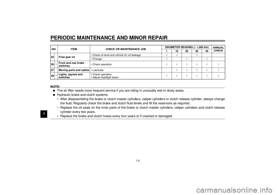
_25 Final gear oil• Check oil level and vehicle for oil leakage.ÖÖ Ö
• Change.ÖÖÖ
26
*Front and rear brake
switches• Check operation.ÖÖÖÖÖ Ö
27 Moving parts and cables• Lubricate.ÖÖÖÖ Ö
28*Lights, signals and
switches• Check operation.
• Adjust headlight beam.ÖÖÖÖÖ Ö NO. ITEM CHECK OR MAINTENANCE JOBODOMETER READING (´1,000 km)
ANNUAL
CHECK
1 10203040
E_5jc.book Page 5 Monday, January 22, 2001 12:12 PM
Page 99 of 132

PERIODIC MAINTENANCE AND MINOR REPAIR
7-26
7
EAU01746
Adjusting the brake pedal
position The top of the brake pedal should be
positioned approximately 100 mm
above the top of the footrest as shown.
Periodically check the brake pedal po-
sition and, if necessary, have a
Yamaha dealer adjust it.
EW000109
WARNING
@ A soft or spongy feeling in the brake
pedal can indicate the presence of
air in the hydraulic system. If there
is air in the hydraulic system, have a
Yamaha dealer bleed the system be-
fore operating the motorcycle. Air in
the hydraulic system will diminish
the braking performance, which
may result in loss of control and an
accident. @
EAU01799
Adjusting the rear brake light
switch The rear brake light switch, which is ac-
tivated by the brake pedal, is properly
adjusted when the brake light comes
on just before braking takes effect.
Since the brake light switch is a compo-
nent of the cruise control system, it
must be adjusted by a Yamaha dealer,
who has the necessary professional
knowledge and experience.
a. Distance between brake pedal and footrest
E_5jc.book Page 26 Monday, January 22, 2001 12:12 PM