2001 YAMAHA XVZ1300TF trunk
[x] Cancel search: trunkPage 13 of 132

DESCRIPTION
2-2
2
Right view12. Muffler
13. Owner’s tool kit (page 7-1)
14. Helmet holder (page 3-15)
15. Travel trunk (page 3-17)
16. Passenger seat
17. Shock absorber assembly air valve (page 3-20)
18. Rider seat (page 3-15)
19. Fuel tank (page 3-12)
20. Front fork air valve (page 3-19)21. Headlight (page 7-35)
22. Front turn signal lights (page 7-36)
23. Fuse box 1 (page 7-33)
24. Brake pedal (page 3-11)
25. Engine oil level check window (page 7-12)
26. Rider footrest
27. Coolant reservoir (page 7-15)
28. Passenger footrest
E_5jc.book Page 2 Monday, January 22, 2001 12:12 PM
Page 15 of 132
3
INSTRUMENT AND CONTROL FUNCTIONS
Main switch/steering lock ..................................... 3-1
Indicator and warning lights ................................ 3-3
Speedometer unit ................................................ 3-5
Cruise control system ........................................... 3-6
Fuel gauge ........................................................... 3-8
Anti-theft alarm (optional) .................................... 3-8
Handlebar switches ............................................. 3-9
Clutch lever ........................................................ 3-10
Shift pedal .......................................................... 3-10
Brake lever ......................................................... 3-11
Brake pedal ........................................................ 3-11
Fuel tank cap ..................................................... 3-11
Fuel .................................................................... 3-12Fuel tank breather hose .................................... 3-13
Fuel cock ........................................................... 3-13
Starter (choke) knob ......................................... 3-14
Locking the steering with a padlock .................. 3-14
Rider seat .......................................................... 3-15
Helmet holders .................................................. 3-15
Side cases and travel trunk ............................... 3-16
Adjusting the front fork ...................................... 3-19
Adjusting the shock absorber assembly ............ 3-20
Sidestand .......................................................... 3-21
Ignition circuit cut-off system ............................. 3-22
Auxiliary DC jack and terminals ........................ 3-24
E_5jc.book Page 1 Monday, January 22, 2001 12:12 PM
Page 31 of 132
INSTRUMENT AND CONTROL FUNCTIONS
3-16
3
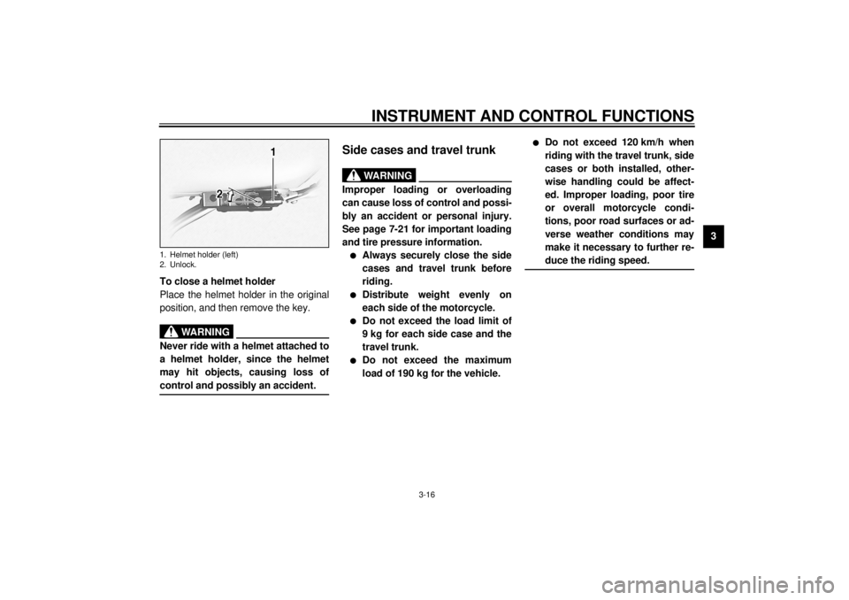
To close a helmet holder
Place the helmet holder in the original
position, and then remove the key.
EWA00015
WARNING
@ Never ride with a helmet attached to
a helmet holder, since the helmet
may hit objects, causing loss of
control and possibly an accident. @
EAU01866*
Side cases and travel trunk
EWA00021*
WARNING
@ Improper loading or overloading
can cause loss of control and possi-
bly an accident or personal injury.
See page 7-21 for important loading
and tire pressure information.l
Always securely close the side
cases and travel trunk before
riding.
l
Distribute weight evenly on
each side of the motorcycle.
l
Do not exceed the load limit of
9 kg for each side case and the
travel trunk.
l
Do not exceed the maximum
load of 190 kg for the vehicle.
l
Do not exceed 120 km/h when
riding with the travel trunk, side
cases or both installed, other-
wise handling could be affect-
ed. Improper loading, poor tire
or overall motorcycle condi-
tions, poor road surfaces or ad-
verse weather conditions may
make it necessary to further re-
duce the riding speed.
@
1. Helmet holder (left)
2. Unlock.
E_5jc.book Page 16 Monday, January 22, 2001 12:12 PM
Page 32 of 132

INSTRUMENT AND CONTROL FUNCTIONS
3-17
3
Side cases
To open a side case
1. Insert the key into the lock, turn it
counterclockwise, and then push it
in.2. Fold the side case lid up.
To close a side case
1. Fold the side case lid down.
2. Turn the key clockwise, and then
remove it.NOTE:Push both sides of the lid down so that
both latches snap into place. @
Travel trunk
To open the travel trunk1. Insert the key into the lock, turn it
counterclockwise, and then push it
in.
1. Side case lock
2. Unlock.
1. Main storage area
2. Storage pouch
1. Travel trunk lock
2. Unlock.
E_5jc.book Page 17 Monday, January 22, 2001 12:12 PM
Page 33 of 132

INSTRUMENT AND CONTROL FUNCTIONS
3-18
3
2. Fold the travel trunk lid up, and
then release it so that it will rest in
place as shown.
ECA00029
CAUTION:@ Do not apply excessive pressure on
the travel trunk lid when it is open. @
To close the travel trunk1. Fold the travel trunk lid up com-
pletely, and then fold it down.
NOTE:Push both sides of the lid down so that
both latches snap into place. @2. Turn the key clockwise, and then
remove it.
ECA00030
CAUTION:@ To avoid locking the key in, never
lock either side case or the travel
trunk and remove the key from the
lock before closing the lid. @
1. Travel trunk lid resting in opened position
2. Storage pouch
E_5jc.book Page 18 Monday, January 22, 2001 12:12 PM
Page 58 of 132
AUDIO SYSTEM
4-17
4
Optional CD changer
operation
WARNING
_ l
It is dangerous to operate the
CD changer while riding. Never
take your hands off the handle-
bars while riding.
l
Keep the volume at a low
enough level to be aware of traf-
fic conditions and ensure safe-
ty.
_An optional six-disc CD changer can be
mounted in the travel trunk. Ask a
Yamaha dealer to install the genuine
Clarion CDC635 model.Playing a CD
1. Insert up to six CDs into the CD
changer. Follow the manufactur-
er’s directions.
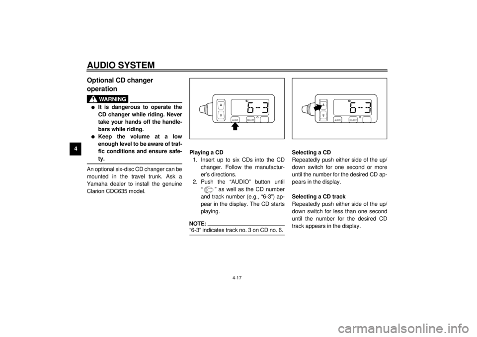
2. Push the “AUDIO” button until
“ ” as well as the CD number
and track number (e.g., “6-3”) ap-
pear in the display. The CD starts
playing.
NOTE:_ “6-3” indicates track no. 3 on CD no. 6. _
Selecting a CD
Repeatedly push either side of the up/
down switch for one second or more
until the number for the desired CD ap-
pears in the display.
Selecting a CD track
Repeatedly push either side of the up/
down switch for less than one second
until the number for the desired CD
track appears in the display.
E_5jc.book Page 17 Monday, January 22, 2001 12:12 PM
Page 115 of 132
MOTORCYCLE CARE AND STORAGE
8-2
8 thinner, fuel (gasoline), rust re-
movers or inhibitors, brake flu-
id, antifreeze or electrolyte.
l
Do not use high-pressure wash-
ers or steam-jet cleaners since
they cause water seepage and
deterioration in the following ar-
eas: seals (of wheel and swing-
arm bearings, fork and brakes),
electric components (couplers,
connectors, instruments, switch-
es, lights, audio system and
speakers), sidecases, travel
trunk, breather hoses and vents.
l
For motorcycles equipped with
a windshield: Do not use strong
cleaners or hard sponges as
they will cause dulling or
scratching. Some cleaning
compounds for plastic may
leave scratches on the wind-
shield. Test the product on a
small hidden part of the wind-
shield to make sure that it does
not leave any marks. If the wind-
shield is scratched, use a quali-
ty plastic polishing compound
after washing.
_After normal useRemove dirt with warm water, a mild
detergent, and a soft, clean sponge,
and then rinse thoroughly with clean
water. Use a toothbrush or bottlebrush
for hard-to-reach areas. Stubborn dirt
and insects will come off more easily if
the area is covered with a wet cloth for
a few minutes before cleaning.After riding in the rain, near the sea or
on salt-sprayed roadsSince sea salt or salt sprayed on roads
during winter are extremely corrosive in
combination with water, carry out the
following steps after each ride in the
rain, near the sea or on salt-sprayed
roads.NOTE:_ Salt sprayed on roads in the winter may
remain well into spring. _1. Clean the motorcycle with cold
water and a mild detergent, after
the engine has cooled down.
ECA00012
CAUTION:_ Do not use warm water since it in-
creases the corrosive action of the
salt. _2. Apply a corrosion protection spray
on all metal, including chrome-
and nickel-plated, surfaces to pre-
vent corrosion.
E_5jc.book Page 2 Monday, January 22, 2001 12:12 PM
Page 129 of 132
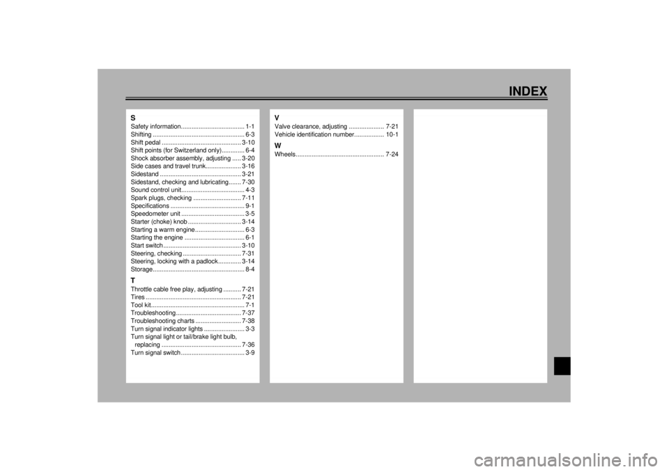
INDEX
SSafety information.................................... 1-1
Shifting .................................................... 6-3
Shift pedal ............................................. 3-10
Shift points (for Switzerland only)............. 6-4
Shock absorber assembly, adjusting ..... 3-20
Side cases and travel trunk.................... 3-16
Sidestand .............................................. 3-21
Sidestand, checking and lubricating....... 7-30
Sound control unit.................................... 4-3
Spark plugs, checking ........................... 7-11
Specifications .......................................... 9-1
Speedometer unit .................................... 3-5
Starter (choke) knob .............................. 3-14
Starting a warm engine ............................ 6-3
Starting the engine .................................. 6-1
Start switch ............................................ 3-10
Steering, checking ................................. 7-31
Steering, locking with a padlock............. 3-14
Storage.................................................... 8-4TThrottle cable free play, adjusting .......... 7-21
Tires ...................................................... 7-21
Tool kit..................................................... 7-1
Troubleshooting..................................... 7-37
Troubleshooting charts .......................... 7-38
Turn signal indicator lights ....................... 3-3
Turn signal light or tail/brake light bulb,
replacing ............................................. 7-36
Turn signal switch .................................... 3-9
VValve clearance, adjusting .................... 7-21
Vehicle identification number................. 10-1WWheels .................................................. 7-24
E_5jc.book Page 2 Monday, January 22, 2001 12:12 PM