Page 13 of 132
DESCRIPTION
2-2
2
Right view12. Muffler
13. Owner’s tool kit (page 7-1)
14. Helmet holder (page 3-15)
15. Travel trunk (page 3-17)
16. Passenger seat
17. Shock absorber assembly air valve (page 3-20)
18. Rider seat (page 3-15)
19. Fuel tank (page 3-12)
20. Front fork air valve (page 3-19)21. Headlight (page 7-35)
22. Front turn signal lights (page 7-36)
23. Fuse box 1 (page 7-33)
24. Brake pedal (page 3-11)
25. Engine oil level check window (page 7-12)
26. Rider footrest
27. Coolant reservoir (page 7-15)
28. Passenger footrest
E_5jc.book Page 2 Monday, January 22, 2001 12:12 PM
Page 16 of 132

3-1
3
EAU00027
3-INSTRUMENT AND CONTROL FUNCTIONS
EAU00029
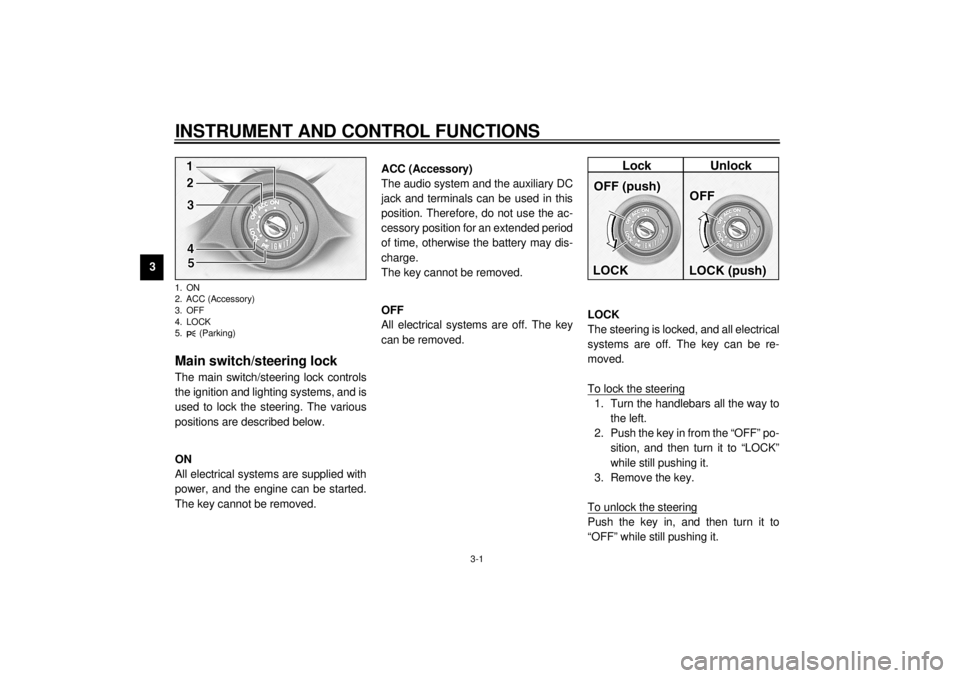
Main switch/steering lock The main switch/steering lock controls
the ignition and lighting systems, and is
used to lock the steering. The various
positions are described below.
EAU00036
ON
All electrical systems are supplied with
power, and the engine can be started.
The key cannot be removed.
EAU01842
ACC (Accessory)
The audio system and the auxiliary DC
jack and terminals can be used in this
position. Therefore, do not use the ac-
cessory position for an extended period
of time, otherwise the battery may dis-
charge.
The key cannot be removed.
EAU00038
OFF
All electrical systems are off. The key
can be removed.
EAU00040
LOCK
The steering is locked, and all electrical
systems are off. The key can be re-
moved.
To lock the steering1. Turn the handlebars all the way to
the left.
2. Push the key in from the “OFF” po-
sition, and then turn it to “LOCK”
while still pushing it.
3. Remove the key.
To unlock the steeringPush the key in, and then turn it to
“OFF” while still pushing it.
1. ON
2. ACC (Accessory)
3. OFF
4. LOCK
5. (Parking)E_5jc.book Page 1 Monday, January 22, 2001 12:12 PM
Page 18 of 132

INSTRUMENT AND CONTROL FUNCTIONS
3-3
3
EAU03034
Indicator and warning lights
EAU03299
1. Turn signal indicator lights
“” / “ ”
The corresponding indicator light flash-
es when the turn signal switch is
pushed to the left or right.
EAU00063
2. High beam indicator light “ ”
This indicator light comes on when the
high beam of the headlight is switched
on.
EAU03201
3. Oil level warning light “ ”
This warning light comes on when the
engine oil level is low.
The electrical circuit of the warning light
can be checked according to the fol-
lowing procedure.
1. Set the engine stop switch to “ ”
and turn the key to “ON”.
2. Shift the transmission into the neu-
tral position or pull the clutch lever.
3. Push the start switch. If the warn-
ing light does not come on while
pushing the start switch, have a
Yamaha dealer check the electri-
cal circuit.
NOTE:@ Even if the oil level is sufficient, the
warning light may flicker when riding on
a slope or during sudden acceleration
or deceleration, but this is not a mal-
function. @
EAU01774
4. Overdrive indicator light “O/D”
This indicator light comes on when the
transmission is in overdrive (5th gear).
EAU00091
5. Engine trouble warning light
“”
This warning light comes on or flashes
when an electrical circuit monitoring
the engine is defective. When this oc-
curs, have the Yamaha dealer check
the self-diagnosis system.
E_5jc.book Page 3 Monday, January 22, 2001 12:12 PM
Page 19 of 132

INSTRUMENT AND CONTROL FUNCTIONS
3-4
3
EAU00079
6. Fuel level warning light “ ”
This warning light comes on when the
fuel level drops below approximately
3.5 L. When this occurs, turn the fuel
cock lever to the “RES” position and re-
fuel as soon as possible.
EAU01773
7. Cruise control indicator lights
See page 3-6 for an explanation of
these indicator lights.
EAU00061
8. Neutral indicator light “ ”
This indicator light comes on when the
transmission is in the neutral position.
EAU01707
9. Coolant temperature warning
light “ ”
This warning light comes on when the
engine overheats. When this occurs,
stop the engine immediately and allow
the engine to cool.
The electrical circuit of the warning light
can be checked according to the fol-
lowing procedure.
1. Set the engine stop switch to “ ”
and turn the key to “ON”.
2. Shift the transmission into the neu-
tral position or pull the clutch lever.
3. Push the start switch. If the warn-
ing light does not come on while
pushing the start switch, have a
Yamaha dealer check the electri-
cal circuit.
EC000002
CAUTION:@ Do not operate the engine if it is
overheated. @
E_5jc.book Page 4 Monday, January 22, 2001 12:12 PM
Page 24 of 132

INSTRUMENT AND CONTROL FUNCTIONS
3-9
3
EAU00118
Handlebar switches
EAU00119
1. Pass switch “ ”
Press this switch to flash the headlight.
EAU03888
2. Dimmer switch “ / ”
Set this switch to “ ” for the high
beam and to “ ” for the low beam.
EAU03889
3. Turn signal switch “ / ”
To signal a right-hand turn, push this
switch to “ ”. To signal a left-hand
turn, push this switch to “ ”. When
released, the switch returns to the cen-
ter position. To cancel the turn signal
lights, push the switch in after it has re-
turned to the center position.
EAU00129
4. Horn switch “ ”
Press this switch to sound the horn.
EAU03890
5. Engine stop switch “ / ”
Set this switch to “ ” before starting
the engine. Set this switch to “ ” to
stop the engine in case of an emergen-
cy, such as when the motorcycle over-
turns or when the throttle cable is
stuck.
EAU03966
6. Light switch “ / / ”
Set this switch to “ ” to turn on the
auxiliary light, meter lighting, taillight
and license plate light. Set the switch to
“ ” to turn on the headlight also. Set
the switch to “ ” to turn off all the
lights.
E_5jc.book Page 9 Monday, January 22, 2001 12:12 PM
Page 25 of 132

INSTRUMENT AND CONTROL FUNCTIONS
3-10
3
EAU01859
7. Cruise control switches
See page 3-6 for an explanation of the
cruise control system.
EAU00143
8. Start switch “ ”
Push this switch to crank the engine
with the starter.
EC000005
CAUTION:@ See page 6-1 for starting instruc-
tions prior to starting the engine. @
EAU00152
Clutch lever The clutch lever is located at the left
handlebar grip. To disengage the
clutch, pull the lever toward the handle-
bar grip. To engage the clutch, release
the lever. The lever should be pulled
rapidly and released slowly for smooth
clutch operation.
The clutch lever is equipped with a
clutch switch, which is part of the ignition
circuit cut-off system. (See page 3-22
for an explanation of the ignition circuit
cut-off system.)
EAU01215
Shift pedal The shift pedal is located on the left
side of the engine and is used in com-
bination with the clutch lever when
shifting the gears of the 5-speed con-
stant-mesh transmission equipped on
this motorcycle.NOTE:@ Use your toes or heel to shift up and
your toes to shift down. @
1. Clutch lever
1. Shift pedal
E_5jc.book Page 10 Monday, January 22, 2001 12:12 PM
Page 27 of 132

INSTRUMENT AND CONTROL FUNCTIONS
3-12
3 2. Turn the key counterclockwise to
the original position, remove it,
and then close the lock cover.
NOTE:@ The fuel tank cap cannot be installed
unless the key is in the lock. In addition,
the key cannot be removed if the cap is
not properly installed and locked. @
EW000024
WARNING
@ Make sure that the fuel tank cap is
properly installed before riding. @
EAU03753
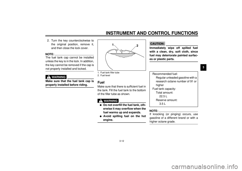
Fuel Make sure that there is sufficient fuel in
the tank. Fill the fuel tank to the bottom
of the filler tube as shown.
EW000130
WARNING
_ l
Do not overfill the fuel tank, oth-
erwise it may overflow when the
fuel warms up and expands.
l
Avoid spilling fuel on the hot
engine.
_
EAU00185
CAUTION:_ Immediately wipe off spilled fuel
with a clean, dry, soft cloth, since
fuel may deteriorate painted surfac-
es or plastic parts. _
EAU00191
NOTE:_ If knocking (or pinging) occurs, use
gasoline of a different brand or with a
higher octane grade. _
1. Fuel tank filler tube
2. Fuel level
Recommended fuel:
Regular unleaded gasoline with a
research octane number of 91 or
higher
Fuel tank capacity:
Total amount:
22.5 L
Reserve amount:
3.5 L
E_5jc.book Page 12 Monday, January 22, 2001 12:12 PM
Page 28 of 132
INSTRUMENT AND CONTROL FUNCTIONS
3-13
3
EAU02955
Fuel tank breather hose Before operating the motorcycle:l
Check the fuel tank breather hose
connection.
l
Check the fuel tank breather hose
for cracks or damage, and replace
it if damaged.
l
Make sure that the end of the fuel
tank breather hose is not blocked,
and clean it if necessary.
EAU02969
Fuel cock The fuel cock supplies fuel from the
tank to the carburetors while also filter-
ing it.
The fuel cock lever positions are ex-
plained as follows and shown in the il-
lustrations.
OFF
With the fuel cock lever in this position,
fuel will not flow. Always turn the fuel
cock lever to this position when the en-
gine is not running.ON
With the fuel cock lever in this position,
fuel flows to the carburetors. Turn the
fuel cock lever to this position when
starting the engine and riding.
1. Fuel tank breather hose
OFF: closed position
ON: normal position
E_5jc.book Page 13 Monday, January 22, 2001 12:12 PM