Page 25 of 132

INSTRUMENT AND CONTROL FUNCTIONS
3-10
3
EAU01859
7. Cruise control switches
See page 3-6 for an explanation of the
cruise control system.
EAU00143
8. Start switch “ ”
Push this switch to crank the engine
with the starter.
EC000005
CAUTION:@ See page 6-1 for starting instruc-
tions prior to starting the engine. @
EAU00152
Clutch lever The clutch lever is located at the left
handlebar grip. To disengage the
clutch, pull the lever toward the handle-
bar grip. To engage the clutch, release
the lever. The lever should be pulled
rapidly and released slowly for smooth
clutch operation.
The clutch lever is equipped with a
clutch switch, which is part of the ignition
circuit cut-off system. (See page 3-22
for an explanation of the ignition circuit
cut-off system.)
EAU01215
Shift pedal The shift pedal is located on the left
side of the engine and is used in com-
bination with the clutch lever when
shifting the gears of the 5-speed con-
stant-mesh transmission equipped on
this motorcycle.NOTE:@ Use your toes or heel to shift up and
your toes to shift down. @
1. Clutch lever
1. Shift pedal
E_5jc.book Page 10 Monday, January 22, 2001 12:12 PM
Page 26 of 132
INSTRUMENT AND CONTROL FUNCTIONS
3-11
3
EAU00158
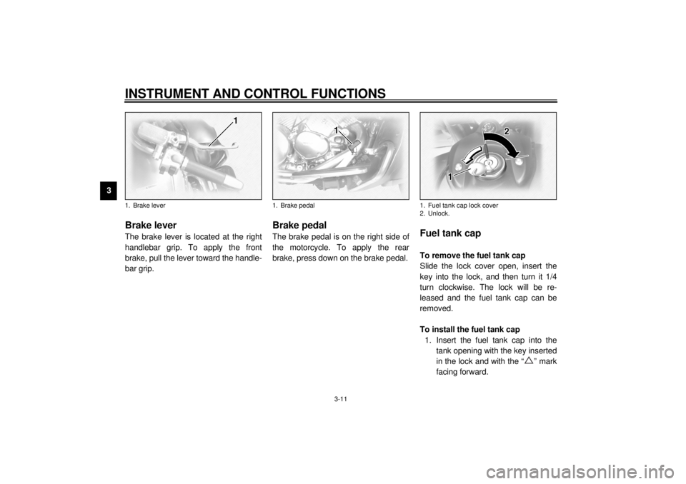
Brake lever The brake lever is located at the right
handlebar grip. To apply the front
brake, pull the lever toward the handle-
bar grip.
EAU00162
Brake pedal The brake pedal is on the right side of
the motorcycle. To apply the rear
brake, press down on the brake pedal.
EAU02917
Fuel tank cap To remove the fuel tank cap
Slide the lock cover open, insert the
key into the lock, and then turn it 1/4
turn clockwise. The lock will be re-
leased and the fuel tank cap can be
removed.
To install the fuel tank cap
1. Insert the fuel tank cap into the
tank opening with the key inserted
in the lock and with the “ ” mark
facing forward.
1. Brake lever
1. Brake pedal
1. Fuel tank cap lock cover
2. Unlock.
E_5jc.book Page 11 Monday, January 22, 2001 12:12 PM
Page 27 of 132

INSTRUMENT AND CONTROL FUNCTIONS
3-12
3 2. Turn the key counterclockwise to
the original position, remove it,
and then close the lock cover.
NOTE:@ The fuel tank cap cannot be installed
unless the key is in the lock. In addition,
the key cannot be removed if the cap is
not properly installed and locked. @
EW000024
WARNING
@ Make sure that the fuel tank cap is
properly installed before riding. @
EAU03753
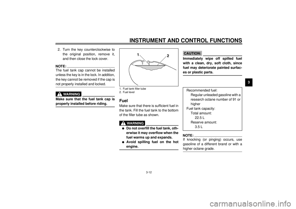
Fuel Make sure that there is sufficient fuel in
the tank. Fill the fuel tank to the bottom
of the filler tube as shown.
EW000130
WARNING
_ l
Do not overfill the fuel tank, oth-
erwise it may overflow when the
fuel warms up and expands.
l
Avoid spilling fuel on the hot
engine.
_
EAU00185
CAUTION:_ Immediately wipe off spilled fuel
with a clean, dry, soft cloth, since
fuel may deteriorate painted surfac-
es or plastic parts. _
EAU00191
NOTE:_ If knocking (or pinging) occurs, use
gasoline of a different brand or with a
higher octane grade. _
1. Fuel tank filler tube
2. Fuel level
Recommended fuel:
Regular unleaded gasoline with a
research octane number of 91 or
higher
Fuel tank capacity:
Total amount:
22.5 L
Reserve amount:
3.5 L
E_5jc.book Page 12 Monday, January 22, 2001 12:12 PM
Page 28 of 132
INSTRUMENT AND CONTROL FUNCTIONS
3-13
3
EAU02955
Fuel tank breather hose Before operating the motorcycle:l
Check the fuel tank breather hose
connection.
l
Check the fuel tank breather hose
for cracks or damage, and replace
it if damaged.
l
Make sure that the end of the fuel
tank breather hose is not blocked,
and clean it if necessary.
EAU02969
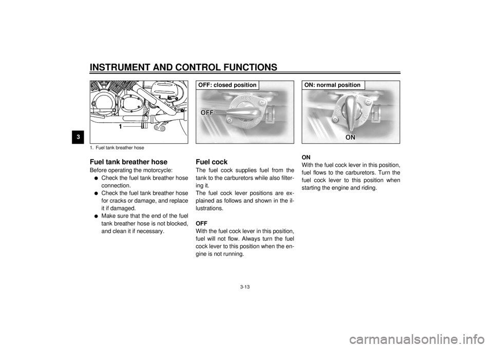
Fuel cock The fuel cock supplies fuel from the
tank to the carburetors while also filter-
ing it.
The fuel cock lever positions are ex-
plained as follows and shown in the il-
lustrations.
OFF
With the fuel cock lever in this position,
fuel will not flow. Always turn the fuel
cock lever to this position when the en-
gine is not running.ON
With the fuel cock lever in this position,
fuel flows to the carburetors. Turn the
fuel cock lever to this position when
starting the engine and riding.
1. Fuel tank breather hose
OFF: closed position
ON: normal position
E_5jc.book Page 13 Monday, January 22, 2001 12:12 PM
Page 29 of 132

INSTRUMENT AND CONTROL FUNCTIONS
3-14
3
RES
This indicates reserve. With the fuel
cock lever in this position, the fuel re-
serve is made available. Turn the fuel
cock lever to this position if you run out
of fuel while riding. When this occurs,
refuel as soon as possible and be sure
to turn the fuel cock lever back to “ON”!
EAU04038
Starter (choke) knob “ ” Starting a cold engine requires a richer
air-fuel mixture, which is supplied by
the starter (choke).
Move the knob in direction
a to turn on
the starter (choke).
Move the knob in direction
b to turn off
the starter (choke).
EAU03372
Locking the steering with a
padlock In addition to the main switch/steering
lock, there are brackets on the right
side of the steering head pipe for lock-
ing the steering with a padlock. To do
so, turn the handlebar until the holes in
the two brackets are aligned, and then
lock the steering with a suitable pad-
lock.
RES: reserve position
1. Starter (choke) knob “ ”
E_5jc.book Page 14 Monday, January 22, 2001 12:12 PM
Page 30 of 132
INSTRUMENT AND CONTROL FUNCTIONS
3-15
3
EAU01781
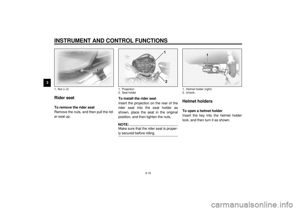
Rider seat To remove the rider seat
Remove the nuts, and then pull the rid-
er seat up.To install the rider seat
Insert the projection on the rear of the
rider seat into the seat holder as
shown, place the seat in the original
position, and then tighten the nuts.
NOTE:@ Make sure that the rider seat is proper-
ly secured before riding. @
EAU01782
Helmet holders To open a helmet holder
Insert the key into the helmet holder
lock, and then turn it as shown.
1. Nut (´ 2)
1. Projection
2. Seat holder
1. Helmet holder (right)
2. Unlock.
E_5jc.book Page 15 Monday, January 22, 2001 12:12 PM
Page 31 of 132

INSTRUMENT AND CONTROL FUNCTIONS
3-16
3
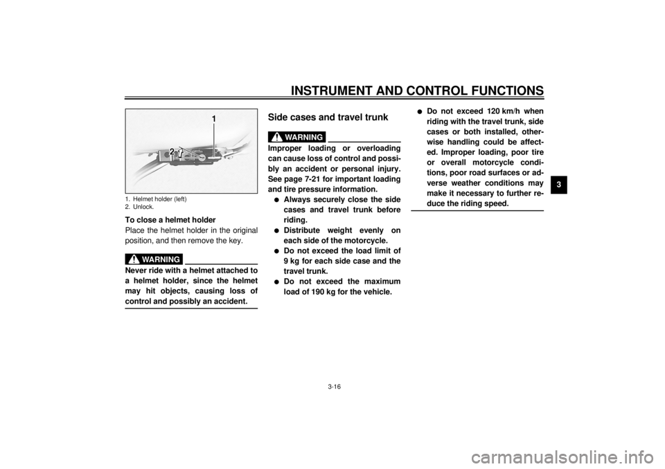
To close a helmet holder
Place the helmet holder in the original
position, and then remove the key.
EWA00015
WARNING
@ Never ride with a helmet attached to
a helmet holder, since the helmet
may hit objects, causing loss of
control and possibly an accident. @
EAU01866*
Side cases and travel trunk
EWA00021*
WARNING
@ Improper loading or overloading
can cause loss of control and possi-
bly an accident or personal injury.
See page 7-21 for important loading
and tire pressure information.l
Always securely close the side
cases and travel trunk before
riding.
l
Distribute weight evenly on
each side of the motorcycle.
l
Do not exceed the load limit of
9 kg for each side case and the
travel trunk.
l
Do not exceed the maximum
load of 190 kg for the vehicle.
l
Do not exceed 120 km/h when
riding with the travel trunk, side
cases or both installed, other-
wise handling could be affect-
ed. Improper loading, poor tire
or overall motorcycle condi-
tions, poor road surfaces or ad-
verse weather conditions may
make it necessary to further re-
duce the riding speed.
@
1. Helmet holder (left)
2. Unlock.
E_5jc.book Page 16 Monday, January 22, 2001 12:12 PM
Page 32 of 132
INSTRUMENT AND CONTROL FUNCTIONS
3-17
3
Side cases
To open a side case
1. Insert the key into the lock, turn it
counterclockwise, and then push it
in.2. Fold the side case lid up.
To close a side case
1. Fold the side case lid down.
2. Turn the key clockwise, and then
remove it.NOTE:Push both sides of the lid down so that
both latches snap into place. @
Travel trunk
To open the travel trunk1. Insert the key into the lock, turn it
counterclockwise, and then push it
in.
1. Side case lock
2. Unlock.
1. Main storage area
2. Storage pouch
1. Travel trunk lock
2. Unlock.
E_5jc.book Page 17 Monday, January 22, 2001 12:12 PM