2001 YAMAHA XVZ1300TF warning light
[x] Cancel search: warning lightPage 15 of 132

3
INSTRUMENT AND CONTROL FUNCTIONS
Main switch/steering lock ..................................... 3-1
Indicator and warning lights ................................ 3-3
Speedometer unit ................................................ 3-5
Cruise control system ........................................... 3-6
Fuel gauge ........................................................... 3-8
Anti-theft alarm (optional) .................................... 3-8
Handlebar switches ............................................. 3-9
Clutch lever ........................................................ 3-10
Shift pedal .......................................................... 3-10
Brake lever ......................................................... 3-11
Brake pedal ........................................................ 3-11
Fuel tank cap ..................................................... 3-11
Fuel .................................................................... 3-12Fuel tank breather hose .................................... 3-13
Fuel cock ........................................................... 3-13
Starter (choke) knob ......................................... 3-14
Locking the steering with a padlock .................. 3-14
Rider seat .......................................................... 3-15
Helmet holders .................................................. 3-15
Side cases and travel trunk ............................... 3-16
Adjusting the front fork ...................................... 3-19
Adjusting the shock absorber assembly ............ 3-20
Sidestand .......................................................... 3-21
Ignition circuit cut-off system ............................. 3-22
Auxiliary DC jack and terminals ........................ 3-24
E_5jc.book Page 1 Monday, January 22, 2001 12:12 PM
Page 17 of 132

INSTRUMENT AND CONTROL FUNCTIONS
3-2
3
EW000016
WARNING
@ Never turn the key to “OFF” or
“LOCK” while the motorcycle is
moving, otherwise the electrical
systems will be switched off, which
may result in loss of control or an
accident. Make sure that the motor-
cycle is stopped before turning the
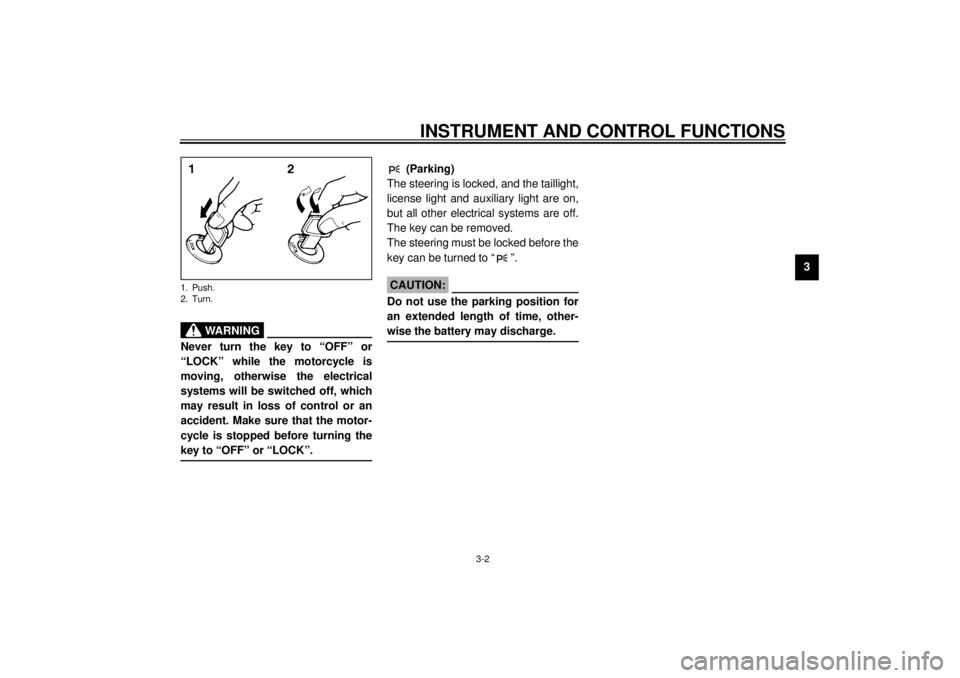
key to “OFF” or “LOCK”. @1. Push.
2. Turn.
EAU01861
(Parking)
The steering is locked, and the taillight,
license light and auxiliary light are on,
but all other electrical systems are off.
The key can be removed.
The steering must be locked before the
key can be turned to “ ”.
ECA00043
CAUTION:_ Do not use the parking position for
an extended length of time, other-
wise the battery may discharge. _
E_5jc.book Page 2 Monday, January 22, 2001 12:12 PM
Page 18 of 132

INSTRUMENT AND CONTROL FUNCTIONS
3-3
3
EAU03034
Indicator and warning lights
EAU03299
1. Turn signal indicator lights
“” / “ ”
The corresponding indicator light flash-
es when the turn signal switch is
pushed to the left or right.
EAU00063
2. High beam indicator light “ ”
This indicator light comes on when the
high beam of the headlight is switched
on.
EAU03201
3. Oil level warning light “ ”
This warning light comes on when the
engine oil level is low.
The electrical circuit of the warning light
can be checked according to the fol-
lowing procedure.
1. Set the engine stop switch to “ ”
and turn the key to “ON”.
2. Shift the transmission into the neu-
tral position or pull the clutch lever.
3. Push the start switch. If the warn-
ing light does not come on while
pushing the start switch, have a
Yamaha dealer check the electri-
cal circuit.
NOTE:@ Even if the oil level is sufficient, the
warning light may flicker when riding on
a slope or during sudden acceleration
or deceleration, but this is not a mal-
function. @
EAU01774
4. Overdrive indicator light “O/D”
This indicator light comes on when the
transmission is in overdrive (5th gear).
EAU00091
5. Engine trouble warning light
“”
This warning light comes on or flashes
when an electrical circuit monitoring
the engine is defective. When this oc-
curs, have the Yamaha dealer check
the self-diagnosis system.
E_5jc.book Page 3 Monday, January 22, 2001 12:12 PM
Page 19 of 132

INSTRUMENT AND CONTROL FUNCTIONS
3-4
3
EAU00079
6. Fuel level warning light “ ”
This warning light comes on when the
fuel level drops below approximately
3.5 L. When this occurs, turn the fuel
cock lever to the “RES” position and re-
fuel as soon as possible.
EAU01773
7. Cruise control indicator lights
See page 3-6 for an explanation of
these indicator lights.
EAU00061
8. Neutral indicator light “ ”
This indicator light comes on when the
transmission is in the neutral position.
EAU01707
9. Coolant temperature warning
light “ ”
This warning light comes on when the
engine overheats. When this occurs,
stop the engine immediately and allow
the engine to cool.
The electrical circuit of the warning light
can be checked according to the fol-
lowing procedure.
1. Set the engine stop switch to “ ”
and turn the key to “ON”.
2. Shift the transmission into the neu-
tral position or pull the clutch lever.
3. Push the start switch. If the warn-
ing light does not come on while
pushing the start switch, have a
Yamaha dealer check the electri-
cal circuit.
EC000002
CAUTION:@ Do not operate the engine if it is
overheated. @
E_5jc.book Page 4 Monday, January 22, 2001 12:12 PM
Page 20 of 132

INSTRUMENT AND CONTROL FUNCTIONS
3-5
3
EAU03565
Speedometer unit The speedometer unit is equipped with
the following:l
a digital speedometer (which
shows riding speed)
l
an odometer (which shows the to-
tal distance traveled)
l
two tripmeters (which show the
distance traveled since they were
last set to zero)
l
a fuel reserve tripmeter (which
shows the distance traveled on the
fuel reserve)
l
a clockOdometer and tripmeter modes
Pushing the “SELECT” button switches
the display between the odometer
mode “ODO” and the tripmeter modes
“TRIP 1” and “TRIP 2” in the following
order:
ODO
® TRIP 1
® TRIP 2
® ODO
If the fuel level warning light comes on
(see page 3-4), the odometer display
will automatically change to the fuel re-
serve tripmeter mode “TRIP F” and
start counting the distance traveled
from that point. In that case, pushing
the “SELECT” button switches the dis-
play between the various tripmeter and
odometer modes in the following order:
TRIP F
® TRIP 1
® TRIP 2
® ODO
®
TRIP FTo reset a tripmeter, select it by push-
ing the “SELECT” button, and then
push the “RESET” button. If you do not
reset the fuel reserve tripmeter manu-
ally, it will reset itself automatically and
the display will return to “TRIP 1” after
refueling and traveling 5 km.
NOTE:@ After resetting the fuel reserve tripme-
ter, the display will return to “TRIP 1”,
unless a different mode had been pre-
viously selected; in that case, the dis-
play automatically returns to the prior
mode. @Clock mode
To change the display to the clock
mode, push both the “SELECT” and
“RESET” buttons.
To change the display back to the
odometer modes, push the “SELECT”
button.
1. Speedometer
2. Odometer/tripmeters/clock
3. “RESET” button
4. “SELECT” buttonE_5jc.book Page 5 Monday, January 22, 2001 12:12 PM
Page 23 of 132

INSTRUMENT AND CONTROL FUNCTIONS
3-8
3 Push the “RES/ACC” side of the cruise
control switch to reactivate the system.
The traveling speed will return to the
previously set speed. The “RES” indi-
cator light will flash during this time and
then go off. Once the cruise control
system is reactivated, the “SET” indica-
tor light will come on.
Push the “CRUISE” switch to the right
to turn the cruise control system off
completely.
EWA00019
WARNING
_ If the cruise control system is defec-
tive, the “SET” and “RES” indicator
lights will flash simultaneously. If
this occurs, turn the cruise control
system off and have a Yamaha deal-
er check it. _
EAU01779
Fuel gauge The fuel gauge indicates the amount of
fuel in the fuel tank. The display seg-
ments of the fuel gauge disappear to-
wards “E” (Empty) as the fuel level
decreases. When only one segment is
left near “E”, refuel as soon as possi-
ble.NOTE:@ This fuel gauge is equipped with a self-
diagnosis system. If the electrical cir-
cuit is defective, first the display seg-
ments and then either “E” or “F” will
flash. If this occurs, have a Yamaha
dealer check the electrical circuit. @
EAU00109
Anti-theft alarm (optional) This motorcycle can be equipped with
an optional anti-theft alarm by a
Yamaha dealer. Contact a Yamaha
dealer for more information.
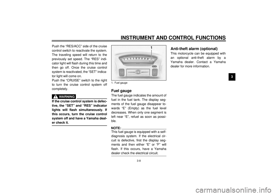
1. Fuel gauge
E_5jc.book Page 8 Monday, January 22, 2001 12:12 PM
Page 50 of 132

AUDIO SYSTEM
4-9
4
Cassette deck operation
WARNING
_ l
It is dangerous to operate the
cassette deck while riding. Nev-
er take your hands off the han-
dlebars while riding.
l
Keep the volume at a low
enough level to be aware of traf-
fic conditions and ensure
safety.
_
CAUTION:_ l
Keep the cassette deck lid
closed at all times, except when
inserting or removing a cas-
sette.
l
Do not leave cassette tapes in
direct sunlight for a long period
of time.
l
Do not allow the inside of the
cassette deck to get wet. If this
happens, keep the cassette
deck lid open and dry out the
deck in the shade.
l
To clean the tape head, use a
de-magnetizing cleaning cas-
sette, but be sure to turn the
volume all the way down to
avoid speaker damage.
_
1. Cassette deck compartment
2. Eject (“ ”) button
3. Cassette deck lidE_5jc.book Page 9 Monday, January 22, 2001 12:12 PM
Page 67 of 132

OPERATION AND IMPORTANT RIDING POINTS
6-2
6 1. Turn the fuel cock lever to “ON”.
2. Turn the key to “ON” and make
sure that the engine stop switch is
set to “ ”.
EC000035
CAUTION:_ If the fuel level warning light comes
on, check the fuel level, and, if nec-
essary, refuel as soon as possible. _3. Shift the transmission into the neu-
tral position.
NOTE:_ When the transmission is in the neutral
position, the neutral indicator light
should be on, otherwise have a
Yamaha dealer check the electrical cir-
cuit. _
4. Turn the starter (choke) on and
completely close the throttle. (See
page 3-14 for starter (choke) oper-
ation.)
5. Start the engine by pushing the
start switch.NOTE:_ If the engine fails to start, release the
start switch, wait a few seconds, and
then try again. Each starting attempt
should be as short as possible to pre-
serve the battery. Do not crank the en-
gine more than 10 seconds on any one
attempt. _
E_5jc.book Page 2 Monday, January 22, 2001 12:12 PM