Page 2916 of 4323

INSTALLATION
1. INSTALL GENERATOR
(a) Install the generator with the bolt and the 2 nuts.
Torque:
Bolt: 39 N")
CH0M3±02
B00809
CH±16
± CHARGINGGENERATOR
2908 Author�: Date�:
2005 SEQUOIA (RM1146U)
INSTALLATION
1. INSTALL GENERATOR
(a) Install the generator with the bolt and the 2 nuts.
Torque:
Bolt: 39 N´m (400 kgf´cm, 29 ft´lbf)
Nut 10 mm: 39 N´m (400 kgf´cm, 29 ft´lbf)
Nut 8 mm: 15.5 N´m (158 kgf´cm, 11 ft´lbf)
(b) Connect the generator connector.
(c) Connect the generator wire with the nut.
Torque: 9.8 N´m (100 kgf´cm, 87 in.´lbf)
(d) Install the terminal cap.
(e) Install the wire clamp to the cord clip on the generator.
2. INSTALL PS VANE PUMP (See page SR±36)
3. INSTALL DRIVE BELT
Install the belt by turning the belt tensioner counterclockwise.
HINT:
The pulley bolt for the belt tensioner has a left ± hand thread.
4. CONNECT INTAKE AIR CONNECTOR TO THROTTLE
BODY
5. PERFORM ON±VEHICLE INSPECTION
(See page CH±1)
6. INSTALL THROTTLE BODY COVER
7. INSTALL ENGINE UNDER COVER
8. CONNECT CABLE TO NEGATIVE (±) BATTERY TER-
MINAL
9. PERFORM INITIALIZATION (See page IN±20)
Some system need initialzation when disconnecting the cable
from the battery terminal.
Page 2917 of 4323
AT130±01
± AUTOMATIC TRANSMISSION (A750E, A750F)AUTOMATIC TRANSMISSION SYSTEM
AT±1
2909 Author�: Date�:
2005 SEQUOIA (RM1146U)
AUTOMATIC TRANSMISSION SYSTEM
PRECAUTION
NOTICE:
When disconnecting the battery terminal, initialize the following system after the terminal is recon-
nected.
System NameSee Page
Back Door Power Window Control SystemBE±77
Page 2947 of 4323
TR04G±02
± TRANSFERTRANSFER SYSTEM
TR±1
2939 Author�: Date�:
2005 SEQUOIA (RM1146U)
TRANSFER SYSTEM
PRECAUTION
NOTICE:
When disconnecting the battery terminal, initialize the following system after the terminal is recon-
nected.
System NameSee Page
Back Door Power Window Control SystemBE±77
When working with FIPG material, you must observe the following:
�Using a razor blade and gasket scraper, remove all the old FIPG material from gasket surfaces.
�Thoroughly clean all components to remove any loose material.
�Clean both sealing surfaces with a non±residue solvent.
�Apply FIPG in an approx. 1.2 mm (0.047 in.) wide bead along the sealing surface.
�Parts must be assembled within 10 minutes of FIPG application. Otherwise, the FIPG material
must be removed and reapplied.
Page 2988 of 4323

8. INSPECT 4LO (4WD and differential lock ºLOCKº) \"
2W")
F19324
2WD/4HI Switch
F19325
A GND
4LO
CPU 4WD
B TR±42
± TRANSFERONE TOUCH 2±4 SELECTOR SYSTEM
2980 Author�: Date�:
2005 SEQUOIA (RM1146U)
8. INSPECT 4LO (4WD and differential lock ºLOCKº) "
2WD
(a) Start the engine.
(b) Push the 4LO switch once.
(c) Check that the 4LO indicator light stays lit after blinking.
(d) Push the differential lock switch once.
(e) Check that the center differential lock indicator light stays
lit after blinking.
(f) Push the 2WD/4HI switch once.
(g) Check that the 4LO and center differential lock indicator
lights go off after the 4LO and 4WD indicators are blink-
ing.
9. INSPECT 2WD/4HI, 4LO AND DIFFERENTIAL LOCK
SWITCH CONTINUITY
(a) Remove the instrument panel finish lower panel.
(b) Inspect the continuity between each terminal.
Switch positionTester connectionSpecified condition
Diff. Lock OFFB±8 ± A±10No continuity
Diff. Lock Hold ONB±8 ± A±10Continuity
4LO OFFB±9 ± A±10No continuity
4LO Hold ONB±9 ± A±10Continuity
2WD/4HI OFFB±10 ± A±10No continuity
2WD/4HI Hold ONB±10 ± A±10Continuity
If continuity is not as specified, replace the instrument panel fin-
ish lower panel.
Page 2990 of 4323

12. INSPECT FOUR WHEEL DRIVE CONTROL ECU
(a) Connect the wire harness side connector to the four")
F19566
TR±44
± TRANSFERONE TOUCH 2±4 SELECTOR SYSTEM
2982 Author�: Date�:
2005 SEQUOIA (RM1146U)
12. INSPECT FOUR WHEEL DRIVE CONTROL ECU
(a) Connect the wire harness side connector to the four wheel drive control ECU and inspect the wire har-
ness side connector from the back, as shown.
STANDARD VALUE OF ECU TERMINAL
Terminals (Symbols)ConditionSTD Voltage (V)
3 (HM1) ± 4 (HM2)
�Ignition switch ON
�Four wheel drive control switch ºH4º position " Four wheel drive control switch
ºL4º position
10 to 14 " 2 or less
or
4 (HM2) ± 3 (HM1)
�Ignition switch ON
�Four wheel drive control switch ºL4º position " Four wheel drive control switch
ºH4º position
or
0 (0.5 s) to 14 (50 ms)
pulse generation
2 (TM1) ± 1 (TM2)
�Ignition switch ON
�Differential lock switch is in ºOFFº position
�Four wheel drive control switch ºH2º position " Four wheel drive control switch
ºH4º position
10 to 14 " 2 or less
or
1 (TM2) ± 2 (TM1)
�Ignition switch ON
�Keep pressing the differential lock switch for approx. 2 seconds to turn it ON
�Four wheel drive control switch ºH4ºor ºL4º position " Four wheel drive control
switch ºH2º position
or
0 (0.5 s) to 14 (50 ms)
pulse generation
5 (DM1) ± 6 (DM2)�Ignition switch ON
�A.D.D. FREE "A.D.D. LOCK10 to 14 " 2 or less
or
6 (DM2) ± 5 (DM2)�Ignition switch ON
�A.D.D. LOCK "A.D.D. FREE
or
0 (0.5 s) to 14 (50 ms)
pulse generation
4 (HM2) ± 7 (GND)
�Ignition switch ON
�Four wheel drive control switch ºH4º position " Four wheel drive control switch
ºL4º position
2 or less " 10 to 14
7 (GND) ± Body ground�Ignition switch OFFContinuity
12 (IG) ± 7 (GND)�Ignition switch ON10 to 14
18 (DL2) ± 7 (GND)�Ignition switch ON
�A.D.D. LOCK "A.D.D. FREE0.88 or less " 10 to 14
19 (DL1) ± 7 (GND)�Ignition switch ON
�A.D.D. FREE "A.D.D. LOCK0.88 or less " 10 to 14
23 (HL1) ± 7 (GND)
�Ignition switch ON
�Four wheel drive control switch ºH4º position " Four wheel drive control switch
ºL4º position
10 to 14 " 1.5 or less
25 (2±4) ± 7 (GND)
�Ignition switch ON
�Four wheel drive control switch ºL4º position " Four wheel drive control switch
ºH2º or ºH4º position
10 to 14 " 1.5 or less
26 (SPD) ± 7 (GND)�During drivingPulse generation
Page 3017 of 4323
SA2CQ±01
F16821
F16821
± SUSPENSION AND AXLETIRE PRESSURE MONITOR RECEIVER
SA±13
3009 Author�: Date�:
2005 SEQUOIA (RM1146U)
REPLACEMENT
1. DISCONNECT CABLE FROM NEGATIVE BATTERY
TERMINAL
2. REMOVE REAR TRIM (See page BO±101)
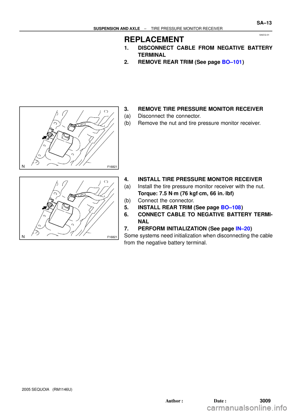
3. REMOVE TIRE PRESSURE MONITOR RECEIVER
(a) Disconnect the connector.
(b) Remove the nut and tire pressure monitor receiver.
4. INSTALL TIRE PRESSURE MONITOR RECEIVER
(a) Install the tire pressure monitor receiver with the nut.
Torque: 7.5 NVm (76 kgfVcm, 66 in.Vlbf)
(b) Connect the connector.
5. INSTALL REAR TRIM (See page BO±108)
6. CONNECT CABLE TO NEGATIVE BATTERY TERMI-
NAL
7. PERFORM INITIALIZATION (See page IN±20)
Some systems need initialization when disconnecting the cable
from the negative battery terminal.
Page 3019 of 4323
SA2CS±01
F19828
F19829
Lithium battery
Terminal
± SUSPENSION AND AXLETIRE PRESSURE MONITOR VALVE
SA±15
3011 Author�: Date�:
2005 SEQUOIA (RM1146U)
DISPOSAL
HINT:
The tire pressure monitor valve sub±assy is powered by a lithi-
um battery. When disposing of the tire pressure monitor valve
sub±assy, remove the battery and dispose of it correctly.
DISPOSE OF TIRE PRESSURE MONITOR VALVE
(a) Insert the tip of a screwdriver into the clearance and pry
off the cover. Remove the back cover.
(b) The battery and base board covered with silicone resin
are exposed. While taking out the battery, cut off the 2 ter-
minals which connect the battery and base board.
Page 3024 of 4323
SA2CV±01
F16822
F16822
SA±20
± SUSPENSION AND AXLETIRE PRESSURE MONITOR ECU
3016 Author�: Date�:
2005 SEQUOIA (RM1146U)
REPLACEMENT
1. DISCONNECT CABLE FROM NEGATIVE BATTERY
TERMINAL
2. REMOVE INTEGRATION CONTROL PANEL
(See page BO±89)
3. REMOVE GLOVE COMPARTMENT
(See page BO±89)
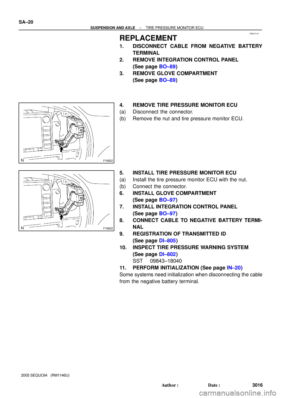
4. REMOVE TIRE PRESSURE MONITOR ECU
(a) Disconnect the connector.
(b) Remove the nut and tire pressure monitor ECU.
5. INSTALL TIRE PRESSURE MONITOR ECU
(a) Install the tire pressure monitor ECU with the nut.
(b) Connect the connector.
6. INSTALL GLOVE COMPARTMENT
(See page BO±97)
7. INSTALL INTEGRATION CONTROL PANEL
(See page BO±97)
8. CONNECT CABLE TO NEGATIVE BATTERY TERMI-
NAL
9. REGISTRATION OF TRANSMITTED ID
(See page DI±805)
10. INSPECT TIRE PRESSURE WARNING SYSTEM
(See page DI±802)
SST 09843±18040
11. PERFORM INITIALIZATION (See page IN±20)
Some systems need initialization when disconnecting the cable
from the negative battery terminal.