Page 1751 of 4323
DI26U±39
± DIAGNOSTICSCRUISE CONTROL SYSTEM
DI±1549
1743 Author�: Date�:
2005 SEQUOIA (RM1146U)
DIAGNOSTIC TROUBLE CODE CHART
If a trouble code is displayed during the DTC check, check the circuit listed for that code. For details of each
code, refer to the ºSee pageº under the respective ºDTC No.º in the DTC chart.
DTC No.
(See Page)Detection ItemTrouble Area
P0500/21
(DI±1551)Vehicle Speed Sensor Circuit Malfunction
�Vehicle speed sensor
�Vehicle speed sensor signal circuit
�ECM
P0503/23
(DI±1551)Vehicle Speed Sensor Circuit Malfunction
�Vehicle speed sensor
�Vehicle speed sensor signal circuit
�ECM
P0571/52
(DI±1552)Stop Light Switch Circuit Malfunction
�Stop light switch assy
�Stop light switch assy circuit
�ECM
P0607/54
(DI±1556)Input Signal Circuit Malfunction�ECM
Page 1780 of 4323

DIAGNOSTIC TROUBLE CODE CHART
ECM DIAGNOSTIC TROUBLE CODE CHART (MIL)
DTC No.
(See page)Detecti")
DI1AM±35
DI±1578
± DIAGNOSTICSENGINE IMMOBILISER SYSTEM
1772 Author�: Date�:
2005 SEQUOIA (RM1146U)
DIAGNOSTIC TROUBLE CODE CHART
ECM DIAGNOSTIC TROUBLE CODE CHART (MIL)
DTC No.
(See page)Detection ItemTrouble Area
99
(DI±1580)Engine immobiliser system malfunction
�Transponder key ECU
�ECM
�Wire harness
TRANSPONDER KEY ECU DIAGNOSTIC TROUBLE CODE CHART (SECURITY INDICATOR LIGHT)
DTC No.
(See page)Detection ItemTrouble Area
11
(DI±1582)Code 11 is not output
�Unlock warning switch
�Transponder key ECU
�Wire harness
12
(DI±1585)Code 12 is not output
�Driver door courtesy lamp switch
�Transponder key ECU
�Body ECU
�Wire harness
13
(DI±1587)Code 13 is not output
�Ignition switch
�Transponder key ECU
�Wire harness
21, 22
(DI±1589)Code 21 or 22 is not output
�Key
�Transponder key ECU
�Transponder key amplifier with key coil
�Wire harness
31, 35, 36, 37
(DI±1592)Code 31, 35, 36 or 37 is outputKey
32, 33
(DI±1593)Code 32 or 33 is output
�Key
�Transponder key ECU
�Wire harness
34Code 34 is outputTransponder key ECU has no memory space to register anoth-
er key code
HINT:
�DTCs 11, 12, 13, 21 and 22 are normal codes.
�As for the normal codes, if the corresponding DTC is not output while operating any of the components
listed under ºTrouble Areaº, perform the inspection described in the reference pages.
�DTCs 31, 32, 33, 34, 35, 36, 37 and 99 are abnormal codes.
Page 1874 of 4323

INSPECTION PROCEDURE
HINT:
If not using the hand±held tester, start from STEP 2.
1 Check sliding roof control")
DI±1672
± DIAGNOSTICSSLIDING ROOF SYSTEM
1866 Author�: Date�:
2005 SEQUOIA (RM1146U)
INSPECTION PROCEDURE
HINT:
If not using the hand±held tester, start from STEP 2.
1 Check sliding roof control switch operation.
PREPARATION:
(a) Connect the hand±held tester to the DLC3.
(b) Turn ignition switch ON and hand±held tester main switch ON.
(c) Select the DATA LIST mode on the hand±held tester.
CHECK:
Check that switch status (ON/OFF) changes on the screen of the hand±held tester as the sliding roof control
switch of the vehicle is turned.
SLIDE ROOF:
ItemMeasurement Item/
Display (Range)Normal conditionDiagnostic Note
OPEN SWSliding roof open SW
signal/ON or OFFON: Sliding roof is open
OFF: Sliding roof is close±
CLOSE SWSliding roof close SW
signal/ON or OFFON: Sliding roof is close
OFF: Sliding roof is open±
UP SWSliding roof up SW sig-
nal/ON or OFFON: Sliding roof is up
OFF: Sliding roof is down±
DOWN SWSliding roof down SW
signal/ON or OFFON: Sliding roof is down
OFF: Sliding roof is up±
OK:
The switch status changes in response to the vehicle switch operation.
NG Replace sliding roof control switch or overhead
module.
OK
Page 1899 of 4323
DISP EX ON SEN
Display extinction luminous inten-
sity/NORMAL, DARK2, DARK1,
LIGHT1 or LIGHT2Customized conditio")
± DIAGNOSTICSBODY CONTROL SYSTEM
DI±1697
1891 Author�: Date�:
2005 SEQUOIA (RM1146U)DISP EX ON SEN
Display extinction luminous inten-
sity/NORMAL, DARK2, DARK1,
LIGHT1 or LIGHT2Customized condition will be dis-
played±
DISP EX OFF SEN
Display extinction release lumi-
nous intensity/NORMAL, DARK2,
DARK1, LIGHT1 or LIGHT2Customized condition will be dis-
played±
2. ACTIVE TEST
HINT:
Performing the ACTIVE TEST using the hand±held tester allows the relays, actuators and so on to operate
without parts removal. Performing the ACTIVE TEST as a first step of troubleshooting is one of the methods
to shorten labor time.
It is possible to display the DATE LIST during the ACTIVE TEST.
(a) Connect the hand±held tester to the DLC3.
(b) Turn the ignition switch ON.
(c) According to the display on the tester, perform the ºACTIVE TESTº.
BODY ECU:
ItemTest DetailsDiagnostic Note
SECURITY INDICTurn security indicator light ON/OFF±
SECURITY HORNTurn theft horn ON/OFFThis test is available only for vehicles equipped
with security horn.
BUZZ CONT SOUNDWireless buzzer continuous sound ON/OFF±
BUZZ RESP SOUNDTurn wireless buzzer ON/OFFTurn volume to MAX if it is a wireless buzzer
equipped vehicle.
HEAD LIGHTHeadlight relay ON/OFF±
TAIL LIGHTTaillight ON/OFF±
ILLUMI OUTPUTIlluminated entry system ON/OFFIG is ON, E/G is stopped and light control SW is
OFF.
ALL COURTESYDOOR indicator light ON/OFF±
VEHICLE HORNTurn vehicle horn ON/OFF±
RL P/W UP/DOWNRear left passenger power window DOWN/UPCaution: This test causes vehicle parts to move.
Watch your hands and feet.
RR P/W UP/DOWNRear right passenger power window DOWN/UPCaution: This test causes vehicle parts to move.
Watch your hands and feet.
DOOR LOCKDoor lock LOCK/UNLOCKAll doors are closed.
Page 1944 of 4323
DI±1742
± DIAGNOSTICSBODY CONTROL SYSTEM
1936 Author�: Date�:
2005 SEQUOIA (RM1146U)
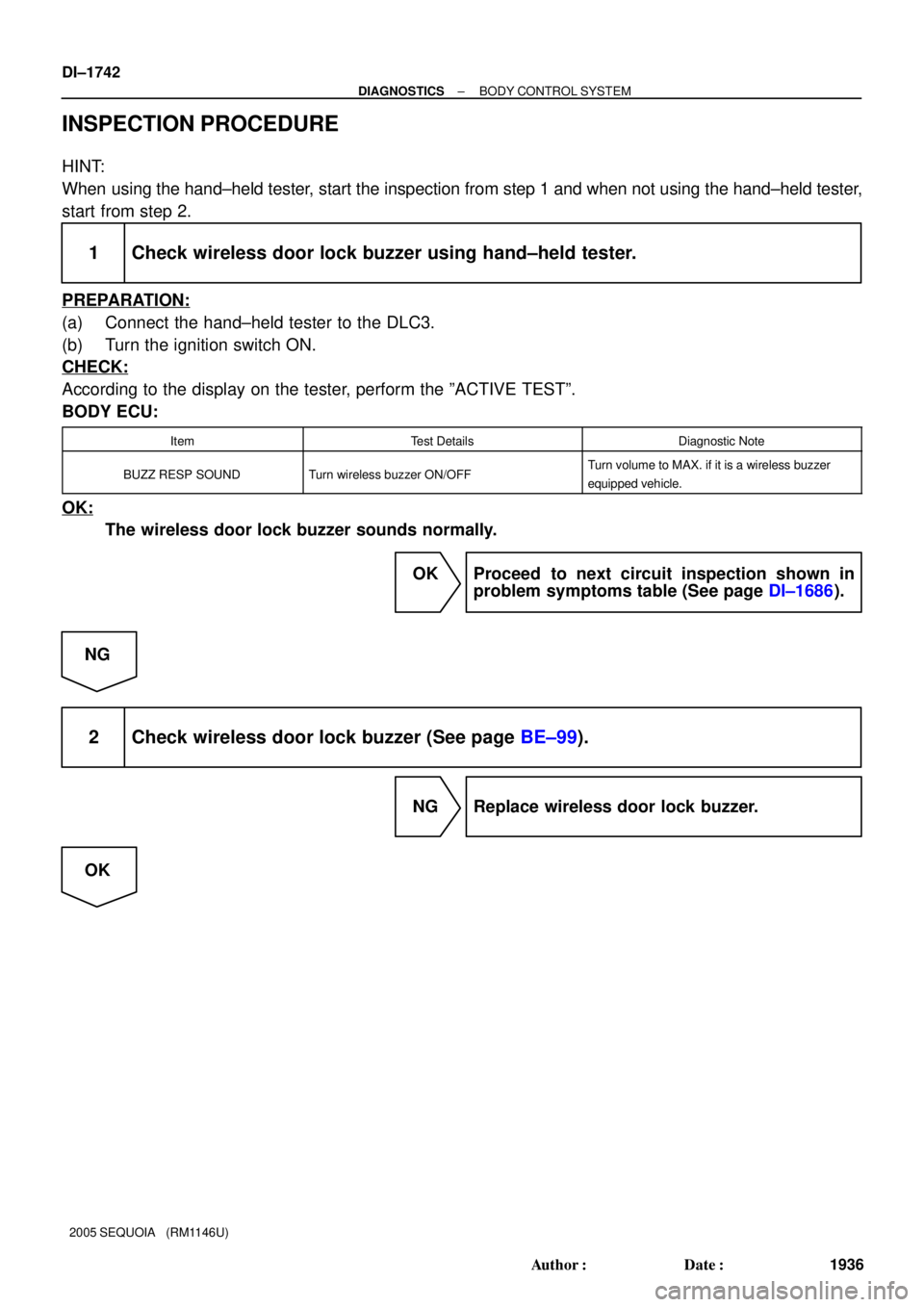
INSPECTION PROCEDURE
HINT:
When using the hand±held tester, start the inspection from step 1 and when not using the hand±held tester,
start from step 2.
1 Check wireless door lock buzzer using hand±held tester.
PREPARATION:
(a) Connect the hand±held tester to the DLC3.
(b) Turn the ignition switch ON.
CHECK:
According to the display on the tester, perform the ºACTIVE TESTº.
BODY ECU:
ItemTest DetailsDiagnostic Note
BUZZ RESP SOUNDTurn wireless buzzer ON/OFFTurn volume to MAX. if it is a wireless buzzer
equipped vehicle.
OK:
The wireless door lock buzzer sounds normally.
OK Proceed to next circuit inspection shown in
problem symptoms table (See page DI±1686).
NG
2 Check wireless door lock buzzer (See page BE±99).
NG Replace wireless door lock buzzer.
OK
Page 2108 of 4323
B1242
(DI±1933)
Wireless door lock tuner circuit malfunction
�Wireless door lock control receiver
�W")
DI±1906
± DIAGNOSTICSMULTIPLEX COMMUNICATION SYSTEM
2100 Author�: Date�:
2005 SEQUOIA (RM1146U)B1242
(DI±1933)
Wireless door lock tuner circuit malfunction
�Wireless door lock control receiver
�Wire harness
�Body ECU
B1243
(DI±1935)GSW terminal circuit malfunction
�Airbag sensor assembly
�Wire harness
�Body ECU
B1244
(DI±1937)Light sensor circuit malfunction
�Automatic light control sensor
�Wire harness
�Body ECU
B1262
(DI±1940)A/C ECU communication stop
�A/C ECU (Integration control and panel)
�Wire harness
�Body ECU
B1271
(DI±1943)Combination meter ECU communication stop
�Combination meter
�Wire harness
�Body ECU
B1272
(DI±1946)Memory seat ECU communication stop
(w/ Driving position memory)�Memory seat ECU & switch
�Wire harness
�Body ECU
B1273
(DI±1949)Sliding roof ECU communication stop
(w/ Sliding roof)�Sliding roof ECU
�Wire harness
�Body ECU
B1287
(DI±1952)Back door ECU communication stop
�Back door ECU
�Wire harness
�Body ECU
HINT:
�When either DTC B1214 or B1215 is output, a DTC for another ECU communication stop may also
be output. In this case, perform troubleshooting for DTC B1214 or B1215 first. DTC B1214 or B1215
is output when a short to +B or short to ground occurs on a communication bus.
�DTCs from B1221 to B1241 do not indicate that the corresponding switch is abnormal. They notify how
the switch is operating.
If the corresponding DTC is not indicated when operating a switch, there is a problem with the switch
contact.
If a DTC is indicated when not operating switches, the corresponding switch is stuck.
Page 2116 of 4323
DI±1914
± DIAGNOSTICSMULTIPLEX COMMUNICATION SYSTEM
2108 Author�: Date�:
2005 SEQUOIA (RM1146U)
DTC B1214 Communication bus malfunction
(Short to B+)
DTC B1215 Communication bus malfunction
(Short to ground)
CIRCUIT DESCRIPTION
DTC B1214 or B1215 is detected when a short to +B or short to ground occurs on the multiplex communica-
tion bus (BEAN). Detecting this condition will disable the multiplex communication bus (BEAN) and output
the corresponding DTC.
DTC NO.DTC detecting conditionTrouble area
B1214Short to B+ in multiplex communication system communica-
tion circuit
�Driver door ECU
�Passenger door ECU
�Back door ECU
�A/C ECU (Integration control panel)
�Combination meter
�Memory seat ECU & switch
�Wire harness
�Body ECU
B1215Short to ground in multiplex communication system commu-
nication circuit
�Driver door ECU
�Passenger door ECU
�Back door ECU
�A/C ECU (Integration control panel)
�Combination meter
�Memory seat ECU & switch
�Wire harness
�Body ECU
DI94Y±07
Page 2166 of 4323

FM (Monaural)
AM
BE2819
Ionosp")
DID9P±01
30 kHz 300 kHz 3 MHz 30 MHz 300 MHz
LF MF HF VHF
AM FM
Frequency modulation Frequency
Designation
Radio wave
Modulation Amplitude modulation
BE2818
FM (Stereo)
FM (Monaural)
AM
BE2819
Ionosphere Phasing DI±1964
± DIAGNOSTICSAUDIO SYSTEM
2158 Author�: Date�:
2005 SEQUOIA (RM1146U)
IDENTIFICATION OF NOISE SOURCE
1. RADIO WAVE BAND
The radio wave bands used in radio broadcasting are as follows:
LF: Low Frequency
MF: Medium Frequency
HF: High Frequency
VHF: Very High Frequency
2. SERVICE AREA
There is a great difference in the size of the service areas for
AM and FM broadcasting. Sometimes an FM stereo broadcast
cannot be received even though AM can be received very clear-
ly.
FM stereo has the smaller service area, it also picks up static
and other types of interference (ºnoiseº) easily.
3. RECEPTION PROBLEMS
HINT:
Besides the problem of static, there are other problems, such as ºphasingº, ºmultipathº and ºfade outº. These
problems are caused not by electrical noise but by the nature of the radio waves themselves.
(a) Phasing
Besides electrical interference, AM broadcasts are also
susceptible to other types of interference, especially at
night. This is because AM radio waves bounce off the ion-
osphere at night. These radio waves then interfere with
the signals that reach the vehicle's antenna directly from
the same transmitter. This type of interference is called
ºphasingº.