Page 2493 of 4323
I28480
Combination Meter
SPD G±O 25
C53
R29 J17
J/C
BRadio and Navigation Assy
BG±O
± DIAGNOSTICSNAVIGATION SYSTEM
DI±2291
2485 Author�: Date�:
2005 SEQUOIA (RM1146U)
Speed signal circuit
CIRCUIT DESCRIPTION
The navigation ECU (built in the radio and navigation assy) receives a vehicle speed signal from the com-
bination meter assy and information about the GPS antenna, and then adjusts vehicle position.
HINT:
�A voltage of 12 V or 5 V is output from each ECU and then input to the combination meter. The signal
is changed to a pulse signal at the transistor in the combination meter. Each ECU controls the respec-
tive system based on the pulse signal.
�If a short occurs in an ECU, all systems in the speed signal circuit will not operate normally.
WIRING DIAGRAM
DIDDP±01
Page 2504 of 4323

DI3EZ±06
Inspector 's name:
Customer 's Name
VIN
Production Date
Licence Plate No.
Odometer Readingkm
miles Date vehicle
Brought In / /
Date of Problem Occurrence
How Often does Problem Occur?
Weather
Outdoor Temperature / /
� Continuous � Intermittent ( times a day)
� Fine � Cloudy � Snowy � Various /Other
� Hot � Warm � Cool � Cold (Approx.°F
°C)
Symptoms� Blower motor does not operate
� Blower motor speed does not change
(Always Hi, Always Med, Always Lo)
Air Flow Control is
Faulty
� Cabin temperature does not go down
� Response is slow
� Cannot change between FRS and REC
(Always Fresh or always Recirculating)
� Will not enter the desired mode Temperature
Control is Faulty
Air Inlet Control is
Faulty
Vent Control is
Faulty
DTC Check1st Time
2nd Time� Normal Code � Malfunction Code (Code )
� Normal Code � Malfunction Code (Code )
AIR CONDITIONING SYSTEM Check Sheet
� Cabin temperature does not rise
� Mode will not change DI±2302
± DIAGNOSTICSAIR CONDITIONING SYSTEM
2496 Author�: Date�:
2005 SEQUOIA (RM1146U)
CUSTOMER PROBLEM ANALYSIS CHECK
Page 2506 of 4323

DI3F3±10
DI±2304
± DIAGNOSTICSAIR CONDITIONING SYSTEM
2498 Author�: Date�:
2005 SEQUOIA (RM1146U)
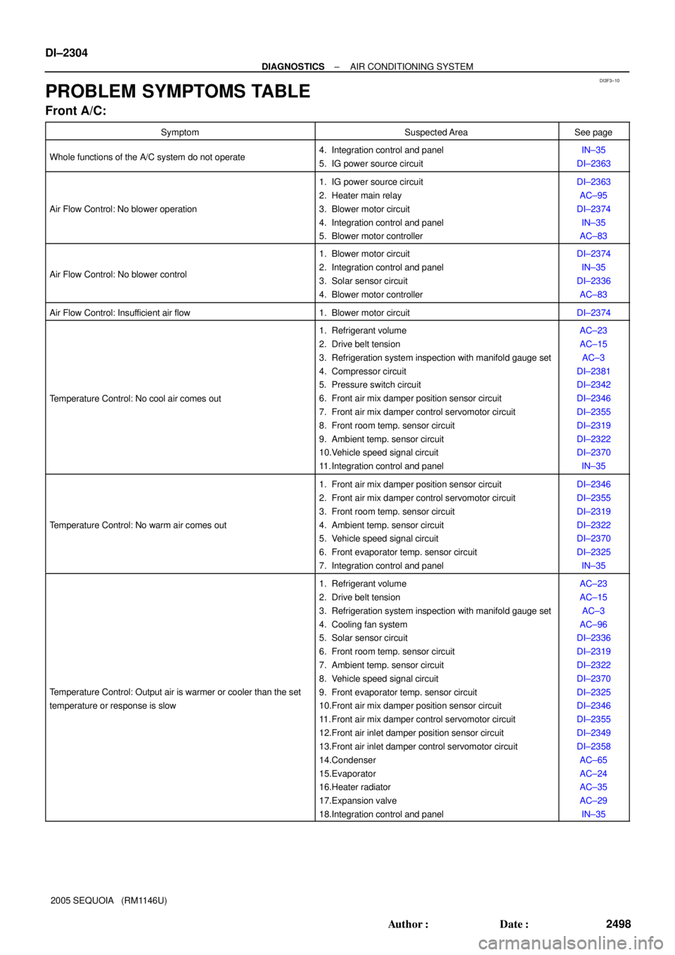
PROBLEM SYMPTOMS TABLE
Front A/C:
SymptomSuspected AreaSee page
Whole functions of the A/C system do not operate4. Integration control and panel
5. IG power source circuitIN±35
DI±2363
Air Flow Control: No blower operation
1. IG power source circuit
2. Heater main relay
3. Blower motor circuit
4. Integration control and panel
5. Blower motor controllerDI±2363
AC±95
DI±2374
IN±35
AC±83
Air Flow Control: No blower control
1. Blower motor circuit
2. Integration control and panel
3. Solar sensor circuit
4. Blower motor controllerDI±2374
IN±35
DI±2336
AC±83
Air Flow Control: Insufficient air flow1. Blower motor circuitDI±2374
Temperature Control: No cool air comes out
1. Refrigerant volume
2. Drive belt tension
3. Refrigeration system inspection with manifold gauge set
4. Compressor circuit
5. Pressure switch circuit
6. Front air mix damper position sensor circuit
7. Front air mix damper control servomotor circuit
8. Front room temp. sensor circuit
9. Ambient temp. sensor circuit
10.Vehicle speed signal circuit
11. Integration control and panelAC±23
AC±15
AC±3
DI±2381
DI±2342
DI±2346
DI±2355
DI±2319
DI±2322
DI±2370
IN±35
Temperature Control: No warm air comes out
1. Front air mix damper position sensor circuit
2. Front air mix damper control servomotor circuit
3. Front room temp. sensor circuit
4. Ambient temp. sensor circuit
5. Vehicle speed signal circuit
6. Front evaporator temp. sensor circuit
7. Integration control and panelDI±2346
DI±2355
DI±2319
DI±2322
DI±2370
DI±2325
IN±35
Temperature Control: Output air is warmer or cooler than the set
temperature or response is slow
1. Refrigerant volume
2. Drive belt tension
3. Refrigeration system inspection with manifold gauge set
4. Cooling fan system
5. Solar sensor circuit
6. Front room temp. sensor circuit
7. Ambient temp. sensor circuit
8. Vehicle speed signal circuit
9. Front evaporator temp. sensor circuit
10.Front air mix damper position sensor circuit
11. Front air mix damper control servomotor circuit
12.Front air inlet damper position sensor circuit
13.Front air inlet damper control servomotor circuit
14.Condenser
15.Evaporator
16.Heater radiator
17.Expansion valve
18.Integration control and panelAC±23
AC±15
AC±3
AC±96
DI±2336
DI±2319
DI±2322
DI±2370
DI±2325
DI±2346
DI±2355
DI±2349
DI±2358
AC±65
AC±24
AC±35
AC±29
IN±35
Page 2508 of 4323

DI±2306
± DIAGNOSTICSAIR CONDITIONING SYSTEM
2500 Author�: Date�:
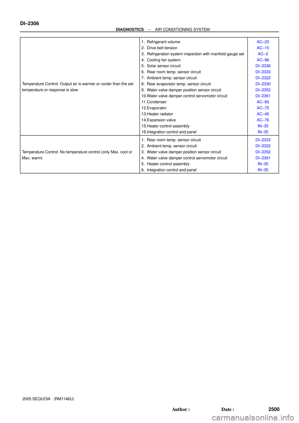
2005 SEQUOIA (RM1146U) Temperature Control: Output air is warmer or cooler than the set
temperature or response is slow
1. Refrigerant volume
2. Drive belt tension
3. Refrigeration system inspection with manifold gauge set
4. Cooling fan system
5. Solar sensor circuit
6. Rear room temp. sensor circuit
7. Ambient temp. sensor circuit
8. Rear evaporator temp. sensor circuit
9. Water valve damper position sensor circuit
10.Water valve damper control servomotor circuit
11. Condenser
12.Evaporator
13.Heater radiator
14.Expansion valve
15.Heater control assembly
16.Integration control and panelAC±23
AC±15
AC±3
AC±96
DI±2336
DI±2333
DI±2322
DI±2330
DI±2352
DI±2361
AC±65
AC±70
AC±45
AC±76
IN±35
IN±35
Temperature Control: No temperature control (only Max. cool or
Max. warm)
1. Rear room temp. sensor circuit
2. Ambient temp. sensor circuit
3. Water valve damper position sensor circuit
4. Water valve damper control servomotor circuit
5. Heater control assembly
6. Integration control and panelDI±2333
DI±2322
DI±2352
DI±2361
IN±35
IN±35
Page 2743 of 4323

SF1XD±01
± SFISFI SYSTEM
SF±1
2735 Author�: Date�:
2005 SEQUOIA (RM1146U)
SFI SYSTEM
PRECAUTION
HINT:
All DTCs retained in the ECM will be erased when the negative
(±) terminal cable is removed from the battery.
If necessary, read the DTC before removing the negative (±)
terminal cable from the battery.
1. BEFORE WORKING ON FUEL SYSTEM,
DISCON-
NECT CABLE FROM NEGATIVE (±) BATTERY TERMI-
NAL
2. DO NOT SMOKE OR WORK NEAR AN OPEN FLAME
WHEN WORKING ON FUEL SYSTEM
3. KEEP GASOLINE AWAY FROM RUBBER OR
LEATH-
ER PARTS
4. MAINTENANCE PRECAUTIONS
(a) To prevent engine misfire, these precautions should be
taken.
(1) Check the battery terminals are proper connected.
(2) After repair, check that the ignition coil terminals
and all other ignition system lines are reconnected
securely.
(3) When cleaning the engine compartment, be espe-
cially careful to protect the electrical system from
water.
(b) Observe the following when handling the air fuel ratio
sensors and oxygen sensor.
(1) Do not drop the sensor or hit it against another ob-
ject.
(2) The sensor should be free from any contact with wa-
ter.
5. IF VEHICLE IS EQUIPPED WITH MOBILE RA-
DIO
SYSTEM (HAM, CB, ETC.)
If the vehicle is equipped with a mobile communication system,
refer to the precaution in the IN section.
6. AIR INDUCTION SYSTEM
(a) Removal of the engine oil dipstick, oil filler cap, PCV hose,
may break the engine.
(b) Disconnection, looseness or cracks in the parts of the air
induction system between the throttle body and cylinder
head may result in air suction and break the engine.
7. ELECTRONIC CONTROL SYSTEM
(a) Before removing SFI wiring connectors, terminals, first
disconnect the power by turning the ignition switch off or
disconnecting the negative (±) terminal cable from the
battery.
HINT:
Be sure to check DTCs before disconnecting the negative (±)
terminal cable from the battery.
Page 2744 of 4323

FI2553
SST
B16498
New Gasket
SF±2
± SFISFI SYSTEM
2736 Author�: Date�:
2005 SEQUOIA (RM1146U)
(b) When installing the battery, be especially careful to cor-
rectly connect the positive (+) and negative (±) cables.
(c) Do not give a severe impact to the SFI parts during remov-
al or installation. Handle all SFI parts carefully, especially
the ECM.
(d) Be careful during troubleshooting. Numerous transistor
circuits are used and even slight terminal contact can
cause further trouble.
(e) Do not open the ECM cover.
(f) When inspecting during rainy weather, take care to pre-
vent entry of water. Also, when washing the engine
compartment, prevent water from getting into the SFI
parts and wiring connectors.
(g) Parts should be replaced as an assembly.
(h) Care should be taken when pulling out and inserting wir-
ing connectors.
(1) Release the lock and pull out the connector, pulling
on the connectors.
(2) Fully insert the connector and check that it is locked.
(i) Use SST for inspection or test of the injector or its wiring
connector.
SST 09842±30070
8. FUEL SYSTEM
(a) When disconnecting the high fuel pressure line, a large
amount of gasoline will spill out. Observe the following
procedures:
(1) Disconnect the circuit opening relay.
(2) Start the engine. After the engine has stopped on
its own, turn the ignition switch off.
(3) Put a container under the connecting part of the
pressure line.
(4) Slowly loosen the connection.
(5) Disconnect the high fuel pressure line.
(6) Reconnect the fuel pump connector.
(b) When connecting the union bolt (fuel pressure pulsation
damper) on the high pressure pipe union, observe the fol-
lowing procedures:
(1) Always use 2 new gaskets.
(2) Tighten the union bolt by hand.
Page 2993 of 4323
PR01G±06
F19802�Non±reusable part
N´m (kgf´cm, ft´lbf) : Specified torqueSpider BearingSnap Ring �
�
Spider �
Sleeve Yoke
Spider � Propeller Shaft
Spider Bearing
Snap Ring � �Flange Yoke
88 (897, 65)
.
PR±2
± PROPELLER SHAFTPROPELLER SHAFT ASSEMBLY (2WD)
2985 Author�: Date�:
2005 SEQUOIA (RM1146U)
PROPELLER SHAFT ASSEMBLY (2WD)
COMPONENTS
Page 3126 of 4323

F14520SST
SA2347
SST
SA2446
R04453
SA±122
± SUSPENSION AND AXLEREAR DIFFERENTIAL CARRIER
3118 Author�: Date�:
2005 SEQUOIA (RM1146U)
(3) Adjust the drive pinion preload by tightening the
companion flange nut.
HINT:
Using SST to hold the flange, torque the nut.
SST 09330±00021
NOTICE:
As there is no spacer, tighten the nut a little at a time and
be careful not to overtighten it.
(4) Remove the 3 nuts and SST.
(e) 4WD:
Adjust the drive pinion preload by tightening the compan-
ion flange nut.
HINT:
Using SST to hold the flange, torque the nut.
SST 09330±00021
NOTICE:
As there is no spacer, tighten the nut a little at a time and
be careful not to overtighten it.
(f) Using a torque wrench, measure the preload of the drive
pinion using the backlash between the drive pinion and
ring gear.
Preload (at starting):
New bearing
1.3 ± 1.9 N´m (13 ± 19 kgf´cm, 11.4 ± 16.7 in.´lbf)
Reused bearing
0.8 ± 1.1 N´m (8 ± 11kgf´cm, 7.0 ± 9.7 in.´lbf)
(g) 2WD:
Remove the stud bolts from the companion flange.
8. INSTALL DIFFERENTIAL CASE IN CARRIER
(a) Place the 2 bearing outer races on their respective bear-
ings. Make sure the right and left races are not inter-
changed.
(b) Install the differential case in the carrier.
9. ADJUST RING GEAR BACKLASH
(a) Install the plate washer on the ring gear back side.
HINT:
Make sure that the ring gear has backlash.