Page 1955 of 4323
I03114
A27
Automatic Light
Control Sensor
CLTS Y
R±G
BRCLTB
CLTEBody ECU
12
B6 4
1
34
B6
3
B6 CLTS
CLTB
CLTE
± DIAGNOSTICSBODY CONTROL SYSTEM
DI±1753
1947 Author�: Date�:
2005 SEQUOIA (RM1146U)
Automatic light control sensor circuit
CIRCUIT DESCRIPTION
The body ECU detects the ambient light level outside the vehicle via the automatic light control sensor.
The body ECU turns the headlights ON and OFF based on the ambient light level sensed by the automatic
light control sensor.
WIRING DIAGRAM
DI1OL±28
Page 1957 of 4323

I28521
1B
1B1
2
7
1B 1F9Y±R
B6
B6 11
8
R±L Instrument Panel J/B
Y±R
W±BHF HU
J8
J/C A
IE16 LOW
HIGH
FLASH Headlight
Dimmer
Switch
W±BC8 Combination Switch
EL HF HU87Body ECU w/ Daytime Running Light:
± DIAGNOSTICSBODY CONTROL SYSTEM
DI±1755
1949 Author�: Date�:
2005 SEQUOIA (RM1146U)
Headlight dimmer switch circuit
CIRCUIT DESCRIPTION
This circuit detects the headlight dimmer switch condition.
w/ daytime running light:
The body ECU detects the headlight dimmer switch position and turns on the DIMMER relay.
The body ECU informs the combination meter of the headlight dimmer switch condition via BEAN.
When the headlight dimmer switch position is HI or FLASH, the HI beam indicator light on the combination
meter comes on.
w/o daytime running light:
When the headlight dimmer switch position is HI or FLASH, the HI beam indicator light on the combination
meter comes on.
When the HI beam headlights come on, current is supplied to the HI beam indicator light on the combination
meter to turn the indicator light on.
WIRING DIAGRAM
DI94U±08
Page 1964 of 4323
DI±1762
± DIAGNOSTICSBODY CONTROL SYSTEM
1956 Author�: Date�:
2005 SEQUOIA (RM1146U)
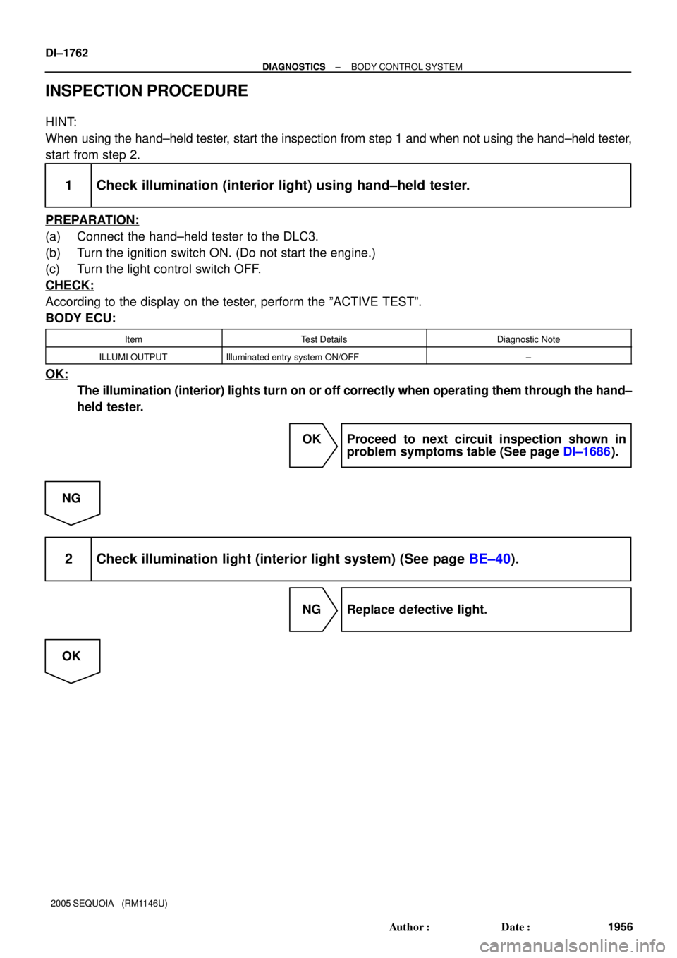
INSPECTION PROCEDURE
HINT:
When using the hand±held tester, start the inspection from step 1 and when not using the hand±held tester,
start from step 2.
1 Check illumination (interior light) using hand±held tester.
PREPARATION:
(a) Connect the hand±held tester to the DLC3.
(b) Turn the ignition switch ON. (Do not start the engine.)
(c) Turn the light control switch OFF.
CHECK:
According to the display on the tester, perform the ºACTIVE TESTº.
BODY ECU:
ItemTest DetailsDiagnostic Note
ILLUMI OUTPUTIlluminated entry system ON/OFF±
OK:
The illumination (interior) lights turn on or off correctly when operating them through the hand±
held tester.
OK Proceed to next circuit inspection shown in
problem symptoms table (See page DI±1686).
NG
2 Check illumination light (interior light system) (See page BE±40).
NG Replace defective light.
OK
Page 2582 of 4323
I07763
1
2
4
I07764
3
4
DI±2380
± DIAGNOSTICSAIR CONDITIONING SYSTEM
2574 Author�: Date�:
2005 SEQUOIA (RM1146U)
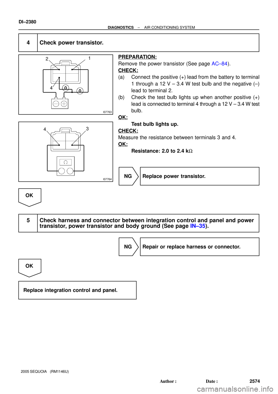
4 Check power transistor.
PREPARATION:
Remove the power transistor (See page AC±84).
CHECK:
(a) Connect the positive (+) lead from the battery to terminal
1 through a 12 V ± 3.4 W test bulb and the negative (±)
lead to terminal 2.
(b) Check the test bulb lights up when another positive (+)
lead is connected to terminal 4 through a 12 V ± 3.4 W test
bulb.
OK:
Test bulb lights up.
CHECK:
Measure the resistance between terminals 3 and 4.
OK:
Resistance: 2.0 to 2.4 kW
NG Replace power transistor.
OK
5 Check harness and connector between integration control and panel and power
transistor, power transistor and body ground (See page IN±35).
NG Repair or replace harness or connector.
OK
Replace integration control and panel.
Page 2904 of 4323
CH±4
± CHARGINGCHARGING SYSTEM
2896 Author�: Date�:
2005 SEQUOIA (RM1146U)
If the voltmeter reading is more than the standard voltage, re-
place the voltage regulator.
If the voltmeter reading is less than the standard voltage, check
the voltage regulator and generator.
10. INSPECT CHARGING CIRCUIT WITH LOAD
(a) With the engine running at 2,000 rpm, turn on the high
beam headlights and set the heater blower switch to HI.
(b) Check the reading on the ammeter.
Standard amperage: 30 A or more
If the ammeter reading is less than the standard amperage, re-
pair the generator.
HINT:
If the battery is fully charged, the indication will sometimes be
less than standard amperage.
11. REINSTALL ENGINE UNDER COVER
Page 2986 of 4323

(f) Push the 2WD/4HI switch once")
F19319
2WD/4HI Switch
F19320
4LO Switch
F19321
Differential Lock Switch
TR±40
± TRANSFERONE TOUCH 2±4 SELECTOR SYSTEM
2978 Author�: Date�:
2005 SEQUOIA (RM1146U)
(f) Push the 2WD/4HI switch once again.
(g) Check that the 4WD and center differential lock indicator
lights go off after blinking.
4. INSPECT 2WD e 4LO (4WD and differential lock
ºFREEº)
(a) Start the engine.
(b) Push the 4LO switch once.
(c) Check that the 4LO indicator light stays lit after blinking.
(The 4WD and center differential lock indicator lights blink
while shifting.)
(d) Push the 2WD/4HI switch once.
Check that the 4LO indicator light goes off after blinking.
(The 4WD and center differential lock indicator lights blink
while shifting.)
5. INSPECT 4LO (4WD and differential lock ºFREEº) e
4LO (4WD and differential lock ºLOCKº)
(a) Start the engine.
(b) Push the 4LO switch once.
(c) Check that the 4LO indicator light stays lit after blinking.
(d) Push the differential lock switch once.
(e) Check that the center differential lock indicator light stays
lit after blinking.
(f) Push the differential lock switch once again.
(g) Check that the center differential lock indicator light goes
off after blinking.
Page 2988 of 4323

8. INSPECT 4LO (4WD and differential lock ºLOCKº) \"
2W")
F19324
2WD/4HI Switch
F19325
A GND
4LO
CPU 4WD
B TR±42
± TRANSFERONE TOUCH 2±4 SELECTOR SYSTEM
2980 Author�: Date�:
2005 SEQUOIA (RM1146U)
8. INSPECT 4LO (4WD and differential lock ºLOCKº) "
2WD
(a) Start the engine.
(b) Push the 4LO switch once.
(c) Check that the 4LO indicator light stays lit after blinking.
(d) Push the differential lock switch once.
(e) Check that the center differential lock indicator light stays
lit after blinking.
(f) Push the 2WD/4HI switch once.
(g) Check that the 4LO and center differential lock indicator
lights go off after the 4LO and 4WD indicators are blink-
ing.
9. INSPECT 2WD/4HI, 4LO AND DIFFERENTIAL LOCK
SWITCH CONTINUITY
(a) Remove the instrument panel finish lower panel.
(b) Inspect the continuity between each terminal.
Switch positionTester connectionSpecified condition
Diff. Lock OFFB±8 ± A±10No continuity
Diff. Lock Hold ONB±8 ± A±10Continuity
4LO OFFB±9 ± A±10No continuity
4LO Hold ONB±9 ± A±10Continuity
2WD/4HI OFFB±10 ± A±10No continuity
2WD/4HI Hold ONB±10 ± A±10Continuity
If continuity is not as specified, replace the instrument panel fin-
ish lower panel.
Page 3181 of 4323

BRAKE PEDAL
ON±VEHICLE INSPECTION
1. CHECK PEDAL HEIGHT
Pedal hei")
F07754
Pedal Height Push Rod
BR107±04
R00085
Pedal Free Play BR±6
± BRAKEBRAKE PEDAL
3173 Author�: Date�:
2005 SEQUOIA (RM1146U)
BRAKE PEDAL
ON±VEHICLE INSPECTION
1. CHECK PEDAL HEIGHT
Pedal height from dash panel:
151.1 ± 165.1 mm (5.949 ± 6.500 in.)
NOTICE:
Do not adjust the pedal height. Doing so by changing the
push rod length of the brake booster will structurally
change the pedal ratio.
If the pedal height is incorrect, check that there is no damage
in brake pedal, brake pedal lever, brake pedal bracket and dash
panel.
�Even if there is damage, there is no problem if the
reserve distance is within the standard value.
�If necessary, replace them.
2. IF NECESSARY, ADJUST STOP LIGHT SWITCH
(a) Remove the front door scuff plate, cowl side trim, side
panel, lower finish panel and No. 2 heater to register duct
(See page BO±89).
(b) Loosen the stop light switch lock nut.
(c) Push the brake pedal in 5 ± 15 mm (0.20 ± 0.59 in.), turn
the stop light switch to lock the nut in the position where
the stop light goes off.
(d) Push the brake pedal in 5 ±15 mm (0.20 ± 0.59 in.), check
that the stop light lights up.
(e) Install the No. 2 heater to register duct, lower finish panel,
side panel, cowl side trim and front door scuff plate (See
page BO±89).
3. CHECK PEDAL FREE PLAY
(a) Stop the engine and depress the brake pedal several
times until there is no more vacuum left in the booster.
(b) Push in the pedal by hand until the second point of resis-
tance begins to be felt, then measure the distance as
shown in the illustration.
Pedal free play: 1 ± 6 mm (0.04 ± 0.24 in.)
HINT:
The free play to the first point of resistance is due to the play
between the clevis and pin. It is 1 ± 3 mm (0.04 ± 0.12 in.) at the
pedal.
If incorrect, check the stop light switch clearance. If the clear-
ance is OK, then troubleshoot the brake system.
Stop light switch clearance:
0.5 ± 2.4 mm (0.020 ± 0.095 in.)